Note: Descriptions are shown in the official language in which they were submitted.
2035457
The present invention relates to a bed suitable for use by a physically-
handicapped person or an aged person having problems with bodily functions.
Beds are now available for use by a person having problems with bodily
functions, in which a part thereof supporting the upper half of a human body is
S pivotally so as to be moved upward and downward, whereby the upper half of the
human body can be raised from a condition where the person is lying down on his or
her back to a condition that the person is sitting up whereby such person may eat a
meal or read a book.
Beds which are used for me~ l treatment and thus have a completely
different purpose from the present invention, are known for the medical treatment of
the spinal cord, as disclosed in Japanese Patent Publication No. 1977/27472 and
Japanese Patent No. 86424. The bed for medical treatment disclosed in the above-
described Japanese Patent Publication No. 1977/27472 is designed to treat an unusual
spinal cord in such a manner as to change the posture of a human body by pivoting
somewhat rightward and leftward, moving somewhat forward and backward, or
twisting the foot part of the bed somewhat. Also, the bed for medical treatment
described in Japanese Patent No. 86424 is similarly designed to pivot rightward and
leftward the feet part of the bed.
According, such beds used for spinal cord tr~tm.ont move in such a manner
20 that the upper half of the body part of the bed is fixed, while the foot part, that is,
the lower half of the body part is moved to cure a deformation of the spinal cord.
In prior art beds, however, it has been very difficult for a physically-
handicapped person or an aged person having problems with bodily functions to turn
the body direction 90 degrees by ones self and then assume a posture such that the
2 2035457
feet drop down to the floor when the person comes down from a bed to the floor, is
held by a male nurse, or is carried on his or her back.
A purpose of the present invention is to provide a bed capable of easily
çh~nging the posture of a physically-h~n~ic~Med person or an aged person having
5 problems with bodily functions from a posture of lying on the back of the body to a
posture convenient to come down on the floor or to be held by a nurse.
By one aspect of the present invention, a bed is provided which is divided into
a front bed section for receiving the upper half of the body at least above the femur
and a rear bed section for receiving the lower half of the body under the waist; the
shape of the divided part between the both bed sections when viewed from above
being in the form of a circular arc traced with the centre of the forward bed section;
and a pivoting meçh~ni~m between a fixed frame and a pivoting frame supporting the
both bed sections in a manner to pivot and stop the front bed section from a condition
where the front bed section is moved forward and backward with respect to the fixed
rear bed section to a condition where the front bed section is moved in the direction
either right or left.
By another aspect of the present invention, a bed is provided which is divided
into a front bed section for receiving the upper half of the body at least above the
femur and a rear bed section for receiving the lower half of the body under the waist,
and in which a ~uppo~ g frame of the front bed section is divided into a waist
~uppol~illg frame and a back suppo-li,lg frame, the free end of the waist suppulLing
frame being pivotally provided to be moved upward so that femur supporting part of
the front bed section can be swung to a higher position; a pivoting mech~ni~m
between a fixed frame and a pivoting frame in such a manner as to pivot and stop the
,~.
3 2035~57
front bed section from a condition where the front bed section is moved forward and
backward with respect to the fixed rear bed section to a condition where the front bed
section is moved in the direction either right or left; and an actuating mechanism for
moving the free end of the waist supporting frame upward so as to move at least the
S femur ~up~ol~ing part of the front bed section upward when the pivoting frame is
pivoted by the driving force of the pivoting mech~ni.cm.
By yet another aspect of the present invention, a bed is provided which is
divided into a front bed section for receiving the upper half of the body at least above
the femur and a rear bed section for receiving the lower half of the body under the
waist, and in which the suppol~ g frame of the front bed section is divided into a
waist ~upl)ol~ing frame and a back supporting frame, the top of the back supporting
frame being pivotally provided to be moved upward so that the back receiving part
of the front bed section can be bent; a pivoting mechanism between a fixed frame and
a pivoting frame in such a manner as to pivot and stop the front bed section from a
condition where the front bed section is moved forward and backward with respectto the fixed rear bed section to a condition where the front bed section is moved in
the direction either right or left; and a bending mechanism to stand the back
supporting frame-up when the pivot frame is pivoted by the driving force of the
pivoting me~.h~ni~m.
By a still further aspect of the present invention, a bed is provided which is
divided into a front bed section for receiving the upper half of the body at least above
the femur and a rear bed section for receiving the lower half of the body under the
waist, and in which the suppolling frame receiving the front bed section is pivoted
when viewed from above is adapted to move sideward and stop the front bed section;
2~3~4~7
and a collision preventive mechanism for upward and downward separating the front
bed section from the rear bed section when the front bed section is pivoted so as to
prevent the end faces of the both bed sections from colliding with each other.
By yet a further aspect of the present invention, a bed handrail is provided foruse in combination with the right and left sides of a bed which is divided into a front
bed section for receiving the upper half of the body at least above the femur and a
rear bed section for receiving the lower half of the body under the waist, for allowing
the front bed section to be pivotable when viewed from above with respect to the rear
bed section, and whose rear part can be set toward the inside of the bed.
In other words, the present invention is arranged in such a manner that a bed
is divided into a front bed section for receiving the upper half of the body at least
above the femur and a rear bed section for receiving the lower half of the body under
the leg. The shape of the divided part between the both bed sections when viewedfrom above is in the form of a circular arc traced with the centre of the front bed
lS section. A pivoting mech~ni~m is provided between a fixed frame and a pivoting
frame in such a manner as to pivot a convex circular arc part of the front bed section
with respect to the fixed rear bed section from a condition that the section is moved
forward and backward to a condition that the section is moved in the direction of
either rightward or leftward and stopped.
The arrangement allows the posture of a human body to be easily changed
such that, when a physically-handicapped person or an aged person gets off a bed,
held by a male nurse, or is carried on his or her back, the pivoting mech~ni~m is
driven to pivot the front bed section 90 degrees with respect to the rear bed section,
thereby easily ch~nging to a posture convenient for the feet of the patient to slide on
.~
2 ~ 3 ~ ~ 5 ~
the surface of the fixed rear bed section and come down from the bed, or to a posture
convenient to be held by a male nurse or carried on his or her back.
Also, in the present invention, a bed is divided into a front bed section for
receiving the upper half of the body at least above the femur and a rear bed section
for receiving the lower half of the body under the leg, a supporting frame of the front
bed section is divided into a waist suppo, Ling frame and a back supporting frame, and
the free end of the waist supporting frame is pivotally provided to be moved upward
so that a femur suppolLillg part on the waist supporting side of the front bed section
can be swung to a higher position. A pivoting mechanism is provided between a
fixed frame and a pivoting frame in such a manner as to pivot the front bed section
from a condition that the section is moved forward and backward with respect to the
fixed rear bed section to a condition that the section is moved in the direction of
either rightward or leftward and stopped. An ~ct ~ing mechanism is provided for~ upward moving the free end of the waist supporting frame so as to move at least the
femur supporting part of the front bed section upward when the pivoting frame ispivoted. by the drive force of the pivoting mechanism.
The arrangement allows a smooth pivoting to be pelro"~ed such that, when
the fee of the patient slide on the surface of the fixed rear bed section during pivoting
of the front bed section, by raising the femur supporting part of the front bed section,
the section can be pivoted without difficulty in a condition that only the top of the feet
slide on the surface of the fixed rear bed section in a knee upward bending posture.
In this case, if a bending mech~ni~m for standing up the back supporting frame
is provided, the pivoting becomes more effective because acondition is obtained
.~',~,
5a 2035 157
where a person using the bed raises the upper half of the body thereof when the
pivoting frarne is pivoted by the drive force of the pivoting mech~ni~m
Also, in the present invention, divided right and left end parts of the both bedsections are provided in straight line when viewed from above, and a collision
preventive mel h~ni~m is provided for s~al~ing upward and downward the front bedsection from the rear bed section when the front bed section is pivoted so as toprevent the end faces of the both bed sections from colliding with each other,
whereby the divided parts need not to be made a special shape of circular arc. Also,
a sheet covered on the bed can be easily turned down and stretched under the bed so
that no extra wrinkles develops on the sheet.
Further, handrails for a bed according to an aspect of the present invention aresuch that the rear parts of the handrails can be set toward the inside of the bed, so
that a user, when he or she comes down on the floor, can easily go down and stand
while gripping the displaced handrails near his both sides.
In the accompanying drawings,
Fig. 1 is a side view of the whole of a bed;
Fig. 2 is a plan view of the whole of a bed;
Fig. 3 is a side view of a pivoting frame;
Fig. 4 is a side view of Fig. 3;
Fig. 5 is a plan view of Fig. 3;
Fig. 6 is a side view of a principal part of an actuating mech~ni~m for
~t~-~ting the pivoting frame;
5b 2~35457
Fig. 7 is a plan view of the principal part;
Fig. 8 is a principal part showing a condition of the mounting of a back
supporting frame;
5~
~'
20~4~7
Fig. 10 is a side view showing a pivoting mechanism of the
handrail;
Fig. 11 is a front view of a principal part showing the
pivoting of the handrail;
Figs . 1 2, 13, 14 and 1 5 are plan views showing drawings of
the pivoting process of the pivoting mechanism for the pivoting
frame;
Figs. 16 , 17 , 18 , 19 and 20 are side views of a pricipal part
showing the operation and the process of the bending actuation of
a front bed section;
Fig. 21 is a side view showing the whole posture changed
condition;
Fig. 22 is a side view showing a posture when a person on the
bed is taking a meal or a condition at a time when pivoting is
started;
Fig. 23 is a side view showing a condition that the pivoting
frame has completed pivoting thereof and then a person goes down
and stands on the floor, or a condition that a person is held by
a male nurse or carried on his back;
Fig. 24 is a side view of another embodiment;
Fig. 25 is a plan view of the embodiment;
Fig. 26 is a side view showing a condition of a changed
posture of the embodiment;
Fig. 27 is a side view showing a condition at a time when the
pivoting of the embodiment is started;
2~3~5~
Fig. 28 is a side view showing a condition at a time when the
pivoting has completed;
Fig. 29 is a partially cutaway side view of a futher
embodiment;
Fig. 30 is a side view showing the midway point of an
actuation of the embodiment;
Fig. 31 is a plan view of the embodiment;
Fig. 32 is a side view of a still futher embodiment; and
Fig. 33 is an electric control circuit diagram.
BEST FORM TO PERFORM THE INVNEION
Based on the drawings showning embodiments according to the
present invention, an explanation will be given hereinafter. In
the drawings, a fixed frame 1 of a bed is supported by front feet
2 and rear feet 3, the middle part the frame in the forward-
backward direction is concaved downward when viewed from side, and
a right side frame 1a and a left side frame 1b are properly
connected by joining frames 1c when viewed from above. Signs 4
and 5 indicate a front board and a rear board, respectively.
A pivoting frame 6 of the bed is fixed to a pivoting plate 8
which is pivotally provided by being supported upward and downward
with bearings in a clearance between a lower fixed ring 7a fixed
to the joining frame 1c located on the concave being the middle
part of the fixed frame 1 and a upper fixed ring 7b integrally
fixed to the lower fixed ring 7a. The pivoting frame 6 also
comprises side frames 6a and 6b stretching in the forward-backward
203~57
direction on the right and left side, a tie frame 6c, a tie frame
6c for connecting to the pivoting plate 8, a mounting frame 6d
for connecting the tie frame 6c, and the like.
The pivoting mechanism of the pivoting frame 6 will be
explined hereinafter. First, fixed cams 9a and 9b are fixedly
secured on the fixed ring 7b with the cams extending on the right
and left side on the upper surface of the ring and is provided
with cam grooves A and B displaced toward the center in the
backward-to-forward direction.
On the other hand, the pivoting frame 6 is provided with a
transmission mounting frame 16 which is integrally fixed to the
frame 6 and formed in a rectangular shape when viewed from above;
on the frame 16 a motor 10 is mounted in such a manner that the
direction of a drive output shaft lOa is in the forward-backward
direction; a screw shaft 12 is in the forward-backward direction
connected through a friction transmission joint 11 serving also as
a shock release to the shaft lOa; and the screw shaft 12 is
pivotally beared by the transmission mounting frame 16. A screw
cylinder 13 is threadly engaged with the screw shaft 12; shafts 14
and 15 as a mechanism for stopping the rotation of the screw
cylinder 13 are provided on the right and left side of the
cylinder; and to the shafts, rollers 17 are mounted which abute
and are rollingly moved on the right and left frames 16a and 16b
of the frame 16.
A lateral frame 18 has holes 18a and 18b on the right and
2~3!~
left side for inserting or disinserting cam pins 19; and the pins
are arranged such that, when the pin 19 is inserted into the
right hole 18a or the left hole 18b of the lateral frame 18 and
the motor 10 is rotated to move forward the screw cylinder 13, the
lower end of the pin 19 is fitted into the cam groov A of the cam
9a or the cam groove B of the cam 9b in a manner to pivot in a
body with the motor 10 through the transmission mounting fram 16
the pivoting frame 6 rightward or leftward. Also, the pins are
arranged such that, when the motor 10 is reversely rotated to
move backward the screw cylinder 13, the cam action at the time
when the pin 19 is slided out from the cam groove A or B causes
the pivoting frame 6 to be pivoted reversely to the above motion
and to be reset. Although the pivoting angle of the pivoting
frame 6 varies with the displaced angle and length of the cam
grooves A and B, in the present invention, when the pivoting frame
pivotes substantially 90 degrees, the friction transmission joint
11 acts to stop the frame.
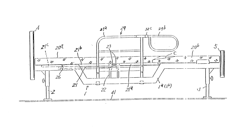
The front bed supporting frame 21 for supporting the front
bed section 20a for receiving the upper half of the body above the
femur on the pivoting frame 6 is provided with brackets 24 and 25
for fixing with pins 23 the waist supporting frame 21a and the
back supporting frame 21b, respectively, to projection frames 22
projected in reverse U-shape from the pivot frame 6; the bases of
the supporting frames 21a and 21b are pivotally secured; and the
pivoting tops thereof are properly supported by the pivoting frame
- lo -
~3~4~
6 in a manner to become substantilly horizontal. Also, the top
of the back supporting frame 21 b is provided with a head
supporting frame 21c pivotally secured with a pin 26 on the frame
21c; and the head supporting frame 21c is arranged such that the
frame 21c is connected through links 27 to the projection frames
22 to keep only the head supporting frame 21c in a horizontal
posture when the back supporting frame 21b is pivoted upward.
When the base of a rod 27a of the link 27 is connected to a
bracket 28 fixedly secured on the back supporting frame 21b, the
head supporting frame 21c is pivoted in a body with the back
supporting frame 21b without pivoting horizontally, whereby
posture change-over means for changing the mounting of the rod
27a is arranged.
Cylinders 30 for inserting and disinserting the handrail 29
are provided on the four corners of the pivoting frame 6. The
handrail 29 comprises a gate-shape fixed handrail 29a which is
inserted into the cylinders 30 and fixed thereto and a pivoting
handrail 29b which is pivotally inserted in the forward-backward
direction into bosses 29c formed integrally with the rear upper
end of the handrail 29a and which is then mounted with a screw 31
and a slip-out preventive groove 32a cutted on an insertion shaft
32. 'rhe pivoting handrail 29b is formed in substantially
elliptical loop with a pipe, and arranged such that the position
of the handrail 29b is chanded over to a position at which the
handrail hangs down or to a position at which the handrail is
2a~4~
stopped diagonally somewhat downward by means of pivoting stopper
29d and 32b provided on the boss 29c and the pivoting handrail 29b
at -the end face of the insertion shaft 32, respectively. Sign
32c indicates a cover of the stoppers.
The front bed section 20a being a mat for normal bendable bed
is placed on the upper surface of the front bed supporting frame
21 provided as described above on the pivoting frame 6, and the
rear end of the front bed section 20a is formed in circular arc
traced with the pivoting center of the pivoting frame 6 as a
center.
The rear bed section 20b is placed on the upper suface on the
rear side of the fixed frame 1, the front end face is formed in
circular arc traced with the pivoting center of the pivoting
frame 6 as a center, and projections C and D on the right and left
sides of the bed 20b having a concave shape when viewd form above
are inclined in such amanner that the more close to the both
edges they reach, the thinner they become than other part.
The pivoting mechanisim of the waist supporting frame 21a and
the back supporting frame 21b pivotally mounted through the
projection frames 22 on the pivoting frame 6 will be explained
hereinafter. On the underside of the supporting frames 21a and
21 b, cam rollers 35 and 36 through brackets 33 and 34 are
rollingly provided through laterally mounted shafts. Also, a cam
37 abuting on the cam roller 35 is fixedly secured on the right
side of the lateral frame being in a body with the screw cylinder
-~2-
2 a ~ ~ ~ ~ 7
13, and a cam 38 abutting on the ca~ roller 36 is fixedly secured
on the left side of the screw cylinder 13; and when the screw
shaft 12 is rotated ~y the motor 10 to move forward the screw
cylinder 13, the ca~ roller 36 is pushed by the front end
vertical face of the cal~ 3a to cause the baclc supporting fralne
21h to be gradually pivoted bac]cward, and substantially at the
same time the ca~ roller 35 is ~radually pushed up by the cam
37 to cause the rear side of the ~aist supporting frame 21a
to be pivoted somewhat up~ard. Then, some~hat prior to the
condition as shown in Fig. 18, the cam pin 19 having been
inserted into the hole 18a or 18b on the one side of the lateral
frame 18 is fitted into the cam groove A or B of the fixed cam
9a or 9b located on the pin 19 side, and thereafter when the
scre~,7 cylin~er 13 moves forward and the pin 19 approaches the
bias of the car1 groove, the pivoting fralne 6 begins to pivot
rigl1t~ar(l or leftward. Then, ~7hen the frame 6 pivots
substantially 45 degre2s, the bac}c supporting frame 21b lo~7ers
in a manner to beco~e gentle in inclination and at the salne
time the waist supporting frame 21a hecomes gradually sharp
in inclination wl~ the pivoting fralne 6 further pivots. There-
after, when the pivoting frame 6 asslllnes a final pivoting posture
in whicll the frame pivots substantially 90 degrees, the bac~c
supporting frame 21b ~ide becolnes in vertical condition and
the waist supporting fr~me 21b returns to horizontal condition.
In such manner as described above, the relative position of
each ca~ to pin or cam roller, and the sha~e of tile cam has
been set.
-13-
203~7
A switch hox 39 is provide~ in such a manner that a person
having trouble in the hody thereof or an a~ed person on the
~ed, or a m~le nurse can freely operate throu~ll the switch
~o~ with a cord from any position thc motor 10, and arranged
such that the motor can be freely rotated naturally or reversely
b~ change-over o~ the switch, whereby the rotation direction
of the screw shaft 12 is chan(3ed to cause the screw cylinder
13 to be moved forward or backward.
Sign 40 in(licates a slide member which is made of leather
or synthetic rubber and provided on the one end face or both
end Laces ~etween the convex circular arc end face of the upper
half of the body supportin~ bed section 20a and the concave
circular arc end face of the lower half of the body supporting
bed section 20b to smooth the pivoting of the both end faces.
~ he operation of the above example will be e~plained in
detail hereinafter.
A person havin~ trou~le in the body thereof or an aged
person is laid on hack thereof on thc bed witll the upper half
of the body above the waist supported by the front bed section
20a and with thc leg supported by the rear bed section 20b.
When such person wants to change the posture thereof from a
posture in which the person is lying to a posture in which the
person raises the upper half of the l~ody thereof to tal~e a ri~eal,
to a posture in which the person cOMes down on the right side
( left side witll resp~ct to the laid person ) floor 41, or to
a posture in which the person is held by a male nurse or carried
on his back, tlle cam pin 19 has previously been inserted into
-1 4-
203~457
the left sicle hole 18a or the lateral fraIlle 1~3 as shown in Figs.
7 and 3, ancl then ti-te screw shaft 12 is allowed to rotate
rigI1tward by the motor 10 to rnove forward the screw cylinder
13. '~Ilen, the cam roller 35 mountec-l through the bracket 33 on
the waist supporting frarle 21a is first pushed up by the cam
37, and at the sai1e tiMe the cam roller 36 mounted through tJle
E)racI~et 3~1 on the }~ack su~?porting frame 21b abutes on the front
face of tilC' cam 313 to pivot the supporting frames 21a and 21b
as shown in the operation processes of Figs. 16 thou~h 18,
w}lerehy a postur2 in which the upper half of the body is raisecd
to talce a meal or read a }~ooIc as shown in Fig. 21 and 22 is
attained. I~owever, if only the posture is clesired, the cam pin
19 needs not to have been insertecl into the hole 18.
'l'hen, w}len the motor 10 is further rotated from such
condition to move forward the screw cylinder 13, the cam pin
19 abutes on the l)ias part in the cam groove A of the right
fixecl cam 9a provided on the bed fixecl frame 1 to pivot the
frame 16 providecl with the motor 10 and the pivoting frame 6
l)eing in a body with the frame 16 right~-7ard ( in the arrow E
direction) with respect to the fixed frame 1 as shown in the
conditions of Fig. 13 through Fig. 14. Fig. 15. At the time
when the condition of Fig. 1~ in the course of pivoting is
attainecl, the relative ~osition of the cam rollers 35 and 36
to the caI,ls 37 ancl 3~ is in the condition of Fig. 18, and when
the screw cylinder 13 is further moved forward, the pivoting
frame 6 an(l the drive inclu(1ing the motor 10 are pivoted
suJ~stantially 45 degrees from the condition of Fig. 14 to that
-15-
2035~57
of Fit3. 15, that is, about 90 degrees from the first condition.
At the time when the final pivoting of about 45 degrees is
L~erformed, the relative position of the cam rollers 35 and 36
to the callls 37 and 38 is changed from the condition of Fig.
1~ to that of Fig. 20, that is, the baclc supporting frame 21h
once pivots somewhat bacl;ward and at the same time the waist
supporting frame 21a becomes somewhat higher, and thereafter
the bac]c supporting frame 21b again stands and at the same
ti,-,me the waist supporting frame 21a becomes hori20ntal.
lnat is, the laid person assumes finally thro~lgh the condition
or Fig. '2 the posturc of ~ig. 23.
In order to return the posture of Fig. 23 to the original
posture in which the bed is in the forward-bac~ward direction,
the motor 10 is allowe(1 to rotate rightward (reverse to the
above-described rotation ), whereby an operation completely
reverse to the above-described operation can be performed to
return to the original lying posture. Further, in order to
pivot reversely the pivoting frame 6 to reverse the come-down
side, the cam pin 19 must be inserted into the other hole 1~b
to be fitted into the cam groove B of the right fixed cam 9b.
On the other hand, in the processes of the front bea section
20a operation as shown in Fig. 22 to 23, the waist supporting
fra,ne 21a and the hac~c supporting frame 21b are operated in
the conditions shown in Fig. 1~ through 20 as described above,
so that a person on the bed swings somewllat upward the femur
near the waist thereof supported by the top of the waist
supporting frame 21a to prevent the free thereof from pivoting
-16-
203~457
~hile beillg ~Iholly rubbed on the fixed rear bed section 20b,and
to prevcnt the root opposite to the pivoting direction from
being caught by the fi~ed rear bed section 20b to cause foot
t~7istin~. ~t this time, s~inging only the waist supporting
frame 21a causes the person on the hed to be excessively bent
an.l have a pain, so that, to prevent such condition, an operation
is perforined such that the bac~ supporting frame 21b is fell
some~lllat bac]~rard, and thereafter stands up again at the same
time ~7hen the ~7aist supporting frame 21a returns to horizontal
condition.
.~ccordingly, a lying person can finally be in the posture
of lig. 23 to be faced toward the si(le of the bed. 11hen the
person s~ants to come do~m on the floor 41 in that posture, by
allo~Jing the hanclrail 29h to pivot to the virtual line in Fig.11
an-l to he in a posture of Fig. 23 in ~hich the handrail is
pivoted, the person can come down on the floor 41 while grasping
the handrail 29b ~ithout (lifficulty.
IJhere in order to prevent a pillow 42 or a book placed
near tne pillo~l from falling ~Jhen the front bed section 20a
is pivoted and bent, the base of the rod 27a of the linls
mechanism 27 is allo~7ed to have been connectecl to the braclcet
22a of the projection 22, when the bac] supporting frame 21b
is pivoted up~ard, the head supporting frame 21c is lept at
all times horizontal as sho~m ~ith the virtual line in Fig.
~, so that the head side bed section is hardly changed as in
the posture of Fig. 21 or 22, thereby preventing the pillo~7
42 or another o~ject placed near the pillo~ from slipping off.
-17-
- 2035~57
Fig. 25 and dra~ings that follow show an embodiment
different from the above-described embodiment. In that invention,
the front hed section 20a and the rear bed section 20b are formed
in rectangular shape when viewed from above, this is, the divided
part is not formecl in circular arc as in the above-described
embodiment. Upper parts Ii and I of the right and left corners
on the front side of the rear bed section 20b are inclined in
a manner to be gradually lowered with respect to other part.
The other part is substantailly similar to the above-described
embodiment, and the same sign is assigned to the same part.
~1}1cn thc scrc~1 shaft 12 is rotated by the motor 10 to move
for~ard the scrc~-7 cylinder 13 for the pivoting of the waist
.~u-i~porting frarne 21a and the back supporting frame 21b, the
cam roller 36 is pushed by the front end vertical face of the
cam 3~ to pivot ~radually bacl~ward the back supporting frame
21b in a manner not to strike a~ainst the board 4 during
pivoting, and substantially at the same time, the cam roller
35 is gradually pushed up by the cam 37 to pivot upward the
rear part of the waist supporting frame 21a in a manner not
to strike against the rear bed section 20b during pivoting.
That is, the collision preventive mechanism S being one
embodiment according to the present invention is composed of
the cam roller 35 mounted through the bracket 33 to the waist
supporting frame 21a and of the cam 37.
A femur guide 43 is arranged such that mat rnembers thereof
are l-nounted on the right and left wall faces of the fixed frame
1 correspon(ling to the divided line het~een the front bed section
-1~3-
2035~5~
20a and the rear i)ed section 20b, and is designed to guide
slnootl1ly the feraur to prevent from being injured or nightclothes
from being caugl1t wllen the front bed section 20a is pivoted
to cause the feet of a lying person to he hung down on the
floor, or on the contrary when the front bed section 20a is
reversaly pivoted with a person sitting on a chair to cause
the person to be laid on the bed.
Besicles th2 above-aescribed embodiment, the collision
prevtntive mechanisn S may be arranged in such a manner as shown
in the third embodim2nt of Fig. 29 where the pivoting frame
6 is provide~ ,1ovably upward and downward through a front lin]~
--lGa and a rear lin]~ ~5b on the fixed frame 1, and the front
lin~ a is connectecl to a screw cylinder 49 thread engaged
~7ith a scre~ shaft 48 wl1ich is naturally or reversely rotated
by a motor 47 for up~Jard and down-Jard rnovement mounted on the
fi~ed fra,i1e 1 side, so that the pivoting frame 6 is moved upward
by the natural and reverse rotation of the motor 47 as shown
in Fig. 30 to rnalce the front l~ed section 20a higher than the
rear hed section 20b, thereby preventing the collision during
L~ivotin~. In this case, the operation Mechanism composed of
the roller 35 for diagonally moving the waist supporting frame
21a, the car,1 37 and the li~e- in the above-described embodiment
is omitted. In case of the third eMbodiment, the natural and
reverse rotation and the stoppa~e of the motor 47 are controlled
by a controller 50 in a rnanner to be perforn1ed relating to the
pivoting of the front bed section 20a.
That is, when a s~litch 39a of a manual switch box 39 is set
--1 9--
~ 203~57
to Oi~, first the .,motor 47 is naturally rotated to move upward
the front becl section 20a to cause the section to become a
condition as shown in Fi~. 30, then the motor 10 be~ins to he
rot~ted to move sideward and stop the front bed section 20a,
and thereafter the motor 47 is reversely rotated to move downward
and stop the front bed section 20a. On the contrary, in order
to allo~J a sitting person to lie on the bed, an operation reverse
to the above-(lescribed operation is perforrned such that, when
a switch 39b is set to O-~l, the motor 47 is reversely rotated
to n1ove up~Jarcl ancl stop the front bed section 20a, then the
motor 10 is reversely rotated to return tlle front bed section
20a to the original position in the forward-bac~ward direction
and stc~i~ the section, and thereafter the Inotor 47 is reversely
rotated to move the section to the original position as sho~m
in rii~J. 29 and stop the section.
~ 3esides tlle L~revious second and third embodiments, in an
e,~bodil1ent as shown in Fig. 32, the collision preventive
mechanis~ is arran~ed such that the rear bed section 20b is
supported by a rear bed supporting frame 51 which is Inovable
up~Jard and do~m~Jard through links 52a and 52b, and the lin]
52a is connected to a scre~J cylinder 55 threadly engaged with
a scre~J shaft 54 ~Jhich is naturally and reversely rotatable
by a motor 53 mounted on the fixed frame 1, whereby the rear
bed section 20b is allowed to lower from the position shown
with the virtual line to the position shown with the solid line
in Fi~. 32 to prevent the rear bed section 20b from colliclin~
with the front bed section 20a when pivoted. In this case, it
- ~o -
2G3~7
is also preferable that the motor 4~ is automatically controllecl
hy the controller as shown in the third embodiment.
I~owever, in case of that fourth embodiment, when the switch
39a of the manual switch box 39 is set to OI~J, first the r,lotor
4~ is reversely rotated to move downward the rear bed section
20b, then the motor 10 begins to be rotated to move sideward
and stop the front bed section 20a, and thereafter the motor
~}~ is naturally rotated to move upward and stop the rear bed
section 207D. On the contrary, in order to allow a sitting person
to lie on the becl, the controller is arran~ed such that, when
the switch 39b is set to ON, as reverse to the above-described
operation, th2 motor 53 is naturally rotated to move down~Jard
and stop the rear bed section 20b, then the motor 10 is reversely
rotated to return the front bed section 20a to the original
pOsitioIl in the forward-baclcward direction and stop the section,
and therearter the motor 53 is naturally rotated to move the
section to the original position and stop the section. The fourth
eIabodiiilent is arranged such that the rear bed section 20b is
moved down~ard to prevent a collision with the front bed section
20a when pivoted, so that it is not particularly necessary that
the motor 10 begins to be rotated to move sideward the front
hed section 20a and then the motor 53 is naturally rotated to
ove up~Jard the rear be(l section 20b, and thus that condition
is left as it is; and then when a sitting person is allowed
to lie on the bed, the controller may be arranged such that
the motor 10 is reversely rotated as it is to pivot the front
bed section 20a to the original position thereof, and then the
2 ~
motor 53 is naturally rotated to move upuard the rear bed section
20b.
T}le upper-surface inclinecl parts II and I at the front side
corners of tlle rear bed section 20b have such a function that,
even ~here a sheet of thick bedquilt 56 is placed on the front
and rear bed sections and the front becl section 20a is moved
sidcward to~Jether with the thiclc bedquilt as it is to cause
the rcar part of the thick bedqllilt 56 placed on the rear bed
section 20b to he hun~ down, when the front bed section ~Oa
is pivoted and reset, the inclined parts automatically push
up the hun~-(lo~Jn thick bedquilt 56 onto the rear hed section
20b to effect the automatic rear of the front bed section 20a.
Il~JDusTr~IArJ AVAILAi3ILITY OF UTILIZATIOr~J
As described above, the bed according to the present
invention can be utilized as a bed used for a physically
hallclica-t~pe(l person or an aged person having trouble in the body
thereof.