Note: Descriptions are shown in the official language in which they were submitted.
fJ~ J~
FIELD OF THE INVENTION
This invention relates to a fluid dispenser for
dispensing a predetermined volume of fluid from a large container
of fluid. More particularly, the present invention relates to a
dispenser for dispensing fluids, such as liquid soap from a
flexible, collapsible bag.
.
BACKG~OU~ID OF THE IMVENTION
Fluid dispensers are well known for use within
institutional environments that require the sanitary and hygienic
dispensation of substances such as soaps and shampoos. One known
type of fluid dispenser is wall-mountable, and utilizes an
internal bag or tube that is filled with fluid, such as liquid
soap. The bag is flexible and disposable. Further, the bag has
two chambers, namely, a main upper reservoir compartment and a
lowee dispensing bulb that is capable of holding a measured
amount of fluid. A dispensing spout extends downwardly from the
bulb, and hangs externally from the dispenser.
~ , .
various fluid dispensers have been proposed for use with
such bags, utilizing both gravitational and mechanical forces.
Such dispensers~ however, typically have two major problems,
namely the ability to effectively seal the opening between the
main reservoir and the dispensing bulb, and the requirement of a
relatively complex mechanical device to expel the fluid from the
bag.
' ` .` '
. ' .
s~ ' r~
-- -- 2
An attempt has been made to remedy these problems.
United states patent no. 4,463,876 relates to a fluid dispensing
device in which upper and lower pinching mechanisms are provided
for pinchiny the discharge portion of the bag, below the main
reservoir. The upper pinching mechanism includes a fixed jaw and
a movable jaw, while the lower pinching mechanism includes two
jaws which are each movable with respect to the stationary
housing and with respect to one another. As a result, it is
necessary to provide stops on the stationary housing which serves
to limit the movement of one of the lower jaws while permitting
continued movement of the other jaw. ThiS arrangement therefore
requires a complex mechanism which does not ensure a tight or
effective seal between the movable lower jaws.
:~ .
SUMMARY OF THE INV~NTION
An object of the present invention is to provide a fluid
dispenser for use with a disposable, compressible bag having
means to effectively expel fluids of varying viscosities.
' ' ' .
A further object Oe the present invention is to provide
a fluid dispenser with means for discharging fluid from the bag
that is relatively simple in construction and which can
effectively seal the discharge portion of the bag.
According to one broad aspect of the present invention~
there is provided a fluid dispenser of the type which is used to
dispense a fluid such as soap from a container, of the type
having a flexible discharge tube through which fluid may be
3 ~ J ~
discharged along a fluid dispensing path that extends through a
dispenser station. The dispenser has an upper and lower tube
pinching means each having a fixed jaw and a movable jaw located
opposite one another and arranged one on a first side and one on
a second side of the fluid dispensing path. The movable jaws are
mounted for movement along a second path which intersects said
fluid dispensing path so as to be movable toward their associated
fixed jaw to a closed position in which they cooperate therewith
to pinch the discharge tube and thereby prevent the discharge of
fluid from the discharge tube and for movement away from their
associated fixed jaw to an open position in which they permit the
discharge tube to open to allow the discharge of fluid
therefrom. The upper and lower movable jaws are arranged one on
said first side of said discharge path and one on said second
side of the said discharge path and are interconnected by
actuator means which is mounted in said dispenser station for
movement to and fro along said second path from a first position,
in which the upper jaw is in its open position and the lower jaw
is in its closed position, to a second position, in which the
upper jaw is in its closed position and the lower jaw is in its
open position~ Further, tube compression means are carried by
said actuator means and are located in a first position in which
it will not compress said tube when the actuator means are
located in its first position and serves to compress said tube,
and it is carried by actuator means into compressive contact with
said tube, to expel fluid therefrom as the actuator means moves
from its first position to its second position, said tube
compression means being carried by said actuator means out of
,:! t~
compressive contact with said tube to permit said fluid to enter
said tube as said actuator means moves from its second position
to its ~irst position.
BRIEF DESCRIPTION OF DRAWINGS
_
With reference to the accompanying drawings, by way of
example and not limitation, an example embodiment of the
invention is shown in which:
Fig. 1 is a side view, in partial section, showing the
fluid dispenser of the present invention;
Fig. 2 is a side view, in partial section, showing the
fluid dispenser of Fig. 1 in operation;
Fig. 3 is a perspective view, in partial section, of the
pumping mechanism oE the fluid dispenser; and,
Fig. 4 is a perspective view of the fluid dispenser of
Fig. 1.
.... , ~ . .
f; ~ "~
-- 5
- - ,
DESCRIPTION OF PREFERRED EMBODIMENTS
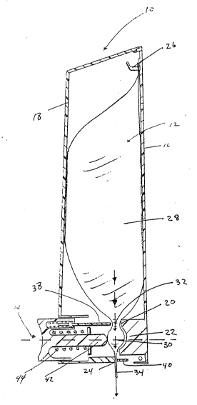
With reference to the drawings, the device of the
present invention generally comprises a frame 10, a flexible
discharge bag or tube 12 that is mounted within said frame 10 and
extends downwardly therefrom, and a dispensing station or
mechanism 14 that is resiliently mounted within said frame 10.
Frame 10 comprises a backplate 16 which is adapted to be
mounted to a wall, a cover 18 is pivotally connected to the top
of said backplate 16, and a bottom base (not shown~. An upper
fixed jaw 20 is mounted to said backplate 16. A concave-shaped
anvil 22 is integrally connected to said upper fixed jaw 20. A
lower fixed jaw 24 is mounted to said bottom base, and is
positioned forwardly of said upper fixed jaw 20. A mounting hook
26 is located towards the top of backplate 16.
Flexible discharge tube 12 comprises a main, upper
reservoir 28 and a lower bulb 30 that is generally spherical in
shape. A tubular passage 32 connects reservoir 28 to bulb 30,
and spout 34 extends downwardly from said bulb. Discharge tube
12 is adapted to be mounted within frame 10 by attachment at its
upper end to mounting hook 26.
When flexible discharge tube 12 is mounted within frame
10, dispensing bulb 30 is aligned horizontally with, and
forwardly of, concave-shaped anvil 22 while tubular passage 32 is
aligned horizontally with, and forwardly of, upper fixed jaw 20.
Spout 34 is aligned horizontally with, and rearwardly of, lower
fixed jaw 24.
-,.. ~. ...
- 6 ~
Dispensing station 14 includes a push button actuator
means 36 that extends externally from said frame 10. Integrally
mounted to said actuator means, and located internally of said
frame, are an upper movable jaw 38 and a lower movable iaw 40.
Lower ~ovable jaw 40 is positioned rearwardly of said upper
movable jaw 38. Positioned between said movable jaws 38 and 40,
and also mounted to said actuator means is a movable hammer 42
having a convex-shaped face. A spring 44 is positioned around
said hammer, thereby resiliently mounting said dispensing station
14 within the frame.
When mounted for use, spring 44 urges the integrally
mounted upper movable jaw 38, lower movable jaw 40 and hammer 42
to their static positions. In this first position, spout 3~ is
pinched between fixed lower jaw 24 and the retracted movable
lower jaw 40, as these lower pinching mechanisms are in their
closed positions. ~luid is there~by prevented from being
discharged from bulb 30, as spout 34 is pinched by these lower
pinching mechanisms. Fluid from the main reservoir 28 is
permitted to flow downwardly through tubular passage 32 and into
dispensing bulb 30, however, as the upper movable jaw 38 is in
its open position, retracted away from compressive contact with
said tubular passage 34.
~ hen it is desired to expel or discharge fluid from tube
17, the user exerts peessure upon actuator means 36. This
pressure causes the integrally mounted upper movable jaw 38,
lower movable jaw 40 and hammer 42 to move inwardly, in unison.
~j? ~!~` 7
As a result, tubular passage 32 is pinched between movable upper
jaw 38 and fixed upper jaw 20 and movable upper jaw 38 which is
in its closed position. This creates an effective seal between
reservoir 28 and dispensing bulb 30, so that fluid is prevented
from flowing downwardly into the discharge path. In this second
position, hammer 42 is moved into compressive contact with
dispensing bulb 30, as the hammer 42 is urged towards anvil 22,
while lower movable jaw 40 moves apart from lower fixed jaw 24.
As a result, spout 34 is opened to permit fluid to be expelled
from dispensing bulb 30, and through spout 34.
'
Once the fluid from the dispensing bulb 30 has been
discharged, the user releases pressure from the push button
actuator means 36. The spring mounted actuator means thereby
return the upper movable jaw 38, lower movable jaw 40 and hammer
42 to their original static positions, thus closing the lower
pinching mechanisms while opening the upper pinching mechanisms.
It will be appreciated that by providing an upper pair
of movable and fixed jaws and a lower pair of movable and fixed
jaws, each of which act upon opposed sides of said disposable
tube 12, a simple mechanical mechanism can be employed for
effectively dispensing fluid from the tube and for sealing the
discharge tube from any undesired leakage.