Language selection

Search

Patent 2035795 Summary

Third-party information liability

Some of the information on this Web page has been provided by external sources. The Government of Canada is not responsible for the accuracy, reliability or currency of the information supplied by external sources. Users wishing to rely upon this information should consult directly with the source of the information. Content provided by external sources is not subject to official languages, privacy and accessibility requirements.

Claims and Abstract availability

Any discrepancies in the text and image of the Claims and Abstract are due to differing posting times. Text of the Claims and Abstract are posted:

  • At the time the application is open to public inspection;
  • At the time of issue of the patent (grant).
(12) Patent: (11) CA 2035795
(54) English Title: RIVETING APPARATUS
(54) French Title: APPAREIL A RIVETER
Status: Expired and beyond the Period of Reversal
Bibliographic Data
(51) International Patent Classification (IPC):
  • B21J 15/12 (2006.01)
  • B21J 15/04 (2006.01)
  • B21J 15/20 (2006.01)
  • B25B 27/00 (2006.01)
(72) Inventors :
  • SCHWAB, MANFRED (Germany)
(73) Owners :
  • MASCHINENBAU SUBOTSCH VERWALTUNGS- UND BETEILIGUNGS-GMBH
(71) Applicants :
  • MASCHINENBAU SUBOTSCH VERWALTUNGS- UND BETEILIGUNGS-GMBH (Germany)
(74) Agent: KIRBY EADES GALE BAKER
(74) Associate agent:
(45) Issued: 1997-12-30
(22) Filed Date: 1991-02-06
(41) Open to Public Inspection: 1991-08-11
Examination requested: 1994-10-20
Availability of licence: N/A
Dedicated to the Public: N/A
(25) Language of filing: English

Patent Cooperation Treaty (PCT): No

(30) Application Priority Data:
Application No. Country/Territory Date
G 90 01 315.8 (Germany) 1990-02-06

Abstracts

English Abstract


In a hydraulically or manually operated riveting
apparatus having two pivotal levers for performing the actual
riveting operation and a screwthreaded mandrel which can be
caused to rotate the screwing on the rivet nut and for
screwing out after the rivet setting operation it is provided
at the rear end of the apparatus housing which is in opposite
relationship to the screwthreaded mandrel a turning means in
the form of a rotary head which is non-rotatably connected to
a draw spindle connected to the screwthreaded mandrel which
projects at the front end of the apparatus.


French Abstract

La présente invention vise une machine à riveter hydraulique ou manuelle comportant deux leviers pivotants servant aux opérations de rivetage proprement dites, et un mandrin fileté qu'on peut faire tourner pour poser un rivet. € l'autre extrémité du boîtier de l'appareil, opposée au mandrin, se trouve un dispositif d'actionnement de ce dernier, ayant la forme d'une tête rotative solidaire d'une tige de manoeuvre.

Claims

Note: Claims are shown in the official language in which they were submitted.

Claims:
1. A riveting apparatus, hydraulically operated or as a
hand-riveting apparatus comprising:
a housing;
two pivotal levers connected to said housing and
operationally connected to the apparatus for performing the
actual riveting operation;
a screwthreaded mandrel projecting at a front end of said
housing and which can be caused to rotate for screwing on the
rivet and for screwing out the rivet after the rivet setting
operation, a draw spindle connected to a rear end of said
screw threaded mandrel and extending through a rear end of
said housing, and a turning means in the form of a rotary head
arranged on the apparatus housing outside the plane of the
handle tubes and connected by way of a gear transmission means
to the draw spindle.
2. Apparatus according to claim 1 characterized in that the
rotary shaft of the rotary head extends in a plane
perpendicularly to the draw spindle and carries a bevel gear
meshing with a bevel gear carried on the draw spindle.
3. Apparatus according to claim 1 wherein said rotary head
is of a cylinder form.
4. Apparatus according to claim 1 characterized in that the
rotary head is mounted on a sleeve carried rotatably on the
rear end of the apparatus housing.
5. Apparatus according to claim 4 characterized in that the
sleeve can be fixed in different positions.
6. Apparatus according to claim 5 characterized in that the
sleeve carries a fixing pin which engages into openings
provided on the apparatus housing.

7. Apparatus according to claim 6 characterized in that the
sleeve is steplessly adjustable in respect of its rotational
position by a friction fit on the apparatus housing.

Description

Note: Descriptions are shown in the official language in which they were submitted.


Jo3579~
Riveting APparatus
The invention relates to a riveting apparatus having two
pivotal levers for performing the actual riveting operation
and a screwthreaded mandrel which can be caused to rotate for
screwing on the rivet nut and for screwing out after the rivet
setting operation.
A riveting operation can admittedly be carried out
without difficulties, with apparatuses of that kind, but it
requires a large number of handling operations which represent
stress for the operator, which in the course of prolonged
operating periods results in fatigue, while in addition the
performance of the individual handling operations requires a
great amount of time. Thus, firstly the lever arms have to be
completely opened and the screwthreaded mandrel has to be set
rotating. For that purpose it is known for a hand knob on a
draw tube mounted on the screwthreaded mandrel to be pushed
back while the riveting nut is screwed on the screwthreaded
mandrel, between the thumb and the index finger, on the
housing of the apparatus. The actual riveting operation is
performed by the two lever arms being pressed together
inwardly. Thereupon, by actuation of the draw tube, the
screwthreaded mandrel is screwed out of the rivet nut. In
order to make it easier to carry out the riveting operation,
it is already known to provide at the end of the screw-
threaded mandrel an electric motor which can cause thescrewthreaded mandrel to rotate. The electric motor with the
battery required for that purpose however means that the
apparatus is then of comparatively high weight so that moving
around with the apparatus is made more difficult as a result
and the operator has to apply a comparatively large amount of
force.
The invention is therefore based on the problem of
providing a riveting apparatus which permits advantageous
operation for carrying out the riveting operation, in which
fatigue on the part of the operator and the processing time
are reduced.
The invention provides that disposed at the rear end of

the housing of the apparatus, which is in opposite
relationship to the screwthreaded mandrel, is a turning means
in the form of a rotary head which is non-rotatably connected
to a draw spindle connected to the screwthreaded mandrel which
projects at the front end of the apparatus housing.
Thus, according to the invention there is provided a
riveting apparatus, hydraulically operated or as a hand-
riveting apparatus comprising a housing; two pivotal levers
connected to said housing and operationally connected to the
apparatus for performing the actual riveting operation; a
screwthreaded mandrel projecting at a front end of said
housing and which can be caused to rotate for screwing on the
rivet and for screwing out the rivet after the rivet setting
operation, a draw spindle connected to a rear end of said
screw threaded mandrel and extending through a rear end of
said housing, and a turning means in the form of a rotary head
arranged on the apparatus housing outside the plane of the
handle tubes and connected by way of a gear transmission means
to the draw spindle.
In order to reduce the force applied, the invention
further proposes that the rotary head is disposed in a
cylinder-like configuration around the rear end of the housing
apparatus and is connected to an entrainment means which
drives a transmission means arranged at the rear end of the
draw spindle.
Rotary markings are advantageously provided on the
apparatus housing.
For the purposes of improved operation, it may be
provided that the rotary head is arranged laterally on the
apparatus housing outside the plane of the handle tubes and is
connected by way of a gear transmission means to the draw
spindle. In that arrangement it is advantageously provided
that the rotary shaft of the rotary head extends in a plane
perpendicularly to the draw spindle and that the rotary shaft
carries a bevel gear meshing with a bevel gear carried on the
draw spindle.
V,

2a
In accordance with an advantageous embodiment the rotary
head is mounted on a sleeve which is carried rotatably on the
rear end of the apparatus housing, wherein the sleeve can be

::~03~79~
fixed in different positions in dependence on the mode of
operation of the apparatus.
For that purpose the sleeve advantageously carries a
fixing pin which engages into openings provided on the
apparatus housing. It may advantageously be provided that the
sleeve is steplessly adjustable in respect of its rotary
position by a frictional fit on the apparatus housing.
This apparatus can be adapted to the mode of operation by
the operator, is comparatively light and permits greater ease
of operation. The apparatus can be operated manually or
hydraulically. The apparatus is of comparatively low weight
and is shorter than known apparatuses, so that it can be
handled better, and it is distinguished by being of a compact
structure. It requires a comparatively small amount of force
to be applied.
The invention will be described in greater detail
hereinafter by means of an embodiment with reference to the
accompanying drawings in which:
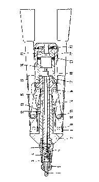
Figure 1 is a view in section of a hand riveting
apparatus for blind rivet nuts, and
Figure 2 is a modified view of the turning means in
section for an apparatus as shown in Figure 1.
In the hand riveting apparatus shown in Figure 1 for
blind rivet nuts, the screwthreaded mandrel 1 projects out of
the mouthpiece 2 which is fixed by means of a lock nut 3. The
screwthreaded mandrel receiving means 4 is disposed in the
front sleeve portion 5 in which the mouthpiece 2 is also
fixed. Fixing is effected by a rear lock nut 6. The handle
or gripping tubes 8 of the levers are secured by pins 9 to the
front apparatus housing 7. The front end of the tongs legs 14
is pivotally connected by means of a screwthreaded pin 10 and
a securing nut 11, while the rearward end thereof is fixed to
the apparatus with pins 9. A stroke setting screw 13 with O-
ring 12 is mounted to the front housing 7. The draw spindle
16 extends through the rear housing 15. A guide sleeve 18 is
mounted to the rear housing 15 by means of screwthreaded pins
17. A planetary transmission 19 is carried in the guide

4 -l~35~95
sleeve- 18 and fixed by the screwthreaded pins 20. Extending
from the planetary transmission 19 is an entrainment member 21
to which a rotary head 22 is fixed by screwthreaded pins 23.
When the rotary head 22 is turned, the planetary
transmission 19 is actuated by way of the entrainment member
21 and in turn causes the spindle 16 to rotate. In that way
it is possible, by rotation of the rotary head 22, to screw
the screwthreaded mandrel on to the blind rivet nut and to
screw it out again after the rivet setting operation.
Figure 2 shows a modified embodiment. Carried on-the
apparatus housing 14 is a sleeve 41 which is arranged to be
rotatable in relation to the apparatus housing. Provided in
the sleeve 41-is a bore 42 through which a fixing pin (not
shown) engages into an opening 43 provided in the apparatus
housing 40. In that way, by virtue of a multiplicity of
openings 43 which are distributed around the periphery of the
assembly, the sleeve 41 can be fixed in different positions in
relation to the apparatus housing 40. It is also possible
however to provide a frictional fit so that the sleeve 41 is
steplessly adjustable in relation to the apparatus housing 40.
Therefore, by means of the sleeve 41, a rotary head which is
disposed laterally thereon can be moved into a position
relative to the apparatus housing 40, as circumstances require
in the assembly operation or as is most acceptable to the
operator. Connected to the rotary head 44 is a bevel gear 45,
the shaft 46 of which extends perpendicularly to the draw
spindle 16.
The draw spindle 16 is connected to an extension spindle
47 carrying a bevel gear 48 meshing with the bevel gear 45 of
the shaft 46 to which the rotary head 44 is connected. The
rotary head is non-rotatably connected to the shaft 46 by
means of a pin or bolt (not shown) which is carried in a bore
49 in the rotary head. In that way, by means of the laterally
disposed rotary head 44 and by way of the draw spindle 16, the
mandrel 1 can be rotated in order to screw on the screw-
threaded rivet nut and to screw out the screwthreaded mandrel
1 after the riveting operation. The invention thus provides

~ O ~ 7 c
~ 5
an apparatus for setting screwthreaded rivet nuts wherein
rotary movement of the screwthreaded mandrel is effected in a
simple manner by means of the screwthreaded head 22, 44 and
the head 44 can be moved into an optimum position.

Representative Drawing
A single figure which represents the drawing illustrating the invention.
Administrative Status

2024-08-01:As part of the Next Generation Patents (NGP) transition, the Canadian Patents Database (CPD) now contains a more detailed Event History, which replicates the Event Log of our new back-office solution.

Please note that "Inactive:" events refers to events no longer in use in our new back-office solution.

For a clearer understanding of the status of the application/patent presented on this page, the site Disclaimer , as well as the definitions for Patent , Event History , Maintenance Fee  and Payment History  should be consulted.

Event History

Description Date
Time Limit for Reversal Expired 2007-02-06
Inactive: IPC from MCD 2006-03-11
Letter Sent 2006-02-06
Inactive: Late MF processed 1998-02-17
Grant by Issuance 1997-12-30
Inactive: Status info is complete as of Log entry date 1997-10-24
Inactive: Application prosecuted on TS as of Log entry date 1997-10-24
Pre-grant 1997-04-22
Notice of Allowance is Issued 1997-03-11
Request for Examination Requirements Determined Compliant 1994-10-20
All Requirements for Examination Determined Compliant 1994-10-20
Application Published (Open to Public Inspection) 1991-08-11

Abandonment History

There is no abandonment history.

Fee History

Fee Type Anniversary Year Due Date Paid Date
Registration of a document 1997-01-21
Final fee - small 1997-04-22
Reversal of deemed expiry 2004-02-06 1998-02-17
MF (patent, 7th anniv.) - small 1998-02-06 1998-02-17
MF (patent, 8th anniv.) - small 1999-02-08 1999-01-14
MF (patent, 9th anniv.) - small 2000-02-07 2000-01-28
Reversal of deemed expiry 2004-02-06 2000-01-28
MF (patent, 10th anniv.) - small 2001-02-06 2001-01-25
Reversal of deemed expiry 2004-02-06 2001-01-25
Reversal of deemed expiry 2004-02-06 2002-01-30
MF (patent, 11th anniv.) - small 2002-02-06 2002-01-30
MF (patent, 12th anniv.) - small 2003-02-06 2003-01-27
Reversal of deemed expiry 2004-02-06 2003-01-27
MF (patent, 13th anniv.) - small 2004-02-06 2004-01-29
Reversal of deemed expiry 2004-02-06 2004-01-29
MF (patent, 14th anniv.) - small 2005-02-07 2005-01-20
2005-01-20
Owners on Record

Note: Records showing the ownership history in alphabetical order.

Current Owners on Record
MASCHINENBAU SUBOTSCH VERWALTUNGS- UND BETEILIGUNGS-GMBH
Past Owners on Record
MANFRED SCHWAB
Past Owners that do not appear in the "Owners on Record" listing will appear in other documentation within the application.
Documents

To view selected files, please enter reCAPTCHA code :


To view images, click a link in the Document Description column (Temporarily unavailable). To download the documents, select one or more checkboxes in the first column and then click the "Download Selected in PDF format (Zip Archive)" or the "Download Selected as Single PDF" button.

List of published and non-published patent-specific documents on the CPD .

If you have any difficulty accessing content, you can call the Client Service Centre at 1-866-997-1936 or send them an e-mail at CIPO Client Service Centre.

({010=All Documents, 020=As Filed, 030=As Open to Public Inspection, 040=At Issuance, 050=Examination, 060=Incoming Correspondence, 070=Miscellaneous, 080=Outgoing Correspondence, 090=Payment})


Document
Description 
Date
(yyyy-mm-dd) 
Number of pages   Size of Image (KB) 
Representative drawing 1997-12-15 1 13
Abstract 1993-11-19 1 16
Drawings 1993-11-19 2 61
Claims 1993-11-19 2 57
Description 1993-11-19 5 209
Abstract 1997-03-10 1 17
Description 1997-03-10 6 226
Claims 1997-03-10 2 43
Drawings 1997-03-10 2 45
Late Payment Acknowledgement 1998-02-23 1 172
Maintenance Fee Notice 2006-04-02 1 172
Fees 1998-02-16 1 48
Fees 1997-01-28 1 66
Fees 1996-02-04 1 51
Fees 1995-01-30 1 61
Fees 1994-01-23 1 48
Fees 1993-01-28 1 37
Prosecution correspondence 1994-12-05 1 27
Examiner Requisition 1996-08-29 2 65
Prosecution correspondence 1996-12-29 2 79
Courtesy - Office Letter 1994-11-28 1 60
Prosecution correspondence 1994-10-19 1 40
Courtesy - Office Letter 1991-08-14 1 19
PCT Correspondence 1991-07-03 1 40