Sélection de la langue

Search

Sommaire du brevet 2035795 

Énoncé de désistement de responsabilité concernant l'information provenant de tiers

Une partie des informations de ce site Web a été fournie par des sources externes. Le gouvernement du Canada n'assume aucune responsabilité concernant la précision, l'actualité ou la fiabilité des informations fournies par les sources externes. Les utilisateurs qui désirent employer cette information devraient consulter directement la source des informations. Le contenu fourni par les sources externes n'est pas assujetti aux exigences sur les langues officielles, la protection des renseignements personnels et l'accessibilité.

Disponibilité de l'Abrégé et des Revendications

L'apparition de différences dans le texte et l'image des Revendications et de l'Abrégé dépend du moment auquel le document est publié. Les textes des Revendications et de l'Abrégé sont affichés :

  • lorsque la demande peut être examinée par le public;
  • lorsque le brevet est émis (délivrance).
(12) Brevet: (11) CA 2035795
(54) Titre français: APPAREIL A RIVETER
(54) Titre anglais: RIVETING APPARATUS
Statut: Périmé et au-delà du délai pour l’annulation
Données bibliographiques
(51) Classification internationale des brevets (CIB):
  • B21J 15/12 (2006.01)
  • B21J 15/04 (2006.01)
  • B21J 15/20 (2006.01)
  • B25B 27/00 (2006.01)
(72) Inventeurs :
  • SCHWAB, MANFRED (Allemagne)
(73) Titulaires :
  • MASCHINENBAU SUBOTSCH VERWALTUNGS- UND BETEILIGUNGS-GMBH
(71) Demandeurs :
  • MASCHINENBAU SUBOTSCH VERWALTUNGS- UND BETEILIGUNGS-GMBH (Allemagne)
(74) Agent: KIRBY EADES GALE BAKER
(74) Co-agent:
(45) Délivré: 1997-12-30
(22) Date de dépôt: 1991-02-06
(41) Mise à la disponibilité du public: 1991-08-11
Requête d'examen: 1994-10-20
Licence disponible: S.O.
Cédé au domaine public: S.O.
(25) Langue des documents déposés: Anglais

Traité de coopération en matière de brevets (PCT): Non

(30) Données de priorité de la demande:
Numéro de la demande Pays / territoire Date
G 90 01 315.8 (Allemagne) 1990-02-06

Abrégés

Abrégé français

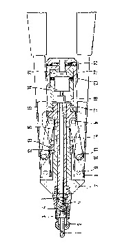
La présente invention vise une machine à riveter hydraulique ou manuelle comportant deux leviers pivotants servant aux opérations de rivetage proprement dites, et un mandrin fileté qu'on peut faire tourner pour poser un rivet. € l'autre extrémité du boîtier de l'appareil, opposée au mandrin, se trouve un dispositif d'actionnement de ce dernier, ayant la forme d'une tête rotative solidaire d'une tige de manoeuvre.


Abrégé anglais


In a hydraulically or manually operated riveting
apparatus having two pivotal levers for performing the actual
riveting operation and a screwthreaded mandrel which can be
caused to rotate the screwing on the rivet nut and for
screwing out after the rivet setting operation it is provided
at the rear end of the apparatus housing which is in opposite
relationship to the screwthreaded mandrel a turning means in
the form of a rotary head which is non-rotatably connected to
a draw spindle connected to the screwthreaded mandrel which
projects at the front end of the apparatus.

Revendications

Note : Les revendications sont présentées dans la langue officielle dans laquelle elles ont été soumises.


Claims:
1. A riveting apparatus, hydraulically operated or as a
hand-riveting apparatus comprising:
a housing;
two pivotal levers connected to said housing and
operationally connected to the apparatus for performing the
actual riveting operation;
a screwthreaded mandrel projecting at a front end of said
housing and which can be caused to rotate for screwing on the
rivet and for screwing out the rivet after the rivet setting
operation, a draw spindle connected to a rear end of said
screw threaded mandrel and extending through a rear end of
said housing, and a turning means in the form of a rotary head
arranged on the apparatus housing outside the plane of the
handle tubes and connected by way of a gear transmission means
to the draw spindle.
2. Apparatus according to claim 1 characterized in that the
rotary shaft of the rotary head extends in a plane
perpendicularly to the draw spindle and carries a bevel gear
meshing with a bevel gear carried on the draw spindle.
3. Apparatus according to claim 1 wherein said rotary head
is of a cylinder form.
4. Apparatus according to claim 1 characterized in that the
rotary head is mounted on a sleeve carried rotatably on the
rear end of the apparatus housing.
5. Apparatus according to claim 4 characterized in that the
sleeve can be fixed in different positions.
6. Apparatus according to claim 5 characterized in that the
sleeve carries a fixing pin which engages into openings
provided on the apparatus housing.

7. Apparatus according to claim 6 characterized in that the
sleeve is steplessly adjustable in respect of its rotational
position by a friction fit on the apparatus housing.

Description

Note : Les descriptions sont présentées dans la langue officielle dans laquelle elles ont été soumises.


Jo3579~
Riveting APparatus
The invention relates to a riveting apparatus having two
pivotal levers for performing the actual riveting operation
and a screwthreaded mandrel which can be caused to rotate for
screwing on the rivet nut and for screwing out after the rivet
setting operation.
A riveting operation can admittedly be carried out
without difficulties, with apparatuses of that kind, but it
requires a large number of handling operations which represent
stress for the operator, which in the course of prolonged
operating periods results in fatigue, while in addition the
performance of the individual handling operations requires a
great amount of time. Thus, firstly the lever arms have to be
completely opened and the screwthreaded mandrel has to be set
rotating. For that purpose it is known for a hand knob on a
draw tube mounted on the screwthreaded mandrel to be pushed
back while the riveting nut is screwed on the screwthreaded
mandrel, between the thumb and the index finger, on the
housing of the apparatus. The actual riveting operation is
performed by the two lever arms being pressed together
inwardly. Thereupon, by actuation of the draw tube, the
screwthreaded mandrel is screwed out of the rivet nut. In
order to make it easier to carry out the riveting operation,
it is already known to provide at the end of the screw-
threaded mandrel an electric motor which can cause thescrewthreaded mandrel to rotate. The electric motor with the
battery required for that purpose however means that the
apparatus is then of comparatively high weight so that moving
around with the apparatus is made more difficult as a result
and the operator has to apply a comparatively large amount of
force.
The invention is therefore based on the problem of
providing a riveting apparatus which permits advantageous
operation for carrying out the riveting operation, in which
fatigue on the part of the operator and the processing time
are reduced.
The invention provides that disposed at the rear end of

the housing of the apparatus, which is in opposite
relationship to the screwthreaded mandrel, is a turning means
in the form of a rotary head which is non-rotatably connected
to a draw spindle connected to the screwthreaded mandrel which
projects at the front end of the apparatus housing.
Thus, according to the invention there is provided a
riveting apparatus, hydraulically operated or as a hand-
riveting apparatus comprising a housing; two pivotal levers
connected to said housing and operationally connected to the
apparatus for performing the actual riveting operation; a
screwthreaded mandrel projecting at a front end of said
housing and which can be caused to rotate for screwing on the
rivet and for screwing out the rivet after the rivet setting
operation, a draw spindle connected to a rear end of said
screw threaded mandrel and extending through a rear end of
said housing, and a turning means in the form of a rotary head
arranged on the apparatus housing outside the plane of the
handle tubes and connected by way of a gear transmission means
to the draw spindle.
In order to reduce the force applied, the invention
further proposes that the rotary head is disposed in a
cylinder-like configuration around the rear end of the housing
apparatus and is connected to an entrainment means which
drives a transmission means arranged at the rear end of the
draw spindle.
Rotary markings are advantageously provided on the
apparatus housing.
For the purposes of improved operation, it may be
provided that the rotary head is arranged laterally on the
apparatus housing outside the plane of the handle tubes and is
connected by way of a gear transmission means to the draw
spindle. In that arrangement it is advantageously provided
that the rotary shaft of the rotary head extends in a plane
perpendicularly to the draw spindle and that the rotary shaft
carries a bevel gear meshing with a bevel gear carried on the
draw spindle.
V,

2a
In accordance with an advantageous embodiment the rotary
head is mounted on a sleeve which is carried rotatably on the
rear end of the apparatus housing, wherein the sleeve can be

::~03~79~
fixed in different positions in dependence on the mode of
operation of the apparatus.
For that purpose the sleeve advantageously carries a
fixing pin which engages into openings provided on the
apparatus housing. It may advantageously be provided that the
sleeve is steplessly adjustable in respect of its rotary
position by a frictional fit on the apparatus housing.
This apparatus can be adapted to the mode of operation by
the operator, is comparatively light and permits greater ease
of operation. The apparatus can be operated manually or
hydraulically. The apparatus is of comparatively low weight
and is shorter than known apparatuses, so that it can be
handled better, and it is distinguished by being of a compact
structure. It requires a comparatively small amount of force
to be applied.
The invention will be described in greater detail
hereinafter by means of an embodiment with reference to the
accompanying drawings in which:
Figure 1 is a view in section of a hand riveting
apparatus for blind rivet nuts, and
Figure 2 is a modified view of the turning means in
section for an apparatus as shown in Figure 1.
In the hand riveting apparatus shown in Figure 1 for
blind rivet nuts, the screwthreaded mandrel 1 projects out of
the mouthpiece 2 which is fixed by means of a lock nut 3. The
screwthreaded mandrel receiving means 4 is disposed in the
front sleeve portion 5 in which the mouthpiece 2 is also
fixed. Fixing is effected by a rear lock nut 6. The handle
or gripping tubes 8 of the levers are secured by pins 9 to the
front apparatus housing 7. The front end of the tongs legs 14
is pivotally connected by means of a screwthreaded pin 10 and
a securing nut 11, while the rearward end thereof is fixed to
the apparatus with pins 9. A stroke setting screw 13 with O-
ring 12 is mounted to the front housing 7. The draw spindle
16 extends through the rear housing 15. A guide sleeve 18 is
mounted to the rear housing 15 by means of screwthreaded pins
17. A planetary transmission 19 is carried in the guide

4 -l~35~95
sleeve- 18 and fixed by the screwthreaded pins 20. Extending
from the planetary transmission 19 is an entrainment member 21
to which a rotary head 22 is fixed by screwthreaded pins 23.
When the rotary head 22 is turned, the planetary
transmission 19 is actuated by way of the entrainment member
21 and in turn causes the spindle 16 to rotate. In that way
it is possible, by rotation of the rotary head 22, to screw
the screwthreaded mandrel on to the blind rivet nut and to
screw it out again after the rivet setting operation.
Figure 2 shows a modified embodiment. Carried on-the
apparatus housing 14 is a sleeve 41 which is arranged to be
rotatable in relation to the apparatus housing. Provided in
the sleeve 41-is a bore 42 through which a fixing pin (not
shown) engages into an opening 43 provided in the apparatus
housing 40. In that way, by virtue of a multiplicity of
openings 43 which are distributed around the periphery of the
assembly, the sleeve 41 can be fixed in different positions in
relation to the apparatus housing 40. It is also possible
however to provide a frictional fit so that the sleeve 41 is
steplessly adjustable in relation to the apparatus housing 40.
Therefore, by means of the sleeve 41, a rotary head which is
disposed laterally thereon can be moved into a position
relative to the apparatus housing 40, as circumstances require
in the assembly operation or as is most acceptable to the
operator. Connected to the rotary head 44 is a bevel gear 45,
the shaft 46 of which extends perpendicularly to the draw
spindle 16.
The draw spindle 16 is connected to an extension spindle
47 carrying a bevel gear 48 meshing with the bevel gear 45 of
the shaft 46 to which the rotary head 44 is connected. The
rotary head is non-rotatably connected to the shaft 46 by
means of a pin or bolt (not shown) which is carried in a bore
49 in the rotary head. In that way, by means of the laterally
disposed rotary head 44 and by way of the draw spindle 16, the
mandrel 1 can be rotated in order to screw on the screw-
threaded rivet nut and to screw out the screwthreaded mandrel
1 after the riveting operation. The invention thus provides

~ O ~ 7 c
~ 5
an apparatus for setting screwthreaded rivet nuts wherein
rotary movement of the screwthreaded mandrel is effected in a
simple manner by means of the screwthreaded head 22, 44 and
the head 44 can be moved into an optimum position.

Dessin représentatif
Une figure unique qui représente un dessin illustrant l'invention.
États administratifs

2024-08-01 : Dans le cadre de la transition vers les Brevets de nouvelle génération (BNG), la base de données sur les brevets canadiens (BDBC) contient désormais un Historique d'événement plus détaillé, qui reproduit le Journal des événements de notre nouvelle solution interne.

Veuillez noter que les événements débutant par « Inactive : » se réfèrent à des événements qui ne sont plus utilisés dans notre nouvelle solution interne.

Pour une meilleure compréhension de l'état de la demande ou brevet qui figure sur cette page, la rubrique Mise en garde , et les descriptions de Brevet , Historique d'événement , Taxes périodiques et Historique des paiements devraient être consultées.

Historique d'événement

Description Date
Le délai pour l'annulation est expiré 2007-02-06
Inactive : CIB de MCD 2006-03-11
Lettre envoyée 2006-02-06
Inactive : TME en retard traitée 1998-02-17
Accordé par délivrance 1997-12-30
Inactive : Renseign. sur l'état - Complets dès date d'ent. journ. 1997-10-24
Inactive : Dem. traitée sur TS dès date d'ent. journal 1997-10-24
Préoctroi 1997-04-22
Un avis d'acceptation est envoyé 1997-03-11
Exigences pour une requête d'examen - jugée conforme 1994-10-20
Toutes les exigences pour l'examen - jugée conforme 1994-10-20
Demande publiée (accessible au public) 1991-08-11

Historique d'abandonnement

Il n'y a pas d'historique d'abandonnement

Historique des taxes

Type de taxes Anniversaire Échéance Date payée
Enregistrement d'un document 1997-01-21
Taxe finale - petite 1997-04-22
Annulation de la péremption réputée 2004-02-06 1998-02-17
TM (brevet, 7e anniv.) - petite 1998-02-06 1998-02-17
TM (brevet, 8e anniv.) - petite 1999-02-08 1999-01-14
TM (brevet, 9e anniv.) - petite 2000-02-07 2000-01-28
Annulation de la péremption réputée 2004-02-06 2000-01-28
TM (brevet, 10e anniv.) - petite 2001-02-06 2001-01-25
Annulation de la péremption réputée 2004-02-06 2001-01-25
Annulation de la péremption réputée 2004-02-06 2002-01-30
TM (brevet, 11e anniv.) - petite 2002-02-06 2002-01-30
TM (brevet, 12e anniv.) - petite 2003-02-06 2003-01-27
Annulation de la péremption réputée 2004-02-06 2003-01-27
TM (brevet, 13e anniv.) - petite 2004-02-06 2004-01-29
Annulation de la péremption réputée 2004-02-06 2004-01-29
TM (brevet, 14e anniv.) - petite 2005-02-07 2005-01-20
2005-01-20
Titulaires au dossier

Les titulaires actuels et antérieures au dossier sont affichés en ordre alphabétique.

Titulaires actuels au dossier
MASCHINENBAU SUBOTSCH VERWALTUNGS- UND BETEILIGUNGS-GMBH
Titulaires antérieures au dossier
MANFRED SCHWAB
Les propriétaires antérieurs qui ne figurent pas dans la liste des « Propriétaires au dossier » apparaîtront dans d'autres documents au dossier.
Documents

Pour visionner les fichiers sélectionnés, entrer le code reCAPTCHA :


Pour visualiser une image, cliquer sur un lien dans la colonne description du document (Temporairement non-disponible). Pour télécharger l'image (les images), cliquer l'une ou plusieurs cases à cocher dans la première colonne et ensuite cliquer sur le bouton "Télécharger sélection en format PDF (archive Zip)" ou le bouton "Télécharger sélection (en un fichier PDF fusionné)".

Liste des documents de brevet publiés et non publiés sur la BDBC .

Si vous avez des difficultés à accéder au contenu, veuillez communiquer avec le Centre de services à la clientèle au 1-866-997-1936, ou envoyer un courriel au Centre de service à la clientèle de l'OPIC.

({010=Tous les documents, 020=Au moment du dépôt, 030=Au moment de la mise à la disponibilité du public, 040=À la délivrance, 050=Examen, 060=Correspondance reçue, 070=Divers, 080=Correspondance envoyée, 090=Paiement})


Description du
Document 
Date
(aaaa-mm-jj) 
Nombre de pages   Taille de l'image (Ko) 
Dessin représentatif 1997-12-15 1 13
Abrégé 1993-11-19 1 16
Dessins 1993-11-19 2 61
Revendications 1993-11-19 2 57
Description 1993-11-19 5 209
Abrégé 1997-03-10 1 17
Description 1997-03-10 6 226
Revendications 1997-03-10 2 43
Dessins 1997-03-10 2 45
Quittance d'un paiement en retard 1998-02-23 1 172
Avis concernant la taxe de maintien 2006-04-02 1 172
Taxes 1998-02-16 1 48
Taxes 1997-01-28 1 66
Taxes 1996-02-04 1 51
Taxes 1995-01-30 1 61
Taxes 1994-01-23 1 48
Taxes 1993-01-28 1 37
Correspondance de la poursuite 1994-12-05 1 27
Demande de l'examinateur 1996-08-29 2 65
Correspondance de la poursuite 1996-12-29 2 79
Courtoisie - Lettre du bureau 1994-11-28 1 60
Correspondance de la poursuite 1994-10-19 1 40
Courtoisie - Lettre du bureau 1991-08-14 1 19
Correspondance reliée au PCT 1991-07-03 1 40