Note: Descriptions are shown in the official language in which they were submitted.
WQgl/~708` PCT/US90~3~68
2Q3~897 ~
9 AN AIR CI,EANING UNIT
11
12 This application is a continuation-in-part of
13 application serial no. 378,088 filed ~uly 11, 1989.
14
15 Backqround of the Invention : :
16
17 This inv~ntion relates ~o a~ air cleaning lunit,
18 and more particularly to an air cleaning unit which
19 ¢an effectively remove pollutants ~rom the air, is
20 relatiYely compact, can be powered by a standard
21 electrical socket and which can have other functions
22 as:well, such as light illumination~ and the dispensing
23 of fixed amounts of:fragrance into th~ air.
24 Numerous patents have issue~ in which air cleaning
25 units are taught and described. These teachin~s~ are
26 documented in, ~or example, U.S. Pat. No. 4,375,642
27 issued March lS, 1983 to Bio~ech Electronics ~td.~
28 U.S. Pat. No. 3,7~5,560 issu~d May 2~, 1973 to D.C.
29 Wellman: U.S. Pat. No. 3,783,5~ issued Ja:nuary 8,
30 1974 to M. Hundis; U.S. Pat.~No. 3,86~,8~4 :issued
31 January 21, :1975:: to R.C. Marsh;~ U.S. :Pat.~ No.
32 4,114,082 i~ssued September 19 t ~ :1978 ~to J~H. Newell;
33 U.S. Pat. No. 4,133,653 issued January 9, 1~79 to C.W.
: : :
: ` : : : ` : `~ :: : :
`WO9l/0~708 2 ~ ~ 5 ~ ~ 7 P~T/US90/03g68
2-
1 SO1tiS; U.S. Pat. NO. 4,215,682 iSSUed AUgUSt 1980 tO
2 KUbik et. a1.; U.S. Pat. NO. 3,744,216 iSSUed JU1Y 10,
3 1973 tO Ha11Oran: U.S Pat. NO. 3,841,840 iSSUed
4 OCtOber 15, 1974 tO HUndhaUSen; U.S. Pat. NO.
5 3,587,210 iSSUed ~Une 28, 1g71 tO Shriner: U.S. Pat.
6 NO. 4,133,652 iSSUed JanUarY ~, 1979 tO IShikaWa
7 et. a1.: U.S. Pat. NO. 3,191,362 issued June 29 , 1965
8 to Bourgeois; U.S. Pat. NQ. 3,853,529 iSSUed December
9 10, 1974 to BOOthe et. a1.; U.S. Pat. NO. 3,828,530
10 issued August 13, 1974 to Peters; U,S. Pat. ~o.
11 3,86~,404 iSSUed January 14, 1975 ~O JQChimSki: U.S.
12 Pat. No. 2,790,510 issued ~pril 30, 1957 to J.G.
13 Brabec: U.S. Pat. No. 4,261~,712 issued Apr 1 14, 1981
14 tQ Kinkade, U.S. Pat. NO. 3,804,942 issued Apr,il 16,
15 1974 to Takaskhi: U.S. Pat. :No. 4,252,S47 issued
16 February 24, 1981 to Johnson; German Pat No. DT2732859
17 issu~d February 1, 1979 to Wagner; French Pat~ No.
18 1,193,100 issued October 30, 195g; and~ U.S.5.R.: Pat.
19 No. 606,602 issued May 25, 197~. Pat. No. 4,069,026
20 issued JanUarY 17, 1978 to Sim et. al~ t~aches a
21 method for producing electrosta~cally spun fibers.
22 COnVentiOna1 ~ir cleaning units are, for the most
23 Part, limited to aCCOmP1iShing only certain air
24 fiItering or purifying tasks,:large apparatus' that:
25 cannot easily fit Within : the available space,~ and
26 cannot be employed ~o PerfOrm anything~ other than
27 certain particular limited functions~
28 It would be adVan~ageOUS, and an improvement over:
29 prior art air cleaning units, to have~an~ai~ cleaning
3io lunit whIc~h can effectively fi1ter and puri~y air, is
31 relatively compact, is ~ powered~: by: a s~tandard
32 eIectrical socket and which~can have other functions,~
33:such :as light~ illumination~ and~the::~dispensing of ;
W~91/00708 2 ~ ~ 5 ~ ~ ~PCT/US90/03968
..... .
. 3 ~ :
1 controlled amounts of fragrance into the air. No air
2 cleaning u~it tau~ht by the prior art can accomplish
3 all of the following tasks: collect particles,
4 sterilize air, act on organic gases i~cluding carbon
5 monoxide and remove poisonous gases from th~ air, in
6 addition to providing light and dispensing fragrance.
7 The air cleaning unit of this invention accomplishes
8 all of these tasks effectively.
9 This improvement is achi~v~d by passing air to be
10 purified through a new filtering means in the air
11 cleaning unit which filtering means comprises a means
12 for creating an electromagnetic fiel*. The filt,ering
13 means is adapted to collect particles, namely, dust,
14 pollen, cigaret~e smoke and ~ther submicron
15 particulate contaminations, and to oxidize and ionize
16 certain substances in the air namely, fumes and
17 po}lutants. A light source, contained in one
18 embodi~ent of the unit, which has a wide wavelength
19 spectrum (i~, it has frequence~ fro~ far UVoC ~o far
20 Infra Red) further enchances ~he effectiveness of the
21 unit by emitting heat and W waYel2ngths. The heat
22 causes varioUs reactions occurring in the unit to move
23 forward more rapidly. The UV wavelengths have
24 germicidal properties to destroy and kill
25 microorga~isms.
26
Z7 S~m~-E~ of the Invention
28
: 29 The present invention is direc~ed ~o providing an
~: 30 air cleanin~: unit which can effectively remove
~ 31 pollutants from the air,: is relatively compact, is
1 32 power d by a standard electrical socket, and which can
~ 33 have other func~ions as well, such as light
:~ :
i
. ~
WO9l/~0708 PCT/US90/03968
20358~ ~
l illumination and the dispensing of fixed amounts of
2 fragance into the air.
3 In an illustrative embodiment of the invention
4 the filter means comprising an electromagnetic field
5 created by current flowing along a coiled wir~ and
6 further comprising a new filter, in combination with a
7 light source, create an environment in a housing,
8 forming a semi-enclosed volume, which effectively
9 filters and puri~ies air passing through the air
lO cleaning unit by removing particula~es and by
11 oxidizing or breaking certain pollutan~s in the air to
12 less harm pollutants. The air is moved across the
13 filter means by a fan means contained within the body
14 of the housing.
16 Brief ~escription of the Draw~ng~
17
18 The oregoing and other features of the present
19 invention will be more readily apparent from the
~0 following detailed description of the invention in
21 which: ~ ~
22 Fig. 1. is an exploded cross-sectional view of the
23 housing of the air cleaner unit:
24 Fig. 2. is an exploded view, partially ~in
25 cross-section, of the internal componen~s of the air
26 cleaning unit;
27 Fig. 3. is an exploded view of~ partially in
28 cross-section, of ~he housing of the air cleaner unit
29 and of the layout thereof, showing~ how said ~components
30 fit within said housin~
31 Fig. 4~-. and ~ Fig. 5 :~are sectional views of
32 preferred embodiments of a filter which can;be used in
33 the air cleaning unit;
WO91~070~ 2 ~ 3 ~ 8 9 ~CT/US9OJ03968
-5~
1 Fig. 6. is a perpec~ view of a light source
2 used in the air cleaning unit and wire coiled around
3 said light source, said coiled wire being in parallel
4 with sa id sour~e:
Fig. 7. is a perspective view of a light source
6 and wire coiled around ~aid light source, said coiled
7 wirQ being in parallel with said ligh~ source, and
8 said coiled wire having an addi~ional coil in series:
9 Fig. 8. is a perspective view of a light source
10 used in the air cleaning unit and a wire coiled ar~und
ll said li~ht source, said coiled wire being in series to
12 said light source;
13 Fig. 9. is a perspective view of a ligh~ source
14 and wire coiled around said light source, said coiled
15 wire being in series wi~h sai~ light source and said
16 coiled wire having an additional CQil in series;
17 Each of Figures 6-9 show a base upon which the
18 light source and coiled wire can be located.
19 Fig. lO. is a top view of one embodiment of the
20 printed circuit upon which a light source, coiled wire
21 and ~asP are located;
22 Fig~ ll. is a cross-sectional view of a fragrance
23 dispensor to be used with the air cleaning unit at any
24 strategic location in ~he air cleaning unit;
Fig. l2. is a top view of said ~ragrance dispensor,
26 Fig. 13. is a bot~om view of th¢ base of said
27 fragrance dispensor,~ and ~ ;
28 Fig. 14, is a cross-sectional view of ~he~
2,9 fragrance~ dispensor and ~ilter, showing how said
30 fragrance dispensor can be adapted to ~it into a
31 filter used in the air cleaning unit.
32 Fig. 15. is a cross~sectional view, partially in
33 section, of the air cl~ning unit.
34
J
'
~!
.
WOgl~00708 ` ' ; PCT/US90/03968 ~
2 ~ ~ ~ 8 9 ~ ~6~
l Descriptlon Of Illustrative Embodiments
3 Figure l shows the external structure of the air
4 cleaning unit. Upper housing 20 contains perforations
5 22 for the passage of air into or out of chamber 24
6 located in thP upper housing. Upper housing 20 is
7 detachably engaged with mid~housing 30. Mid-housing
8 30 forms a cylindrically shaped chamber 32 open from
9 both sides. Mid-housing 30 is detachably engaged with
lO a frusto-conical shaped lower housing 40 with neck
ll 41. Lower housing 40 has perforations 42 for the
12 passage of air out of or into the lower housing. Neck
13 41 is adapted to fit into socket 50. Socket 5Q, wi~h
14 threading 52, i5 a conventional light bulb socket
15 which can be screwed into a conventional light
16 fix~ure.
17 Upper hou~ing 20, mid-housing 30 and lower housing
18 40 are made of a transparent, or semi-transparent,
l9 material such as plastic or glass which is
20 contaminated with W absorbant material, which,
21 however, allows other light w~velengths to pass
22 through the material, to iIluminate the area. The
23 ideal material is an unbreakable plastic with high
2q resistance properties to prevent electric shock. The
25 number o~ housing parts contained in the air cleaner
26 unit housing can, of course, vary. ,The multi-part
~7 housing permits any combination o~ colors ~o be used
28 ~or the housing, that is, each part of the housing may
29 have a different color. It also allows con~rol of the
30 'color of the light :emitted from the air cleaning unit.
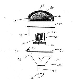
31 Figure 2 depicts the internal components of the
32 air cleaning unit. A preferred embod:iment of ilter 60
33 contains wire ;m~sh 62, which is a conductive material,
wo 91/00708 2 0 3 5 ~ ~ ~ PCT/US90/03968
f``.```
_7_ ; !; .
l p~ferably iron, and activa~ed carbon granuals 64
2 erl~ased in said wire mesh 62. On the top end of
3 filter 60 there can be a sponge-like material 66 which
4 can contain a means which acts as an indicator by
S changing color when the filter needs to be replaeed.
6 Sponge-like material 66 can also simply be coated with
7 said color indicating means. Fil~er 60 can have any
8 shape ~ut a shape which fits within and is
9 co-extensive with chamber 22 of upper housing 20 is
10 preferred. Filter 60 sits on holder 70, which holds
ll filter 60 in position within upper housing 20. Holder
12 70 is adapted to allow air to freely ~low into or out
~ 13 of chamber 32 of mid-hoùsing 30. Holder 70 has a
14 vertical extension 72 whose lower end is in contact
15 with switch activator 96 located on switch 94 in the
16 operating air cleaning unit. When vertical extension
17 72 is in contact with switch activator 96, the switch
18 is closed and electric current can pass through switch
19 94. If vertical extension 72 is moved from such a
20 position, such as when the air cleaning unit is taken
21 apart, switch 94 is opened and ~urrent ceases to flow
22 past the switch. This prevents electric shock and is
,5 23 an important safety feature.
24 Figure 2 also depicts coiled wire 8~ and light
~ 25 source 84, both positioned on base 86. Base 86 is a
1 26 heat resistant cera~ic-like material~ ~ase 86 is
27 positioned on printed circuit 90. Swi~ch 94 and
~ 28 ~witch activator 96 are also posi~ione~ on printed
i 29 circuit 90. Printed circuit 90 is located above fan
30 ioo comprising impeller 102 and motor 104 for
31 operating the fan. Motor 104 has electrical wires 106
~l 32 for connectin~ it to current. The motor op~rates on
!,~: 33 either high or low voltage and on either AC or DC
i:
~}~
~;~
, ~ .
WO91/007~8 - `' . PCT/~S9~/03~68
21~3~8~7 ~
1 power. The fan have one or more impellers 102 which,
2 when circulating, move air ~rom perforations 22 in
3 upper housing 20, through chamber 22 and then through
4 chamber 3~, into lower housing 40, and finally out of
5 per~orations 42 located in lower housing 40, or vice
6 versa.
7 Figure 3 depicts both the internal and external
8 component~ of the air cleaning unit and how they are
~ positioned relative to each other. Motor 104 fits
10 into neck 41 of lower housing 40. Neck 41 fits into
11 socket 50. Fan 100 fits entirely into the chamber
12 formed by lower housing 40. F~n 100 should be
13 positioned as low as possible inside lower housing
1~ 40. Impellers ~02 are designed for maximum efficiency
15 within the chamber formed by lower housing 40.
1~ Printed circuit 90 is adapted to fit on the upper end
17 of lower housing 40. Switch 94, base 86, light
18 element 84 and coiled wire 82, all of which sit on
19 printed circuit 90, are located in chamber 32 of mid
20 housing 30. Holder 70 is adapted to fit on the upper
21 end o~ mid housing 30. Filt~F 60, which sits on
22 holder 70, is loca~ed in chamber 22 formed by upper
23 housing 20. Alternati~ely, the filter may be held in
24 place by any attachment means in th~ upper housing,
25 and vertical extension 72 can protrude from the upper
26 housing, thereby obviating ~he need for~holder 70.
27 In a preferred embodimen~ of the invention, air is
28 puri~ied as ~ollows: air is drawn through perforations
29 22 into filter 60 by the movement of impellers 102.
30 Activated icarbon 64 in filter 60 absorbs certain
31 pollutants and reacts with other pollutan~s, The
32 efficiency of the acti~ated carbon to react with
33 pollutants is increased by the hea~ emitted from a
34 light source, this is especially the case when the
WO9l/~0708 ~ 0 3 ~ 8 9 7 PcT/us9o/o3968
1 ~cti~ated carbon works by chemically reactin~ with the
2 pollutants. Wire mesh 62 in fil~er 60 blocks
3 particles. More particles are blocked when the wire
4 mesh has a higher density. Wire mesh 62 can ~e any
5 metal or metal oxide, but is ideally iron, zinc oxide
6 or copper oxide. Sponge-like material 66 on top of
7 filter 60 is designed to collect fine particles and to
8 contain a color indicator m~ans which tells the user
9 when filter 60 needs to be replaced. The purification
10 of air by filter 60 is enhanced by induced current in
11 the wire mesh caused by the electromagnetic field
12 creating means and also by heat emitted from the light
13 source. That is, the induced current in wire mesh 62
14 and heat catalyze oxidation and other chemical
15 reactions in ~ilter 60, thereby allowing ~or thP
}6 conversion of certain poisonous gases into less
17 harmful gas. Thus, reactions such as the following
18 take place: CO + H2O ~ ~ H2 ~ CO2. The reaction
19 rate is increased by wire mesh 62, which acts as a
20 catalyst, as follows:
21 CU
2 2 C0 + 1/ 2 2 ~ C02; S02 .
23
24 Additionally, the induced current in wire mesh 62
25 improves the a~ility of activated carbon ~4 to react
26 with gases.
27 As air passes out of filter 60 and enters mid
28 housing ::hamber 32, certain W radiation wavelengths
29 emitted by light source 84 kill microorganisms. Heat
30 in chamber 32 generated by light source 8~ increases
31 the efficiency of the W wavel~ngths on microorgan-
32 isms. Additionally, W waveleng-~.s and heat. catalyze
33 oxidation and other :chemical reactions in the air
34 cleaning unit. For instance, the following reaction
'~
`, ~
1~ ,
WO9l/~0708 . PCT/US90/03968
2~'3~8~7 -10- ' ~
l.takes place under the conditions found in chamber 32:
2 2NO2 + W ~ heat - > 2N0 + 2 Heat also catalyzes
3 reactions such as 2O3 + Heat ~ 32~ Heat in
4 chamber 32 also increases the ioniza~ion of gases,
5 thereby increasing the effect that certain UV
6 wavelengths have on microorganisms and increasing
7 oxidation reactions.
8 The current flowing throu~h coiled wire ~2 causes
9 an electromagnetic field around the coil. The
10 electromagnetic field causes ionization of gases.
11 Furthermore, the electromagne~ic field causes current
12 to be induced in wire mesh 62 of filter 60. That is,
13 the current flowing through coiled wire 82, by
14 inductlon, causes induced current to flow in wire mesh
15 62 of filter 60. Ionization caused in chamber 32 and
16 at and around filter 60 have at least two major
17 purposes: 1) ionization per se causes the breakdown
1~ of certain harmful pollutants and 2) ionization of
19 gases increases the rate of oxidation. The efficiency
20 of the air cleaning unit can be increased ~y
21 increasing the frequency of the curren~ (such as by
22 chopping AC voltage). This is so because increased
23 current causes an increase in the electromagnetic
24 field, thereby increasing ionization of air. It
25 should be noted that air purification occurs in ~wo
26 stages -- at chamber 24 which contain~ filter 60 and
27 at cha~ber 32. The purified air is forced out o~ the
28 housing through perforations 42.
29 Figure 4 depicts one of many possible filters that
30 can be used with the air cleaning unit, ~his filter
31 being a preferred filt2r. The filter comprises a wire
32 mesh 62 and activated carbon ~4 contained within said
33 wire mesh. The wire mesh 62 and activated carbon are
,
:
WO91/00708 2 0 ~ ~ ~ 9 7 PCT/US90~03968
1 encased in a screen net of metal fibers 68. A
2 sponge-like material 66 is locat~d on the top
3 semicircular portion of fil~er 60. The sponge-li~e
4 material may be impregnated or coated with a means
5 which acts as an indicator and changes color when the
6 filt~r needs to be replaced. The indicator means may
7 be located in any location within the housing of the
8 air cleaning uni~ or it can even be a~tached to the
9 outside structure of ~he housing. Sponge-like
10 material 66 has electrical isola~ed properties and is
11 cover~d with casing 69 made of nonconductive isola~ed
12 fibers.
13 Figure 5 depicts another possible filter
14 comprising a wire mesh 62 and activated carbon 64
15 contained therein, all encased in a screen net of
16 metal fibers 68. In even another embodiment not shown
17 in the drawings, filter 60 can consist of activated
18 carbon 64 attached to acrylic fibers, said acrylic
19 fibers being in a shape similar to wire mesh 62. The
20 activated carbon and acrylic ~ilters are enclosed in a
21 net of acrylic fibers. Alte~atively, the acrylic
22 ~ibers, both in the m~sh and in the net, can also be
23 coated with catalizing materials such as me~al
24 oxides. Moreo~er, catalytic materials in the form of
25 ~ranuales can al50 be at~ached to the acryllc fibers.
26 Filter 60, of course, can consist of any combina~ion
27 of wire mesh, acrylic fibers and coated acrylic
28 fibers. The shape of the filter is ~ariable. It can
29 even be shaped to have a donut-shaped hole which
30 permits insertion of a fragrance dispenser within the
31 hole, as sho~n in Fig. 14.
32 Figure 6 shows one of four possible elec~rical
33 configurations of coiled wire 82 and light source 84.
34 Figures 6 and 7 show light sou~ce 84 and coiled wire
,
, ~
.
.. ,.~ ., ~ .. ~ ,,, !
WO9l/0070~ '~ ; PCT/~S90/03968
:. -12-
2Q3~89~ -
- l 82 connected in parallel. Pins 87 connect the coiled
wire to a current source. Pins 89 connect the light
3 source to a curren~ source. Figure 7 differs from
~ Fig. 6 in that it contains an additional coiled wire
5 88 in ~eri~s. Additional coiled wire 88 increases the
6 electromagnetic ~ield created because current flows
7 throuqh each of coiled wire 82 and coiled wire 88,
8 thereby increasing the induction occurring in the air
9 cleaning unit. Fi~. 8 and Fig. 9 show coiled wire 82
10 and light source 84 conn~cted in series. Thus pins 87
11 and 89 connect both the coiled wire and light source
12 to a current source~ Fig. 9 differs from Fig. 8 in
13 that it contains an additional coiled wire 88 in
1~ series for the same purpose as that shown in Fig. ~.
A preferred embodiment of light source 84 is a
16 replaceable halogen bulb because it emits a wide
17 spectrum of wavelengths and a great amount of heat. A
18 halogen bulb is also preferred because of its small
19 dimension, long life expectancy and high ratio of
20 light/power to save energy. As can be seen, coiled
21 wire 82 surrounds light source.~ 84. The number of
22 turns in the coil are variable and are calculated to
23 a~sorb the maximum hea~ from the bulb and to allow
24 maxi~um illumination from the bulb. Coiled wire 82
25 serves many purposes. It absorbs heat thereby
26 protecting the housing of the air cl~aner uni~ and
27 other components from over-heating. It also serves to
28 cool light source 84. It protects the air cleaning
29 unit from ele tric surges. It prolongs the lifetime
' I 30 o~ light source 84 because the coiled wire resists
; 31 quick current changes~ which occur when one switches
32 the light on and of. It creates an electromagnetic
33 field in chamber 32, which causes ionization of gase.~
': :
:
WO 91/00708 - - ~ 3 ~ ~ 9 ~ Pcr/usgo/03g68
, .,1`.~
13 . !`.~.,
.
1 in chamber 32 and which catalyzes oxidation and other
2 reactions in chamber 32. It also induces current in
3 wire m~sh 62 of filter 60. The induced current in
4 wire mesh 62 ionizes gases and also thereby catalyzes
5 oxidation and other reactions in chamber 24. Coiled
6 wire ~2 can be made of many different metals but the
7 preferred metals are nickel and copper. These two
8 metals are particularly effective catalystc for the
9 reactions which take place in the air cleaning unit.
10 Coiled wire 82 can also be made of any substance and
11 then simply coated with a substance which will act as
12 a strong catalyst. The surface of coiled wire 82 can
- 13 be smooth. In a preferred embodiment, however, the
14 surface of coiled wire 82 is rough. A rough surface
lS has a larger surface area which absorbs more heat. A
.l6 rough surface also has sharp angles which increases
17 the electromagnetic field and thereby the ionization
18 in the air surrounding the coiled wire.
19 Figure 10 depicts a top view of printed circuit
20 90, also shown in Figures 2 and 3. Apertures 92 are
21 adapted to permi~ pins 87 an~ 89 to connect to a
22 current source. ~pertures 98 are adapted to permit
23 switch 94 to connect to a curr~nt source.
24 The air cleaning unit can be made with or without
25 an optional fragrance dispenser. Figure 11 shows a
26 housing for dispensing fragrance into ~he air that is
27 passing through the air cleanin~ unit~ Figure 12
28 ~fhows a top view of cover 120 of said fragrance
f 29 housing having an air regulator means 122 which
30 regulates ~he passa~e of air into fragrance chamber
31 132. As cover 120 is ro~ated to the right, opening
l~ 32 124 becomes wider over space 131 in the upper portion
3~ 33 136 of ~ragrance hou ing 130, t~us permittiny a larger
f:
't;
f;
f`~
f~
t~
WO91/00708 PCT/US90103968
~ ~ 3 S 8 ~ - 14~
1 amount of air into fragrance chamber 132. A larger
2 amount o~ air in ~ragrance chamb~r 132 causes
3 fragrance to move into capillary pipe i34. Thus, the
4 amount of fragrance dispensed can be regulated in
5 controlled measured amounts. The fragrancP moves
6 through capillary pipe 134 into base 140 in the lower
7 portion of fragrance housing 130. Figure 13 shows a
8 bottom view of base 140. Sponge-like material or
9 other absorbant material 142 absorbs the fragrance
10 traveling through capillary pipe 134. As air passes
11 through the air cleaner unit, it comes into contact
12 with sponge-like material or other absorbant material
13 142 containing fragrance causing diffusion of
14 fragrance into the air. Thus, the air which passes
15 out of the air cleaner unit through perforations 42
16 can contain fragrance. Although fragrance housing 130
17 can be located a~ various strategic places within the
18 air cleaning unit, in the pre~erred embodiment of the
19 invention, fragrance housing 130 is located within
20 ~ilter 60. Threading 138 lodges fragrance housing 130
21 securely into place.
22 As can be seen in Figure 14, fragrance dispenser
23 130 is positioned in filter 60 so that air can pass
24 into openin~ 131 and so that sponge-like material or
25 other absorbant material 142 i5 exposed to air passing
26 out of filter 60, to permit diffusion o~ ~ragrance
27 into the air. Fragrance dispenser 130 can be made
28 with the same material used in making the housing for
29 the air cleaning unit.
l Figure,15 is a cross-sectional view~ par~ially in
31 s~ction, of the air cleaning unit described above.
32 While the invention has been par~icularly shown
33 and described with reference to preferred embodiments
W~91/00708 ~ 0 3 5 ~ 9 ~ PCT/usgo/o396~
. }5
l.thereof, it will be understood by th,ose skilled in the
2 art that various changes in ~orm and details may be
3 mad~ therein without departing from the spirit and
4 scope of the invention.
.
.
: ~ : :
';,~; ; ~