Note: Descriptions are shown in the official language in which they were submitted.
;~C3~
ACOUBTIC nT~-27~ V~RT~RTT~ Ol'~IGIN,
vDVT~RT.R ~parr ~r~NNING gy~rr!M
Ba~k4L~,u--d of the Invention
This invention relates to ultrasound diagnostic
scanning where ultrasonic energy illuminates internal
organs of the human body in real time and echoes received
from the so~t organ tissues or from moving scatterers are
tr~nc~ into electrical signals and then processed to
form two-dimensional cross-sectional images that are
1~ displayed upon a TV monitor or like display device.
Ultrasound medical systems known as phased
arrays have been used f or some time and have been
described, for example, in U.S. patents 4,140,022 and
4,550,607. Two basic scan and display formats have
generally been used in combination with planar linear
tr~ncdl~er arrays, that is arrays in which the face of
individual tr~n~ cC~r elements are positioned in a plane
parallel to each other and generally have uniform element
spacing .
Two-dimensional images have been formed by
linear scanning where ultrasonic beams on parallel
acoustic lines normal to or at an angle to the face of a
trAnC~ r~r array are propagated by single transducer
alements or by selected groups of tr~nc~ r elements
shifted across the array. Linear cc~nn;n~ with parallel
lines has the field of view det~rm;n~-l by the physical
aperture of the transducer array. For such a format, the
width of the field of view (FOV) is equal to the
tr~nC~-lc~r width for all scan depths. Thus, the field of
view in the linear scanning format is defined completely
by the physical characteristics of the array and is
limited by the physical edge of the array. A large field
of view requires a large physical aperture of active
~3~
trAn~ r elements which may create problems of access
and good skin contact.
The other scan and display format which is
typically used ~or planar linear trAnSul~lcor arrays is a
6ector. In a sector format, the elements are spaced much
closer together, typically at half-wavelength or so
intervals. This permits the acoustic scan lines to be
steered without generating grating lobes and allows both
the size of the trAn~tlcpr array to be decreased and the
field of view to be increased. For example, for a 90-
sector, the field of view at a scan depth D is given by
FOV = 2D. Typical scan depths range from 6 cm to 24 cm
and are user selectable. Sector phased arrays form
acoustic scan lines effectively all originating from the
center of the face of the trAne~ r array. The
allowable scan angle is a function of the spacing of the
individual trAn~dllc~r elements relative to operating
frequency. As a consequence, the field of view is also
largely defined by the physical characteristics of the
2C array and the field of view vanishes to zero at the face
of the array, itself.
A "trapezoidal" sc~nn;n~ and display format has
been described in U.S. patent 4,664,122, which is
specific to a particular planar linear array
construction. It consists of three sub-arrays, including
a central sub-array with substantially larger element
spacing, and two end sub-arrays with substantially
smaller element spacing. There is a fixed relationship
between the element spacing of the central sub-array
compared to the end sub-array such as a factor of 2.
Acoustic scan lines emanating ~rom the central sub-array
and from portions of the two end sub-arrays are parallel
.~
- 2036061
to each other, are perpQn~liclllAr to the tr~nqd~lcQr face,
and are consistent with a linear scan format. Acoustic
scan lines emanating from a single point on the face of
each end sub-array comprise a left-half and right-half
sector. The described end sub-arrays have smaller
element spacing, approximately one-half of the trAn~ Qr
wavelength, in order to permit steering the acoustic
beams out to angles of approximately 45- with acceptable
performance .
Since most transducers which are designed for
medical ultrasound imaging systems have uniform element
spacing, this "trapezoidal" s~Annin7 technique is not
advantageous because it does require special transducers
with non-uniform element spacing. TrAnc~ cPrs which are
specifically designed for this format are typically
larger than those clQ~lqnQA for "sector" q--Ann;n~. The
trapezoidal scan format is described as a compromise
between linear and sector srlnnin~, having the advantage
of steering, but with the disadvantage of increased
tr~ncd-l~ Qr size. This size disadvantage is inherent
because the increase in the field of view of the
displayed image compared to a sector image is increased
only to the extent that the transducer is increased in
size over that for a corrPCp~-n~ 1 n~ sector trAnC~l7~Pr.
The scan format also is specifically linked to the
trAnq~ cQr array construction in contrast to the
invention disclosed herein where the scan format i5
alterable under software control in order to optimize it
for different imaging applications using the same
trAnc~l~lt Qr ~Q~ ~ry~
The physical characteristics of curvilinear
arrays also define a field of view which is limited by
acoustic lines normal to the face of the array at the end
trAnc~llcQr elements. The field of view can be increased
~ 4 ~3~'~'6~
by a smaller radius of ~;ULVa,l_UL~ owever, resolution is
impaired and thereby degraded as compared to a less curved
array. Also, a large field of view in the near-field
requires a large aperture of active tr~n~ Qr elements.
A large field of view in the far-field requires some
combination of a large aperture and/or a smaller radius of
~:UL VcltULe: with the attendant loss of resolution.
All the foregoing formats, as well as mechanical
and waterpath scanning, have the field of view defined
completely by the physical characteristics of the array.
In none of these prior art s~nn;ng formats is the field of
view QYp inrl~Qd by situation-~9QrQnrlQnt software control.
rv of the Invention
In accordance with the invention, there is
provided a method for scanning an array of individual
tr;~ncr~ Qr elements for obtaining image, velocity or
variance data from a section of a body comprising the steps
of: ~r~ay~ting acoustic ~L~S;~ULC: waves into the body from
at least one active transmit aperture of individual
tr~nC~l11rQr elements; and receiving acoustic echoes on a set
of acoustic lines the centers of which are spatially non-
overlapping, including the step of steering the angle of
each acoustic line relative to the array, using for each
line a variable active aperture of individual tr~ncd~lcQr
elements which selectively includes only some or all
elements of the array, so that an extension of the acoustic
line in space beyond its origin at the array passes through
a substantially common vertex which is not located on the
tr~nc~11rQr array.
In another aspect of the invention, there is
provided a method for sc~nn1n~ an array of individual
tr;~ncd11cQr elements for obtaining image, velocity or
variance data from a section of a body comprising the steps
of: propagating acoustic p~ UL~ waves into the body from
at least one active transmit aperture of individual
tr~n~-lllrQr elements; receiving acoustic echoes on a set of
~ 203606 ~
acoustic lines the centers of which are spatially non-
overlapping using for each line a variable active aperture
of individual tr~n~ car elements which selectively
;n~ c only some or all elements of the array; shifting
5 on transmission or reception each acoustic line to
originate from an arbitrary origin relative to the center
of the face of said trAn~llcar array: and steering on
transmisaion or reception each acoustic line at an
arbitrary angle relative to the face of the array; whereby
10 an extension of the acoustic line in space beyond its
origin at the array passes through a substantially common
vertex which is not located on the trAn~dll~ar array.
In another aspect of the invention, there is
provided a method for scanning an array of individual
15 transducer elements for obtaining an image of a section of
a body and for obtaining velocity or variance information
from that section of the body comprising the steps of:
propagating first acoustic pLe:s2,uL.a waves at a first
frequency for deriving image information and receiving
20 acoustic echoes on a first set of acoustic image lines the
centers of which are spatially non-overlapping; steering
the angle of each active acoustic image line relative to
the array 50 that an extension of the line in space beyond
its origin at the array passes through a subs~Ant.;Al ly
25 common vertex which is not located on the trAn~ ar array;
and ~L~a~ating second acoustic pressure waves at a
frequency different ~rom that of the first acoustic
pressure waves for deriving velocity or variance estimates
from Doppler-shifted echoes received from those second
30 pressure waves on a separate second set of acoustic lines
each of which may be i n-lar~n~nt from said acoustic image
lines .
In another aspect of the invention, there is
provided an apparatus for obtaining image, velocity or
35 variance data from a section of a body on a set of acoustic
lines scanned along a transducer array having a face in the
direction said acoustic lines are scanned with each
5a ~3~
acoustic line originating on the array at an arbitrary
origin relative to the center of the face of the array,
comprising: an array of individual tr~np~ rDr elements
adapted to be placed against the body; means for
5 propagating acoustic ~les:,uL~: waves into the body from at
least one active transmit aperture of individual transducer
elements in the array; means for receiving acoustic echoes
on a set of acoustic lines the centers of which are
spatially non-overlapping including means for forming a
10 variable active aperture of individual trAn~ rDr elements
which selectively includes only some or all elements of the
array; means for shifting substantially all acoustic lines
to originate from an arbitrary origin relative to the
center of the face of said tr~n~dllcDr array within the
15 active aperture; and means for electronically steering
substantially all acoustic lines at an arbitrary angle
relative to the face of the array; whereby an extension of
the acoustic line in space beyond its origin at the array
passes through a substantially common vertex which is not
20 located on the trAn~ rDr array.
In another aspect of the invention, there is
provided a method for Sr~nn;n~ an array of individual
tr~nc-lllr-or elements for obtaining image or Doppler data
from a section of a body against which the face of the
25 tr~nS:dlln~r array is placed comprising the steps of:
propagating acoustic pressure waves and receiving acoustic
echoes on a set of acoustic lines each of which is
spatially non-overlapping and in~9DrDn~ nt from every other
acoustic line; steering the angle of the active acoustic
30 line relative to the face of the array so that an extension
of the acoustic line passes through a substantially common
vertex which is not located on the face of the tr~n~lllrDr
array; and near the physical end of the tr~n~ lrDr array
focusing the acoustic beam and receive echoes along each
35 scan line with trAn~clllrDr elements adjacent to, but not
centered around, the intersection of said acoustic line and
the face of the tri-n~ cDr array; whereby an extension of
E
5b Z~3~
the acoustic line in space beyond its origin at the array
passes through a substantially common vertex which is not
located on the trAncfl~ r array.
In yet another aspect of the invention, the
5 acoustic scAnnin~ method and apparatus involve the
propagation of acoustic pLe:SDU~ waves and the reception of
r~u, .led echoes on a set of acoustic scan lines which are
formed by software control, each ; n~lPr.ontl~nt from one
another, each originating at an arbitrary point on the face
10 of the trAn~ r array and at an arbitrary angle to the
face of the array which may have virtually any
configuration. In a preferred ~ -';T ~, each scan line
may also be part of a ray which passes through a
substantially common variably located vertex that is
15 typically not on the face of the trAn~ c~r array, but
preferably a selectable distance behind it to provide an
E
2036061
extended field of view. In the ~ 8 described in
detail, for convenience called variable vertex RcAnnin~,
the trAnR~ r arrays are planar linear or curvilinear
arrays. If the latter, the common vertex is behind the
curvilinear face of the array a distance typically less
than the radius of curvature of the array. The acoustic
lines thus can be steered beyond both ends of the array
itself, to extend the field of view at all depths with
substantially comparable resolution.
The described -';T l.s improve the field of
view without increasing the size of the trAnR~l-lc~r array.
As is the case with sector SrAnn~n~, each acoustic scan
line is steered, 50 that no two scan lines are parallel
to each other. As is also the case with sector scanning,
each scan line, when projected or extended, has a common
vertex, but unlike sector S.-Ann;n~, this common vertex
need not lie on or near a line ~!onn~ctin~ the individual
trAnRdu~Dr elements or face of the trAnRd~lc~r array. The
common vertex can be anywhere and need not be on a
centerline normal to the array.
For applications in which ultrasound
information is collected for B-mode imaging and either
Doppler or color flow imaging that is effectively
simultaneous, the variable vertex format can be utilized
in combination with a conventional format to substantial
benefit. An example is the use of the variable vertex
format for B-mode imaging in combination with a steered
linear format for color flow imaging. The ~nh~n~ d near
field of the variable vertex format permits the use of
small foot print trAnRd~ rs for near field applications,
while the steered linear format is highly effective for
color flow imaging of the near-in blood vessels that
often run parallel to the skin line. In particular, the
artifactual changes in color that would ordinarily occur
Z036061
--
as a result of the changing angle of interrogation are
eliminated .
The variable common vertex location may
optimize the field of view for a particular trAn~fl-lc~r
geometry. The only constraint is that the steering angle
with respect to a normal to a line connecting the
trAn~ Qr elements may not be greater than the greatest
permitted for a sector scan line for the same transducer
ge LLY. This criterion is det~rminF~l by an acceptable
grating lobe amplitude. A conservative criterion which
effectively ~u~res~es grating lobes limits the steering
angle eO as follows:
l~o~ ), d_ ~
where ~ is the trAnçu~ Pr center-frequency wavelength
and d is the element spacing. This criterion keeps the
center of any grating lobe at an angle of at least -90-
with respect to the previously mentioned normal. Greater
steering angles can be used where the array elements have
sufficient directivity. A gradual lowering of the
center-frequency, increasing the wavelength, as the array
i8 steered away from normal suppresses grating lobes so
as to permit greater steering angles, too.
The scAnn~nq method of this invention is
general and Arc -a-tes many array physical geometries.
Scanning a planar, curved or general curvilinear array of
tr~nF~ ror elements is enabled simply by forming
i n~ pc ~ nt acoustic scan lines at arbitrary points of
origin on the face of the array steered to an arbitrary
angle with respect to a normal to the array at the scan
line origin. The acoustic lines preferably are selected
3 0 to be spatially non-overlapping in the entire f ield of
view to AC' - '-te operation with multiple simultaneous
-
~ 2036061
acoustic beams for ~ ~Jv~=d frame rate or simultaneous
Doppler and lmage s~nning Shifting and steering of
each active acoustic line is software-~royL hle to
optimize the field of view for variations in transducer
operating rL~y~ ;y or to respond dy~Amlc~lly to
situation-~lPrPn~ t rhF- -n~ such as presence of
obstructions in the field of view (ribs, for example).
The substantially common vertex of the
preferred embodiment is a special case of this invention.
More generally, this invention describes a method of
8~nnin~ a planar, curved or general curvilinear array o~
tr~n~ cPrs in which substantially each scan line
originates from an arbitrary but different location on
the tr~nC~ cPr array and substantially each scan line
might be steered to a different angle with respect to the
normal to the array at the point of origin of the scan
line .
Brier Description of the Drawin~s
Fig. 1 is a view of the image plane for a
linear s~nning format with scan lines normal to the face
of a planar linear tr~n~ cPr array with a variable
vertex format superimposed upon it;
Fig. 2 is the image plane of a sector scanning
format with the variable vertex format superimposed upon
it;
Fig. 3 illustrates the image plane formed by a
curvilinear tr~n~:8~ r array with a variable vertex
format superimposed upon it;
Fig. 4 illustrates the image plane of a
variable vertex format illustrating its extended field of
view at depth;
Fig. 5 illustrates a variable vertex format
with a variety of locations for a common vertex;
~036061
Fig. 6 illustrates a variable vertex format for
a curvilinear trAn~C~llcpr array with a common vertex at a
radius greater than the radius of ~.ULVC~ULt:;
Flg. 7 illustrates a variable vertex format for
a curvilinear trAn~ Qr array with five different
pl~ Ls of a common vertex;
Fig. 8 illustrates the image plane of a
variable vertex format showing a typical acoustic scan
line in it6 extended field of view from a common vertex
behind the face of the tr~nC~ Qr array;
Fig. 9 is a schematic diagram from which delay
equations are developed for the usual sector scan format;
Fig. 10 is a schematic diagram from which delay
transformation equations are developed for any arbitrary
trAn~ er element in a variable vertex format;
Fig. 11 illustrates a typical apodization
function for an acoustic scan line;
Fig. 12 schematically illustrates the selection
and shifting of the delay data used for propagating the
acoustic scan lines;
Fig. 13 schematically illustrates a variable
vertex scan and requisite data nQCpcs~ry for transmit;
Fig. lg illustrates a variable vertex scan and
data necP~sAry for receive with dynamic apodization and
focussing;
Fig. 15 illustrates end-aligned beamforming for
a variable vertex format;
Fig. 16 illustrates variable vertex 2-D
sc~nninq in combination with sector continuous wave
Doppler scan lines;
Fig. 17 illustrates variable vertex 2-D
scAnn1n~ in combination with nearly parallel color
Doppler lines;
Fig . 18 illustrates the 5c;~nn i n~ plane for a
-
--
203606
linear s-~nn1nfl format for simultaneous propagation and
receipt of echoes from two ultrasound beams;
Fig. 19 illustrates the s~Anninfl plane for a
planar sector scAnn1n~J format for simultaneous
propagation and receipt of echoes from two ultrasound
beams;
Fig. 20 illustrates the Ef :~nninfJ plane for a
variable vertex Sf~nninfl format for simultaneous
propagation and receipt of echoes from two ultrasound
beams;
Fig. 21 schematically illustrates a scanning
plane where the ultrasound scan lines do not have a
common vertex;
Fig. 22 schematically illustrates application
of the invention to an arbitrarily shaped transducer
array; and
Fig. 23 schematically illustrates the invention
applied to a multiplexed planar linear tr~n~ r array.
Descri7:~tion of the Preferred r
Fig. 1 illustrates the image plane of a
rectangular linear s~nnin~l format from the planar linear
trAn~ r array 1. The scanned field of view 5 can be
substantially f~ nfl~f-d to a variable vertex format 3 of
the invention by s~nn~n~l a set of acoustic lines
extending through a common vertex 4 behind the face of
the LL~ C~ -r array.
Fig. 2 illustrates the image plane for a sector
scanning format produced by tr~n~ r array 1. The
typical sector field of view 2 can be expanded to the
illustrated variable vertex format 3 by scanning acoustic
lines derived from a common vertex 4 behind the face of
the tr~n~ -r array 1. The variable vertex format
utilizes the entire array of tr~n~ -r elements in the
Z03606~
11
near-rield and substantially expands the entire field of
view without si~n;~ic~nt loss of resolution anywhere
within the typical sector f ield of view 2 .
Fig . 3 illustrates a curvil inear transducer
array 6 and the field of view 7 obtained by multiple
acoustic lines propagated normal to the face of the
trAn~ cPr array. Extensions of these normal acoustic
line3 pass through a common center o~ curvature 8. The
field of view for the curvilinear trAn~ lcQr array can be
QYrAn-1Qd into the variable vertex format 3 by a set of
acoustic lines ~r.,pa~lted at varying angles to the face
of the curvilinear array, extensions of which all pass
through common vertex 4, where that common vertex is
preferably between the center of .:ULVCL~UL~:: 8 and the face
o~ the array.
For a curvilinear array, each acoustic scan
line 11 originates from a different arbitrary point 13 on
the ~ace of the curvilinear array. These points of
origin can be described by the angle 0, the center of
curvature 8 and the centerline of the trAnf:dllcQr array
14. Alternately, in the variable vertex format each
origin 13 for the ultrasound lines can be described by
the angle e, the common variable vertex 4 and the
centerline 14 connecting variable vertex 4 to the center
of curvature 8 of the array. As shown in Fig. 3, each
acoustic line for the variable vertex format is steered
at the angle c~ with respect to the normal to the face
of the curvilinear array. In Fig. 3 the center of
~iULVatUL~: 8 is on the centerline 14 of the trAnqcl~ Pr
array and the angle equals the angle e less the angle
0. The delay equations for focused scanning with a
curvilinear trAn~ Qr array can be derived using these
angular relat i ~n~h i r8 and the location of the common
vertex 4 relative to the radius o~ ~;uLval uLe 8 in a
2036061.
12
manner slmilar to the following translation of the planar
linear array equation as at (6).
As is well known, the typical sector scan
format has two major a.lv.l.-k-~s when compared to the
linear format. Namely, the sector has substantially
increased fleld of view at the deeper scan depths, such
as 10 cm. or greater when compared to the linear format,
and the tr~nccll~cer used for sector 8n~nn~n~ is physically
smaller than that used for the linear scan format,
typically by a factor of 3 or more. As is also well-
known, a major disadvantage of the sector scan format i8
the e,LL,. -ly limited field of view at shallow scan
depths, such as 1 cm. or less. one major illl~LUV. -nt
from the preferred emho~ 1, of this invention is that
a variable vertex scan format permits increased field of
view at all scan depths, including shallow scan depths,
by an amount up to and including the physical array width
when compared to sector sc~nnln~ as shown in Fig. 4
without substantial loss in resolution within the sector
field of view 2 when compared to sector scanning.
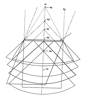
The variable vertex scan and corresponding
display format generally applies to linear or curvilinear
arrays and is a generalization of the sector scan, except
that the vertex may occur at a variable point as shown in
Fig. 5 for several different placements of variable
vertex 4a-4g. As the variable vertex approaches infinity
4f or 4g the format approaches a linear s~-Annin~ format.
As the variable vertex approaches the face of the
tr~n~=fl-lnPr at 4b, the ~ormal approaches a cector ~ormat.
The variable vertex may be in front of the tr~n~ c~r
array as at 4a and at a location not on a normal line 14
through the center of the array as at 4g.
Similarly, for curvilinear tr~nC~ Pr arrays 6
the variable vertex 4 may be located a radius behind the
~ 2036061
13
array that is greater than the radlus of ~uLv~Y~uLe 8 as
shown in Fig. 6. So, too, can the variable vertex be
placed at any location behind the array such as at 4a-4d
shown in Fig. 7.
A principal ob; ective of the described
preferred embodiment of this invention is to def ine a
scan and display format for an imaging system for which
a common vertex 4 of all acoustic scan lines can be
selectively positioned at any point within the scan
plane. As illustrated for a planar array in Flg. 8, the
variable vertex 4 is on a line normal to a line
conn-~ctln~ all tr~nRclt~ r elements of the physical
aperture or face 12 of the array at a distance y behind
the face of the array. However, the variable vertex need
not lie on this line and may be placed in front of the
physical aperture as well as behind it. The image format
which results from the location shown in Fig. 8 benefits
from an increased field o~ view at all depths and in
particular near the physical aperture.
The format applies equally well to spectral
Doppler and color flow Doppler scanning as well as to B-
mode imaging. In particular, certain mixed modes enhance
the utility of variable vertex scan and display format.
Examples include: a variable vertex scan format in 2-D
in combination with substantially parallel color flow
scan lines, shown in Fig. 17 from a remote vertex 4 ':
multiple pulsed Doppler scan lines with variable vertices
that are distinct from each other in combination with a
2-D image; or a continuous wave Doppler scan with lines
65 emanating from a variable vertex 4" positioned at the
center of the tr~nç~ r, in combination with a 2-D scan
format where the variable vertex 4 has been placed behind
the tr~n~ r face as shown in Fig. 16.
The s~-~nning method of this invention applied
Z036061
14
to a multiplexed system is illu6trated schematically in
Fig. 23. There multiplexed sub-sets of m elements, such
as 97, from the larger array 1 of n tr~nC~ r~r elements
are activated. The sub-sets 97 of active elements are
selected by a multiplexer 95 from the larger group, n,
and a system having m 1n~l~r~n~nt rh~nnel c as at 96
controls beam propagation and processes the receive
information. The multiplexer 95 may select sub-sets of
m adjacent tr Incd~lr~r elements or other groupings such as
every other one of the n elements, for example.
Included in the described: ir-nt of this
invention is the method and means to select an origin 13,
as shown in Fig. 8, and focal point 15 for a particular
ultrasound beam such that the acoustic scan line 11
appears to emanate from the common vertex 4. The actual
origin of an ultrasound beam for the planar array of Fig.
8 occurs on a line connecting the individual transducer
elements at the point CO1L--1J~ 1;11q approximately to the
center of mass of its apodization function. Equation (1)
is used to manage the apodization function such that its
center of mass is equivalent to or nearly equivalent to
the intended origin 13 of the acoustic scan line 11. The
origin 13 of the beam therefore can be controlled by
smoothly shifting this center o~ mass. The shift
required to place the beam origin 13 at or near the
intersection 13 o~ a line connecting all elements of the
tr /nc~ll]rer on the face 12 of the array with an acoustic
scan line 11 which connects the variable vertex 4 to the
focal point, as at 15, depends upon the spatial position
3 o of the variable vertex and the steering angle 0 .
By way of example, in Fig. 11 an ultrasound
beam from the planar array of Fig. 8 originates from
approximately the center of mass, Xcm of its apodization
function. The apodization function A(Xk), may be
` Z036061
described as the weighing given to the signal transmitted
from, or received rrom, an element at position Xk. The
center of mass for the apodization function iB
(1) L
~ XJ' x A (X) ' ~ (X - xk) ' dX
k=0 o
Xc~ L X
~, J A (X) ~ (X - Xk) dX
k=0 o
where ~ (x) is the Dirac delta function and has the
property that
b
J f (X) ~ (X - Xk) dX = f (XI~)
,~ .
Controlling the ultrasound beam origin is achieved by
assigning the apodization values to each element of the
physical tr In~ c~or array in such a way that the center
of mass Xcm ~uLLeD~u,lds to the acoustic scan line origin
13 . There is no requirement that Xc,,, ~ULl _ :iUU~dS to an
element position. In principle, the center of mass is
computer for each acoustic scan line 11 and a unique
apodization profile is generated for each scan linê. In
actual practice, only a limited set of profiles are
required by taking the shift invariance property of the
apodization profile into account. This means that, for
example, one can cause the center of mass to shift by
exactly one element spacing by simply shi~ting the
A~ of each apodization value from the kth
element to the (k +1) th element. This operation is easy
to accomplish by means of control logic in combination
with a miuLvl,Lu~e3sor during the quiescent period between
successive acoustic scan lines. Another unique set of
apodization profiles is required to shift the center of
- 2036061
16
mass by a fraction of an element spacing . Typically the
position of the center of mass (and therefore the
ultrasound beam origin) is controlled to within about
one-quarter of a wavelength for foci close to the
trAn~ Pr array. For a typical sector-type transducer
with half-wavelength spacing this requirement coLLa,yurlds
to two unique families of apodization profiles. All
other combinations required for each unique acoustic scan
line are obtained by simple shift operations applied to
one of these sets.
For a sector scan format as shown in Fig. 9,
the time delay which must be added to the nth element, in
order to have a focal point at range R, as at 15, along
acoustic scan line 11 from the center of the transducer
array and at angle e with respect to a reference line 14
is given as:
~ 2 ~ Tn (F1, Xn, ~ R - [R2 + X2n - 2RXn sin /~]Z } ~ T~,ff
where:
Tn = the delay required at element position Xn
to achieve a focus at range R and steering
angle e.
R = the range from the sector vertex or origin
13 to the focal point.
Xn = the position of the nth element relative
to the sector vertex or origin 13.
e = the steering angle with respect to a
reference line as shown in Fig. 9.
Toff = a variable offset added to each delay in
~ 360~
17
order to assure that the delay assigned
to each element is positive. (Negative
delay cannot be achieved).
C0 = the velocity of propagation in the body
(typically 1. 54 mm/usec) .
This equation is well-known for scctor imaging and is
c~ 8~ or example, in U.S. Patent 4,140,022.
The time delay which must be added to the nth
element in order to have a focal point at a range R'6
~rom the variable vertex 4 and at angle e with respect to
the re~erence line 14 as ,hown in Fig. 10 ~or the
variable vertex scan ~ormat is given by:
l3) _
co {( COS ~ ) [(
-2(R'o~ cOYS~) (X n yt ) ] }
where
R~e 5 the dlstance along a ray which is at an
angle e with respect to the re~erence line
14 (see Fig. lO) between the variable
vertex and the focal point.
y = the offset along a normal to the physical
array to the variable vertex.
e = the steering angle with respect to the
reference line as shown in Fig. lO.
Tloff = an arbitrary variable o~fset added to each
203606~
18
delay in order to assure that the delay
added to each element is positive.
If one con~ ors the substitutions
R' = R + Y
cos
(5)
X0 = y tan ~
then equation ( 3 ~ becomes
(6)
T'n (R; X~n - Xo, ) = C {R - [R2 + (X~n - Xo) 2 _ 2R (X~n--X") sin ol~} ~ rOIf
which has the same form as equation (2). Equation (6)
shows how to compute the delay Tln which achieves focus
lo 15 along acoustic scan line 11 at a distance R'3 from the
variable vertex 4 at an angle e from the reference line
14. The collection of individual ultrasound lines used
in a variable vertex scan formal is calculated using
equation (6~ with each acoustic scan line having unique
values for R, XO, and e . The values R, Xa and e may be
arbitrarily defined ~or each acoustic scan line.
Equation (6) disclosed how to compute the
delays for a planar array with a single fixed focal point
along a ray at an angle e with respect to a reference
line. One such set of delays (one value per element
position) is uniquely required for each acoustic scan
line. In the more general case for this invention, each
scan line originates at an arbitrary point on and at an
-
~03606~
19
arbitrary angle to the face of the array without a common
vertex. Each individual ~can line 11,11l originates at
an arbitrary intersection or point such as 13,13 ' in Fig.
21 at the face of the tr;tnC~tl~Pr array 1 and is steered
at an arbitrary angle e, e ~ with respect to a normal to
the array at its origin 13 ,13 ', respectively. As shown
in Fig. 21, an P~Pncinn of each of a ~y Lrical pair of
scan lines may pass through a common vertex such as 4,4'
for lines 11,11 ', respectively, along a normal line to
the array. Thus, the loci of the variable vertex 4,4'
for ~y LLlcal pairs of lines may lie along that normal
line rather than being a single common vertex as shown,
for example, in Fig. 8. The scan lines also may have no
common vertex at all.
Similarly, the transducer array may be any
generalized shape, such as at 90 in Fig. 22. Again, each
scan line 11,11' originates at an arbitrary point 13,13'
on the face of the array and at an angle e,e~ with
respect to a normal to the face of the array. As shown
in Fig. 22, 13,13' is the vector position of the origin
of the ultrasound lines and 91, 91 ' is the vector position
of a focal point along each line at the same or a
different range from the tr~ncflll~ Qr face. The
apodization function for each line centers more or less
about the arbitrary origin 13,13' at the face of the
array. Time delays are calculated from the vector
position of the nth element Xn, the vector position of the
ultrasound line origin 13 (k and the vector position of
the focal point for the kth ultrasound line Fk. The
eguation below, in vector notation, is comparable to
equation (6) for a fully arbitrary array and scan format
T ( X~ ) = CO ~O~-F~I - IX -F~ ¦}+ To1 f!
Z036061
For the preferred embodiment which i3
described, means to achieve dynamic focusing may be
obtained by simply generalizing er~uation (6) to include
a family of focal ranges, such as [rO, r1 ~ ~ ~ rk~ ] ~
rather than a fixed focal range, R. This constitutes a
significantly large data set. That is, the amount of
delay data required to achieve a fixed focus is given by
[Number of delay values]
= [N active trAnr rlllr r~r element] [M scan lines]
~ N M delay values
In the case o~ mirror symmetry of the scan
lines about a reference scan line, N is replaced by M/2
scan lines.
For a dynamically focused imaging system, with
R focal ranges, this becomes (K N N~ delay values.
For a high performance ultrasound imaging system with 128
active trAn~dllr~r~r elements, this amounts to approximately
3 105 delay values. As a result, means to reduce the
amount of high-speed RAN is a desired ob; ective .
Data reduction can be achieved by means of a
~9r ~ sition of the delay erluation (6) into a reference
(fixed) focus and a variable focus term. The
approximation selected for the described ~ ~ - L is
expressed as:
~7)
TAn (r, ~. Xn~ Q, ~,) 5 Tn (e ~ Xn ~ X", ~) + [ Tn (r~ Xn ~ Xo" f~r) - Tn (e ~ Xn ~ xO" ~
where: -~
~ _ , .
Tn(Q, Xn - Xv, ~) = The reference focus term
ETn (r, Xn - Xv" ~ - Tn (Q, Xn - X~ ,) ] = The Yariable focus term
- ~036061
21
(8~
Tn(r, Xn - X~ r- ¦~ 2 + (X" - X~)z - 2r(X"~ + Toft
and
r s the desired (variable) focal range, i.e.
r~yL~sel.ts one of the mem~ters of the set [rO,r1. . .rk]
Q = a reEerence (fixed) focal range
~3 = the steering angle
er= a reference angle.
It can be shown that TAn (r, ~, xn, P, ~r)
approximates Tn (r, Xn--x3, ~) to high accuracy provided
that Q is selected to be approximately midway between
the minimum and the maximum range eor r (namely between
rO and rk); and er is valid over an extent of about 25'.
That i5, a constant value of er is valid to high accuracy
for steering angles which are up to ~ 12 . 5 away from
the speci~ied reference value er. This leads to a
reduction in the data set by a factor which i5 on the
order of M O K/(M + K), which is at least an order of
magnitude .
The variable focus term, which
2 0 Tvn (r, Xn, Q, ~1~) = Tn(r- Xn - X~" ~ Tn (e' Xn - X~,, ~,)
has a very weak effect on 6teering. One can align the
origin of the variable ~ocussing term with that of the
~ixed focus term by reco~n~n~ that
~7) ( Xlt-xfl )-( Xn-x()r)=m d+~
Z03606~
22
where
d = the inter-element distance
m = some integer
= a fractional 1 ;n~lP~ < d
If ~ 0, then the delay required to generate equation
(9~ from one scan line to another (in the range of ~ for
which the refercnce angle er is valid) is generated by
simply reassigning the delay value associated with the
kth element to the (k + m) th element. Since, in general
= Or then one must have additional sets of delay
values corrP~pr~n~l;ng to the variable focus term
characterized by eguation (9). If one defines the number
of shift cases, pj such that :~ p a, and 2
is the greatest positional error which one is willing
L5 to accept, then one can rewrite equation (9) with the
variable change
tll) (Xe r ~ Xe) ~ m d ~ p a
where m and p are now control variables which are used as
indices into the delay value data tables, and m is the
O number of single element delay value data positions by
which the data must be shifted before it is applied.
This is represented schematically in Fig. 12.
The foregoing shows how the delay calculations
are generated and implemented to accommodate variable
vertex imaging for a planar transducer array. Means by
which the delay calculations are implemented to
~ ~te systems which employ heterodyning means in
combination with coarsely guantlzed delay li~es to
Z036061
23
the generation and application of transmit delay
information to the delay generator 30 by means of a
shifting of the variable focus time delays 32 followed
summing with unshifted transmit reference focus time
delays 31. This total time delay is then made available
to the transmit drivers 33 as described in U. S . patent
4, 550, 607, for example. The center of mass of the
apodization function is shifted by apodization generator
34 .
Lo Prudent apodization management requires that
the active transmit aperture, as specif ied by the
apodization function, increases about the center of mass
as the selectable transmit focus gets further from the
face of the tr~n~d~or array. This is done to maintain
a proper balance between quality of focus and depth of
focus, as rl;cr~ in U.S. Patent 4,550,607. Inevitably
as the aperture grows, it will asymmetrically reach the
end of the physical aperture. Under these conditions,
one may either truncate that portion of the apodization
function for which there is no physical aperture or
choose to maintain the apodization shape, in either case
shifting its center of mass toward the center of the
physical aperture.
When the transmit apodization l9 ' in Fig. 15
becomes end-aligned, and its center of mass is shifted
away from the desired beam origin, as at 13 ', the true
beam axis ll ' no longer aligns with the intended
ultrasound scan line 11. An important feature of the
nnin~ method of this invention is the ability to fire
an acoustic scan line 11 through the physical end of the
array. When a shallow transmit focus is selected, its
2036061.
24
aperture is large and the beam origin may be shifted far
away from its intended position 13, such as at 13 ';
however, with this large transmit aperture, the transmit
ultrasound beam i8 relatively unfocussed close to the
physical aperture where the .1; ~rl ~cl L error is
greatest. This poor focus min;mi~ the impact of the
~ plac nt errors, partiaularly if the correctly
positioned receive focus i8 strong there. Conversely,
near its focal point 17, the ultrasound beam axis and the
acoustic scan line begin to intersect, and the
.l;~rlA- L error ~l;m;n;~h~, v~n;~h;n~ completely at
the focal point. Beyond the transmit focal point 17, the
ultrasound beam axis and scan line axis again diverge,
but again, transmit defocussing m;n;m;~ the impact of
the dis~ nt errors as long as the receive focus is
correctly positioned on the ultrasound scan line 11. The
tracking of data along the scan line axis 11, and not
along the misaligned ultrasound beam axis 11 ', is
h~d through the combination of dynamic receive
apodization 18 and focussing 16.
During dynamic receive beamforming, the active
receive aperture 60, as shown in Fig. 14, grows
dynamically to 60 ' as the receive focus dynamically
becomes farther from the physical transducer along the
scan line 11 in such a manner as to keep the ratio of
focal depth to active aperture width a constant to the
greatest extent possible, as has been discussed in U. S .
Patent 4,550,607. As the receive aperture 60 grows
dyn~m;c~lly to 60' it also becomes ena-aligned, its
center of mass is also shifted away from the desired beam
origin, and the true beam axis 11 ' no longer aligns with
;~036061
switches from one focus 16 to the next 16', it accurately
tracks the information along the desired acoustic scan
line 11.
A unique set of ideal time delay data 15
calculated at the receive reference focus for all
elements and for all scan lines in a manner similar to
that done for the transmit steering time delays. These
ideal time delays can be A^~ d into coarse and fine
time delays applied at summing means 50 as described in
U.S. Patents 4,550,607 and 4,140,022.
me fine time delays may then be converted into
phase as shown, for example, in U.S. patents 4,550,607 or
4 ,140, 022 . mese delays are ~9O~ -^d into a reference
and variable focus phase and are made available to the
receiver phase generator 52 in Fig. 14 which sums the
reference, -nt phases 53 with the shifted variable
foc~lccinj c~ ^^t phases 54 to generate the composite
receiver phase values. The receiver phase values are
then used to select the phase of the mixer signals. The
active receive aperture is controlled by the receive
apodization generator 55.
~sing phased array imaging systems, it is
possible to activate, in transmit and receive, two or
more beams substantially simultAnAAllcl y from the same
aperture ? as shown in Figs. 18 and 19. Simultaneous
means that more than one pulse is in flight directed at
possibly different spatial locations at any one time
while scAnn~nj. This may be done with straight-forward
modifications to systems which have previously been
disclosed, as in, for example, U.S. Patent 4,550,607.
However, one signii~icant problem with such systems is
that multiple pulses or multiple beams along scan lines
lla, llb tend to overlap as at 70 and interfere
substantially away from the transmit focus in a planar
2036061
26
linear format, as shown in Fig. 18 and especially in the
near field, close to the tr~n~ r as shown in Fig. 19
for a typical sector scan.
One ma~ or advantage of the variable vertex
8~ ~nninJ format is the ability to separate multiple beams
much more effectively, even if ~ ,a~al ed simultaneously,
because the ultrasound scan lines lla, llb are well-
separated throughout the field of view 3 as shown in Fig.
20. Comparing Figs. 18 and 19 with Fig. 20, it is
apparent that the region of interference 70 iæ reduced or
eliminated in Fig. 20 because of the separated origins
13a,13b in the near field and because the scan lines
lla,llb diverge in the far field. The active apertures
for the two beams are ,ub~ ially less overlapping
rather than fully overlapping, as in a normal sector
scan, even though the effective aperture for each beam is
not reduced in extent. The intrinsic spatial separation
of beams (including the near field) of the variable
vertex format, in combination with dynamic apodization
and dynamic focussing, effectively optimizes performance
in multiple beam operation.