Language selection

Search

Patent 2036322 Summary

Third-party information liability

Some of the information on this Web page has been provided by external sources. The Government of Canada is not responsible for the accuracy, reliability or currency of the information supplied by external sources. Users wishing to rely upon this information should consult directly with the source of the information. Content provided by external sources is not subject to official languages, privacy and accessibility requirements.

Claims and Abstract availability

Any discrepancies in the text and image of the Claims and Abstract are due to differing posting times. Text of the Claims and Abstract are posted:

  • At the time the application is open to public inspection;
  • At the time of issue of the patent (grant).
(12) Patent: (11) CA 2036322
(54) English Title: RESILIENT FLOOR SYSTEM
(54) French Title: SYSTEME DE PLANCHER ELASTIQUE
Status: Deemed expired
Bibliographic Data
(52) Canadian Patent Classification (CPC):
  • 20/17
(51) International Patent Classification (IPC):
  • E04B 5/00 (2006.01)
  • E04F 15/18 (2006.01)
  • E04F 15/22 (2006.01)
(72) Inventors :
  • COUNIHAN, JAMES (United States of America)
(73) Owners :
  • COUNIHAN, JAMES (United States of America)
(71) Applicants :
(74) Agent: NORTON ROSE FULBRIGHT CANADA LLP/S.E.N.C.R.L., S.R.L.
(74) Associate agent:
(45) Issued: 1995-07-25
(22) Filed Date: 1991-02-14
(41) Open to Public Inspection: 1991-08-15
Examination requested: 1993-02-25
Availability of licence: N/A
(25) Language of filing: English

Patent Cooperation Treaty (PCT): No

(30) Application Priority Data:
Application No. Country/Territory Date
480,209 United States of America 1990-02-14

Abstracts

English Abstract


A resilient floor (A) is disclosed assembled on a base
surface (10) to provide a resilient floor (36) which comprises
a plurality of sub-floor sections (B) arranged generally side-
by-side. A resilient layer of material (62) is carried
generally co-extending underneath the sub-floor sections. A
slot (38,74) and widened groove (40) accommodate a fastening
member (51,71) which includes lateral flanges (58,60) and
(78,80) which limit upward movement of sub-floor sections (B).
Flooring strips (D) are nailed to the sub-floor sections so
that the flooring strips move integrally together in relative
vertical movements relative to the fastening strips (51,71).
Resilient layer (62) urges sub-floor sections (B) and integral
flooring strips (D) upwardly such that downward forces produced
by activity on the floor (36) are provided with a degree of
resiliency.


Claims

Note: Claims are shown in the official language in which they were submitted.


The embodiments of the invention in which an
exclusive property or privilege is claimed are defined
as follows:
1. A resilient flooring system for assembly on
a base surface to provide a resilient floor comprising:
a plurality of sub-floor sections arranged
generally co-extending with said floor in a side-by-
side arrangement;
a resilient layer of a resilient material
carried on said base surface underneath said sub-floor
sections;
slot means defined between adjacent floor
sections;
limit means carried in said slot means for
limiting vertical movement of said sub-floor sections;
a plurality of flooring strips extending
transverse to said sub-floor sections having an upper
floor surface defining an exterior floor; and
means for attaching said flooring strips to
said sub-floor sections so that said exterior floor and
sub-floor sections move unitarily as limited by said
limit means.

2. The system of claim 1, wherein said sub-
floor sections are elongated.

3. The system of claim 1, wherein each of said
sub-floor sections have a first edge and a second edge
opposite said first edge, and said first and second
edges each include an upwardly extending first side
terminating at an inwardly extending abutment ledge,
and said abutment ledge terminates at an upwardly
extending second side.


- 10 -


4. The system of claim 3 wherein said second side
terminates at an upper surface of said sub-floor section and
said first side originates at a base surface of said sub-floor
section.
5. The system of claim 3 wherein said limit means is
engaged by said abutment ledge to limit the upper movement of
said flooring.
6. The system of claim 5 wherein said slot means
comprises a widened groove defined between said abutment ledge
and said flooring strips in which said limit means is disposed
for relative movement.
7. The system of claim 6 wherein said limit means
comprises horizontal flange means disposed within said widened
groove which abuts said abutment ledges of said sub-floor
sections.
8. The system of claim 1 wherein said slot means
comprises a narrow slot defined between adjacent flooring
sections, and a widened groove which is widened relative to
said narrow slot, and said limit means being disposed in said
widened groove for limiting upper movement of said sub-floor
sections while permitting downward movement of said sub-floor
sections.
9. A resilient flooring system for assembly on a base
surface to provide a resilient floor comprising:
a plurality of sub-floor sections carried above
said base surface to define a sub-floor;


11


slot means formed between adjacent sub-floor
sections;
a plurality of flooring strips extending
transverse to said sub-floor sections bridging said slot means
to define a floor, and attachment means for attaching said
flooring strips to said sub-floor sections so that said floor
and sub-floor are integral and move vertically together;
fastening means disposed within said slot means
for allowing downward movement of said sub-floor sections while
limiting upward movement of said sub-floor sections relative to
said base surface; and
resilient means carried between said base surface
and said sub-floor sections biasing said sub-floor sections
upwards against said fastening means.
10. The system of claim 9 wherein said fastening means
includes a first interconnector for engaging a first sub-floor
section on a first side of said fastening means, and said
fastening means includes a second interconnector for engaging
to a second sub-floor section on a second side of said
fastening means.
11. The system of claim 9 wherein each of said sub-
floor sections have a first edge and a second edge opposite
said first edge, and said first and second edges each include
an upwardly extending first side terminating at an inwardly
extending abutment ledge, and said abutment ledge terminates at
an upwardly extending second side.


12


12. The system of claim 11 wherein said slot means
comprises a slot between said first sides of adjacent floor
sections and a widened groove between second sides of adjacent
flooring sections which is widened relative to said slot.
13. The system of claim 12 wherein said fastening
means is disposed within said widened groove and abuts said
abutment ledge.
14. The system of claim 12 wherein said fastening
means includes a generally U-shaped channel strip having a pair
of spaced vertical legs carried in said slot and first and
second lateral flanges extending in opposite directions in said
widened groove, and anchor means for anchoring said fastening
strip to said base surface.
15. The system of claim 12 wherein said fastening
means includes an elongated fastening strip having a vertical
stem carried in said slot, first and second lateral flanges
extending in opposite directions carried by said vertical stem
in said widened groove, and anchor means for anchoring said
fastening strip to said base surface.
16. The system of claim 9 wherein said slot means
includes a slot defined between first sides of adjacent
flooring sections, a widened groove defined between said second
sides of adjacent sub-floor sections, and said fastening means
is disposed within said widened groove for operatively limiting
said movement.
17. The system of claim 16 wherein said widened groove


13


tapers outwardly to reduce binding of said fastening means.
18. The system of claim 9 wherein said sub-floor co-
extends under generally the entire area of said floor.
19. The system of claim 18 wherein said resilient
means comprises a resilient layer of resilient material
generally co-extending with said sub-floor.
20. The system of claim 9 including anchor means for
anchoring said fastening strips to said base surface to
eliminate floating and dead spots in said flooring system.
21. A resilient flooring system assembled on a base
surface comprising:
a plurality of sub-floor sections carried above
said base floor sections to define a sub-floor;
slot means defined between adjacent ones of said
sub-floor sections;
an elongated fastening strip carried within said
slot means secured to said base surface;
flooring strips extending transverse to said sub-
floor sections defining a floor;
attachment means for attaching said flooring
strips to said sub-floor sections so that said sub-floor and
floor move integrally together in a vertical direction to
provide resiliency;
resilient means urging said sub-floor sections
against said fastening strips to limit the vertical upward
movement of said floor and sub-floor attached together while


14


permitting said floor and sub-floor to move downwardly against
said resilient means to provide said resilient floor.
22. The system of claim 11 wherein said slot means
includes a slot defined between first sides of adjacent
flooring sections, a widened groove defined between said second
sides of adjacent sub-floor sections.
23. The system of claim 22 wherein said fastening
strips include generally U-shaped channel strips having a pair
of spaced vertical legs carried in said slot means and first
and second lateral flanges extending in opposite directions in
said widened groove, and anchor means for anchoring said
fastening strip to said base surface.
24. The system of claim 22 wherein said fastening
strip includes a vertical stem carried in said slot, first and
second lateral flanges extending in opposite directions carried
by said vertical stem in said widened groove, and anchor means
for anchoring said fastening strip to said base surface.
25. The system of claim 21 wherein said fastening
strip comprises lateral flange means for engaging said sub-
floor sections to limit the upward movement of said sub-floor
sections.
26. The system of claim 25 wherein said sub-floor
sections include abutment means for engaging said lateral
flange means in said limiting position.
27. The system of claim 25 including a vertical
connector which carries said flange means at an upper portion


of said connector, and said vertical connector is connected to
said base surface.
28. The system of claim 25 wherein said lateral flange
means is disposed in a groove formed between adjacent sub-floor
sections.
29. The system of claim 28 wherein said groove is
defined by tapering sides which taper outwardly and upwardly to
reduce binding of said lateral flange means in said groove.
30. The system of claim 21 wherein said resilient
means comprises a resilient layer of resilient material
generally co-extending with said sub-floor.
31. The system of claim 21 wherein said sub-floor co-
extends under generally the entire area of said floor.
32. The system of claim 31 wherein said resilient
layer co-extends under generally the entire area of said floor.
33. The system of claim 3 wherein said sub-floor
sections include a first planar section, and a second planar
section affixed to said first planar section, and said second
sides are defined by beveled edges of said second planar
section.


16

Description

Note: Descriptions are shown in the official language in which they were submitted.


2036322
-


RESILIENT FLOOR SYSTEM
Background of the Invention
The invention relates for a resilient floor system for
aerobic exercise and the like.
Prior floor systems are known which provide resiliency
to an exercise or athletic floor. For example, United States
Patent No. 4,599,842 issued to the same inventor, is directed
to a fastening system which allows wood strip flooring to have
some degree of resiliency. In this system, a special fastener
is utilized which allows a flange strip to move over a portion
of its shank so that wood flooring strips secured by the flange
strip have relative movement accordingly. United States Patent
No. 4,819,932 is directed to an aerobic exercise floor system
which utilizes resilient sub-flooring and spring clips to
connect the flooring strips flexibly together. Insertion of
the spring clip requires additional construction and moving
parts susceptible to damage. This type of flooring system is
a floating flooring system which tends to float and have dead
spots. United States Patent No. 4,856,250 discloses a channel
member having a nailing bed to which flooring is nailed
transversely. The nailing bed is constrained within a "C"
shaped channel and rides on a resilient layer. The channels
are nailed to the base flooring. However, only a limited
amount of resilience is provided since the resilient layer is
of limited size and covers a limited area underneath the
flooring strips. Accordingly, an object of the invention is to
provide a simple, yet effective resilient flooring system for


-2- ~

2036322
exercise, athletics, and the like.
Another object of the invention is to provide a simple
construction for a resilient floor system wherein an outer
floor and a sub-floor move together in unison.
Another object of the invention is to provide a
resilient floor system comprising a sub-floor and transverse
flooring strips which are integrally attached yet movably
secured relative to a base surface so that the flooring strips
and sub-floor move unitarily together to provide a resilient
floor.
Summary of the Invention
A resilient flooring system for assembly on a base
surface to provide a resilient floor comprises a plurality of
sub-floor sections carried above the base surface to define a
sub-floor. Slots are formed between adjacent sub-floor
sections. A plurality of flooring strips extend transverse to
the sub-floor sections to define the resilient floor. The
flooring strips are attached to the sub-floor sections so that
the floor and sub-floor are integral and move vertically
together. Fastening strips secured to the base surface are
disposed within the slots between adjacent sub-floor sections.
The fastening strips about the sub-floor sections for allowing
downward movement of the sub-floor sections while limiting
upward movement of the sub-floor sections with the flooring
strips attached. A resilient layer is carried between the base
surface and the sub-floor sections biasing the sub-floor


2036322
_
sections upwards against the fastening strip. The sub-floor
sections have first and second opposing edges. The first and
second edges each include an upwardly extending first side
terminating at an inwardly extending abutment ledge. The
abutment ledge terminates at an upwardly extending second side.
The slots between adjacent sub-floor sections comprise a slot
between the first sides of adjacent floor sections and a
widened groove between second sides of adjacent flooring
sections widened relative to the slot. The fastening strips
include lateral flanges disposed within the widened groove and
which abut the abutment ledge. The fastening strips may
include an elongated fastening strip having a vertical stem
carried in the slot, and first and second lateral flanges
extending in opposite directions carried by the vertical stem
in the widened groove. The widened groove tapers outwardly to
reduce binding of the lateral flange of the fastening strips.
Description of the Drawings
The construction designed to carry out the invention
will hereinafter be described, together with other features
thereof.
The invention will be more readily understood from a
reading of the following specification and by reference to the
accompanying drawings forming a part thereof, wherein an
example of the invention is shown and wherein:
Figure 1 is a perspective view of a resilient floor
system according to the invention;


~036322
Figure 2 is a perspective view of a sub-floor section
constructed in accordance with the invention;
Figure 3 is an enlarged sectional view of a joint of a
resilient flooring system according to the invention; and
Figure 4 is an alternate embodiment of a resilient
joint for a resilient floor system according to the invention.
Description of a Preferred Embodiment
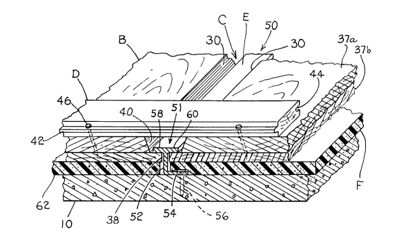
Referring now in more detail to the drawings, a
resilient flooring system, designated generally as A is
disclosed which includes a plurality of sub-floor sections B
carried above a base surface 10 to define a sub-floor 12. A
slot means C is formed between adjacent floor sections. A
plurality of flooring strips D extend transverse to the sub-
floor sections to define a floor and attach to the sub-floor
sections in an integral manner, such as by nailing. Fastening
means E is disposed within slot means C for engaging the sub-
floor sections to limit upward movement of the sub-floor
sections while allowing downward movement of the sub-floor
sections. Resilient means F in the form of a layer of
resilient material co-extends generally underneath the sub-
floor sections and resilient floor. The resilient means biases
the sub-floor sections upwardly against the fastening means.
In this manner, the floor and sub-floor are integral and move
vertically together to provide resiliency against the resilient
layer.
As can best be seen in Figure 2, sub-floor sections B

~ 2036322

include elongated wood sections 20 which have a first
edge 22 and a second edge 24. Each ledge includes a
first upwardly extending side 26, an inwardly extending
horizontal abutment ledge 28 and a second upwardly
extending side 30. Second side 30 terminates at an
upper nailing surface 32. First side 26 originates at
a base 34. Sub-floor sections B, when arranged side-
by-side as can best be seen in Figure 3, co-extend
generally underneath the entire floor 36 which is
formed by flooring strips D attached to sub-floor.
Preferably, each sub-floor section B includes a first
sheet 37a of plywood, and a second sheet 37b of
plywood, nailed or glued together. In this manner, the
sub-floor sections may be constructed on site in an
inexpensive manner. First sheet 37a may have its edges
beveled to provide second sides 30. One-half inch
plywood may be used.
Slot means C includes a narrow slot 38
defined between adjoining sub-floor sections B and a
widened groove, designated generally as 40. As can
best be seen in Figures 3 and 4, slot 38 is defined
between first sides 26 of adjoining sub-floor sections
and widened groove 40 is formed between second sides 30
of adjacent sub-floor sections. Second sides 30 taper
outwardly.
Flooring strips D include elongated,
variable length flooring strips 40 which include a
tongue 42 and a groove 44. The strips may be of
standard dimension having a width of 2 1/4 inches and a
length of from 1 foot to 8 feet. Sub-floor


,.'~

2~36322
.
sections B preferably have a width of 16 inches and a length of
4 feet. The flooring strips D extend transverse to sub-floor
sections B and bridge widened groove 40. Flooring strips D may
be affixed to sub-floor sections B by nails 46 driven into nail
surface 32 of sub-floor sections B. Fastening means E for
securing sub-floor sections B to base surface 10 and for
providing relative vertical movement of sub-floor sections
preferably includes an elongated fastening strip which includes
lateral flange means, designated generally as 50, for engaging
sub-floor sections B to limit upward movement. In Figure 3,
the elongated fastening strip is provided by a fastening strip
51 having a vertical stem 52, a base flange 54 secured to base
surface 10 by a nail 56, and first and second lateral flanges
58 and 60. Flanges 58 and 60 may extend alternately from stem
52 or may be continuous as shown. Lateral flanges 58 and 60
are abutted by abutment ledge 28 of adjacent sub-floor sections
to limit the upward movement of the sub-floor sections.
Interposed between the sub-floor sections and base surface 10
is resilient means F which urges sub-flooring sections against
the flanges. Preferably, resilient means F is a layer 62 of
resilient material, such as foam or rubber, depending on the
application. Preferably, foam layer 62 extends underneath the
sub-floor sections and abuts against stem 52. However, it is
also contemplated that foam layer 62 be continuous and that
base flange 54 sits a top and is fastened through foam layer
62. In either case, foam layer 62 is generally co-extensive


~036322

with the surface area of base 34 of all sub-floor sections B
underneath floor 36 so that a high degree of resiliency is
provided.
In Figure 4, the elongated fastening strip is provided
by a U-channel having a pair of vertical legs 70 and 72
disposed within slot 74 of slot means C. A base flange 76 is
attached to base surface 10 either directly or through foam
layer 62. In this case, lateral flange means 50 is provided by
a first flange 78 and a second flange 80 extending horizontally
from the vertical legs of the U-channel. Again, abutment ledge
28 of adjoining sub-floor sections B engages underneath the
lateral flanges 78, 80 to limit upward movement and thus
provide a means for limiting the upward movement.
As can best be seen in Figures 3 and 4, widened groove
40 (as defined by adjacent, second sides 30) tapers outwardly
so that the lateral flanges of the fastening strips do not bind
in the space, and the lateral flanges move freely, in a
relative sense, in the space, as sub-floor sections B move up
and down to provide resiliency to floor 36. Flooring strips D
are integrally attached and move with sub-floor 12 provided by
sub-floor sections B arranged generally co-extending underneath
floor 36. Resilient layer 62 extends under generally the entire
surface area of sub-floor 12 and exterior floor 36.
Thus, it can be seen that a resilient floor system can
be had for exercising, athletics, and the like, in which an
outer floor 36 is provided with a degree of resiliency as


20~6;322
_,
provided by a vertically moving sub-floor B which flexes on a
resilient layer 62 as limited by fastening strips.
While a preferred embodiment of the invention has been
described using specific terms, such description is for
illustrative purposes only, and it is to be understood that
changes and variations may be made without departing from the
spirit or scope of the following claims.


Representative Drawing
A single figure which represents the drawing illustrating the invention.
Administrative Status

For a clearer understanding of the status of the application/patent presented on this page, the site Disclaimer , as well as the definitions for Patent , Administrative Status , Maintenance Fee  and Payment History  should be consulted.

Administrative Status

Title Date
Forecasted Issue Date 1995-07-25
(22) Filed 1991-02-14
(41) Open to Public Inspection 1991-08-15
Examination Requested 1993-02-25
(45) Issued 1995-07-25
Deemed Expired 2007-02-14

Abandonment History

There is no abandonment history.

Payment History

Fee Type Anniversary Year Due Date Amount Paid Paid Date
Application Fee $0.00 1991-02-14
Maintenance Fee - Application - New Act 2 1993-02-15 $50.00 1993-02-12
Maintenance Fee - Application - New Act 3 1994-02-14 $50.00 1994-01-31
Maintenance Fee - Application - New Act 4 1995-02-14 $50.00 1995-02-13
Maintenance Fee - Patent - New Act 5 1996-02-14 $75.00 1996-02-09
Maintenance Fee - Patent - New Act 6 1997-02-14 $75.00 1997-02-13
Maintenance Fee - Patent - New Act 7 1998-02-16 $75.00 1998-02-09
Maintenance Fee - Patent - New Act 8 1999-02-15 $75.00 1999-02-09
Maintenance Fee - Patent - New Act 9 2000-02-14 $75.00 2000-02-10
Maintenance Fee - Patent - New Act 10 2001-02-14 $100.00 2001-02-07
Maintenance Fee - Patent - New Act 11 2002-02-14 $100.00 2002-01-30
Maintenance Fee - Patent - New Act 12 2003-02-14 $100.00 2003-02-11
Maintenance Fee - Patent - New Act 13 2004-02-16 $125.00 2004-02-16
Maintenance Fee - Patent - New Act 14 2005-02-14 $125.00 2004-12-14
Owners on Record

Note: Records showing the ownership history in alphabetical order.

Current Owners on Record
COUNIHAN, JAMES
Past Owners on Record
None
Past Owners that do not appear in the "Owners on Record" listing will appear in other documentation within the application.
Documents

To view selected files, please enter reCAPTCHA code :


To view images, click a link in the Document Description column. To download the documents, select one or more checkboxes in the first column and then click the "Download Selected in PDF format (Zip Archive)" or the "Download Selected as Single PDF" button.

List of published and non-published patent-specific documents on the CPD .

If you have any difficulty accessing content, you can call the Client Service Centre at 1-866-997-1936 or send them an e-mail at CIPO Client Service Centre.


Document
Description 
Date
(yyyy-mm-dd) 
Number of pages   Size of Image (KB) 
Cover Page 1995-07-25 1 15
Abstract 1995-07-25 1 24
Description 1995-07-25 8 285
Claims 1995-07-25 7 238
Drawings 1995-07-25 2 89
Representative Drawing 1999-07-12 1 27
Prosecution Correspondence 1993-02-25 2 38
Office Letter 1993-04-20 1 74
PCT Correspondence 1995-05-16 1 44
Prosecution Correspondence 1995-02-09 2 42
Examiner Requisition 1994-11-17 1 50
Prosecution Correspondence 1993-09-03 2 39
Fees 1994-01-31 1 56
Fees 1997-02-13 1 62
Fees 1996-02-09 1 55
Fees 1995-02-13 1 57
Fees 1993-02-12 1 43