Note: Descriptions are shown in the official language in which they were submitted.
2~3~31
MEDICAL DIAGNOSTIC SYSTEM
: CR05S REFERENCES TO CO-PENDING APPLICATIONS
This relates to a patent application entitled
"Regent Unit" by _, U.S. Serial No. , filed
, for use with the Medical Diagnostic System of
this patent application.
BACKGROUND OF ~HE INVENTION
1. Field of the invention - The present
invention pertains to a medical system, and more
particularly, pertains to glucose medical monitoring
- ~ diagnostic system for sampling and analyzing blood or
any components of the blood for specific readings as to
qualities of the blood. one specific use of the
present invention is for sensing the accumulating of
blood glucose for diabetics. The diagnostic system is
a portable, pocket-size, battery operated, diagnostic
system including a disposable diagnostic reagent unit
and a disposable lancet.
2. Description of the Prior Art - Prior art
blood glucose devices have operated on the principle of
taking blood from an individual by a variety of
methods, such as by a separate needle or lancing
device. An individual then had to coat a separate unit
carrying chemistry with the blood, time the chemical
reaction for about 60 seconds, wipe or remove the blood
sample from the unit, and insert the blood-coated unit
into a blood glucose meter or make a visual personal
comparison against a color standard.
There are numerous blood glucose meters in the
marketplace, and most of the instruments consume
03/24/90 2
2~3~i~3 -I
physical space and are not easily pocketable. The
instruments usually have to be carried in a large
handbag, or a individual's briefcase, or left at home
such as in the bathroom or the bedroom, or on a counter
or a table.
The prior art medical apparatuses for sensing
blood glucose required that an individual have
separately available a needle or lance for extracting
blood from the individual, units carrying blood
chemistry for creating a chemical reaction with respect
to the blood glucose and changing color, and a blood
glucose meter for reading the change in color
indicating the blood glucose level. The level of blood
glucose, when measured by a glucometer, is read from a
unit carrying the blood chemistry through the well
known process of reflectometers based on the principle
of glucose oxidation.
Some of the monitor/reagent unit systems that are
now available on the market have multiple sequential
steps that the patient must follow at exact time
intervals. Each step is subject to error by the
patient. As in most monitors, it is the patient's
- responsibility to periodically calibrate the monitor
against known color standards; validate the efficacy of
the reagent units and technique by immersing the units
in a control solution of known glucose content; and,
then comparing the color change visually against the
color standard or by using a calibrated monitor. These
types of prior art systems are subject of course to
: ~ 30 human error.
~ . .
03/24/90 3
3 1
The procedure for obtaining accurate results from
the time a drop of blood is placed on a reagent unit
pad to the time the pad color change may be read in the
glucose monitor is as now described. The patient must
stick himself/herself with a lancet. A drop of blood
must be squeezed to the surface of thP skin. The
blood must then be carefully placed on the reagent pad,
- making sure to cover the pad completely and that the
pad is never touched by the finger of the patient to
prevent contamination. Once the sample has been
applied to the surface of the reagent pad, the patient
must press a timer on the monitor. At the ~nd of the
timing, the patient must wipe, blot or wash the unit
off, using a careful technique. And for most units,
the patient must place the reacted reagent unit into
the monitor, and press a test button or closa a hatch
to obtain results. Prior art commercially available
comparable reagent units or monitors require operator
intervention in a prescribed seguence at exact time
intervals. The prior art monitors are subject to
operator error, sequence errors, timing errors, and
technique errors.
The prior art reagent units are also subject to
contamination which may affect accuracy of measurement.
A representative patent is U.S. Patent No.
4,787,398, same assignee on this patent entitled
"Glucose Medical Monitoring System", issued on November
29, 1988.
The present invention overcomes the disadvantages
of the prior art by providing an integrated hand-held
03/24/90 4
.,~ .
~ a ~
pocketable blood glucose monitoring meter which
includes an attachable disposable lancet, reagent test
device for blood glucose. unit carrying a chemical
- . reagent chemistry, and a wick for, transporting the
blood to the blood sensing reagent, resulting in a
readout of a level of the blood glucose.
03/24/90 5
~3~3~
~UM~RY OF T~IE INVENTION
One general purpose of the present invention is a
portable, shirt-pocket-size, battery-operated
diagnostic system for use by health professionals
and/or lay patients for the detection and measurement
of certain selected chemical agents or substances for
the purpose of diagnosis and/or treatment of disease.
The system application is not restricted to use with
human beings as to the sampling of blood glucose. The
system may also be extended to veterinary medicine
animals, and can also have uses in the agricultural
field, such as measurement of glucose in grapes in the
wine industry by way of example. One such medical
application is ~or insulin dependent and non-insulin
dependent diabetics for the measurement of glucose in
serum, plasma, and/or whole blood. the particular
quantity to be measured is glucose through the
principles of either reflectance, absorption or
potentiometric measurement by electronic circuitry
although other quantities can be measured.
Another purpose of the present invention is .to
provide a hand-held pocketable medical measurement
system including the engaging of a disposable lancet
and a disposable diagnostic reagent unit carrying the
blood sensing reagent for sensing readings of the
blood, such as blood glucose level. The medical system
is cost effective and simple to operate by an
individual. ~he reading, such as an individual's
- glucose level, is displayed on an LCD display on the
side of a housing of the medical system which
03/2 4/9 0 6
.
21~3~ 31
approximates th~ size of an ordinary page highlighter
which can be carried in an individual's shirt pocket.
The disposable diagnostic reagent units in sterile
packages and disposable lancets can be carried in a
corresponding packets. The housing structure
resembling a page highlighter contains the hand-held
pocketable medical system. A like housing structure
resembling a highlighter carriers the extra supply of
disposable units. The design of the present invention
provides for the utmost peace of mind for the
individual.
According to one embodiment of the present
invention, there is provided a hand-held pocketable
medical system including an electromechanical structure
for actuating a disposable lancet about a disposable
diagnostic reagent unit which engages onto the system.
The disposable diagnostic reagent unit enables a blood
sample inside a finger or on the finger surface to be
transferred to the blood reagent chemistry. The
electromechanical structure includes a spring actuated
configuration for movement of a hammer mechanism. The
disposable lancet unit and diagnostic reagent unit
engage and slide into the end o~ the hand-held
pocketable medical system, and are easily releasable
and disposable after a single use. The disposable
lancet can be reused as may be required.
- 03/24/90 7
2 ~ 3 ~
- The hand-held medical system includes a light
tight compartment with photosensing electronics
connected to a microprocessor for analyzing the
properties of the blood sensing chemistry in the
disposable diagnostic reagent unit, and for displaying
a readout and storing previous readouts. The
electronics includes verification sequences for
verifying operability of the electronics including
annunciating of a low battery condition, for verifying
the condition of a unused disposable unit, for
verifying the presence of a blood sample and for
subsequently providing multiple readings to provide for
an averaging of results. The microprocessor can be
programmed to measure other quantities.
03/24/90 8
3 ~
According to other embodiments of the present
inventionr there is provided a disposable diagnostic
reagent unit with a transporting action where a wick
serves as the transport structure for the blood. There
is als~ provided a disposable lancet unit in the hand
held medical device for the piercing of an individuals
skin.
03/24/90 9
2~3~3~
One significant aspect and feature of the present
invention is a hand-held pocketable diagnostic medical
monitoring system which is utilized for extracting a
blood sample from the body, subjecting the sample to
chemical analysis, and visually displaying the
numerical results to the individual. A disposable
diagnostic reagent unit carries the blood sensing
chemistry consisting of a reagent unit for either
delivering blood to the reagent or for causing the
reagent to be delivered to the blood. Additional
disposable units can be carried in a corresponding
structure similar to that of the medical system.
Another significant aspect and feature of the
present invention is a housing like structure which is
electromechanical, and where a button is pushed for
actuating a firing mechanism in the housing structure
against the disposable lancet contained therein through
the spring driven structure. A hammer return spring
returns the firing mechanism back to an original rest
position and at about the same time, a return spring
removes the sharp point of the lancet from the finger.
A further significant aspect and feature of the
present invention is a hand-held pocketable diagnostic
medical monitoring system which provides blood glucose
readings where the disposable diagnostic reagent unit
carries glucose-oxidase or like chemical reagent. Once
the reagent material undergoes a colorimetric,
potentiometric, or absorption action proportional to
the blood glucose concentration, the microprocessor
circuitry through the reflectance colorimeter provides
03/24/90 10
for subsequent processing of the photosensing of the
blood chemistry for displaying of the results on an LCD
display.
Another significant aspect and feature of the
present invention is a system which utilizes a slidable
disposable diagnostic reagent unit. The reagent unit
is a transport mechanism for transporting a fluid or
liquid to the reagent unit.
Still another significant aspect and feature of
the present invention is a system which inherently
through mechanical operation pushes the disposal lance
out of the housing to drop into a basket for disposal.
- 03/24/90 11
2~3~
Having thus described embodiments of the present
invention, it is principal objects hereof to provide a
pocketable diagnostic medical monitoring system,
including a disposable lancet and a disposable
diagnostic reagent unit which carries blood sensing
reagent material and which engages onto the system for
providing a subsequent readout on a visual display of
the system of a quality of the blood by the system.
The system can be broadly extended to a system for
measurement of a quantity o~ a substance in a
particular fluid or material, and is not to be
construed as strictly limited to medical applications,
as the system can be used in industry, commercial,
agricultural, consumer or even veterinary environments
as examples7
One object of the present invention is to provide
a hand-held pocketable diagnostic medical monitoring
system with a disposable lancet and a disposable
diagnostic reagent unit which engages onto the
electromechanical assembly of the medical system.
The disposable diagnostic reagent unit carries blood
sensing reagent material for sensing components of the
blood for qualities such as glucose level. Other
qualities of fluid which can be measured are
cholesterol, urea, nitrogen, hemoglobin, alcohol,
protein or other qualities of the blood with
appropriate reagent material.
Another object of the present invention is an
- electromechanical assembly which contains the
microprocessor including the software, mechanical and
03/24/90 12
3 ~
electromechanical apparatus, batteries, and related
circuitry that causes the electrical and
electromechanical functional operation. The diagnostic
is a disposable reagent unit containing the lancet for
obtaining a blood sample, typically from a person's
finger or toe, and a chemical impregnated reagent
material that reacts with the presence of blood. The
chemical reagent is sealed inside the reagent unit
housing minimizing the effects of contamination from
fingers, moisture, and light, thus improving accuracy
and precision of measurement by stabilizing the
oxidation reduction or chemical reaction of the reagent
prior to use. The sensor in the assembly detects and
measures via absorption, potentlometric, or reflectance
analysis the amount of glucose or other blood quantity
present. This analog data is provided and converted to
a digital readout display quantifying glucose in
milligrams per deciliter (mg/dl) or MMOL/L.
An additional object of the present invention is a
self-contained automatic medical monitoring system.
All operations and performance of the system are
performed automatically, mechanically and
- electronically in proper sequences. Accuracy and
precision of the measurement is enhanced because errors
due to operator interpretation, operator technique, and
timing of events, are removed from operator control
because of microprocessor based system operation and a
lot to lot as well as a test strip calibration.
Still another object of the present invention is a
medical diagnostic system which is software controlled
03/24/90 13
2~33~3~
;
and software intelligent. The system is self-
calibrating through control commands by the software,
and also based on a lot to lot material in the reagent
unit and a calibration square on the inside of the dust
cover.
03/24/90 14
~33~`~31
DESCRIPTION OF TRE PREFERRED EMBODIMEN~S
Other objects and many of the attendant advantages
of tha present invention will be readily appreciated as
the same becomes better understood by reference to the
following detailed description when considered in
connection with the accompanying drawings, in which
like reference numerals designate like parts throughout
the figures thereof and wherein:
FIG. 1 illustrates a perspective view of an
embodiment of a glucose medical monitoring system;
FIG. 2 illustrates a perspective view of the
backside of the medical diagnostic system;
FIG. 3 illustrates a perspective view of the
medical diagnostic system showing the battery case;
FIG. 4 illustrates a perspective view of the
medical diagnostic system ready to receive a disposable
lancet and a disposable diagnostic reagent strip;
FIG. 5 illustrates an exploded view in perspective
of the medical diagnostic system;
FIG. 6 illustrates an exploded view in perspective
of the optics head;
FIG. 7 illustrates an exploded view in perspective
of the firing mechanism assembly;
FIG. 8 illustrates a perspective view of the dust
cover;
FIG. 9 illustrates a perspective view of the
battery case;
FIG. 10 illustrates a side view in partial cross
section of the medical diagnostic system;
03/24/90 15
~3~3 3
FIG. ll illustrates a block diagram of the medical
diagnostic system;
FIGS. 12A, 12B and 12C illustrate an electrical
circuit schematic diagram of the medical diagnostic
system;
FIG. 13 illustrates loading of the medical
diagnostic system;
FIG. 14A - 14I illustrate component positioning
during operation of the medical diagnostic system; and
lOFIG. 15 illustrates display messages.
03/24/90 16
~3~
DESCRIPTION OF THE PREFERRED EMBODIMENTS
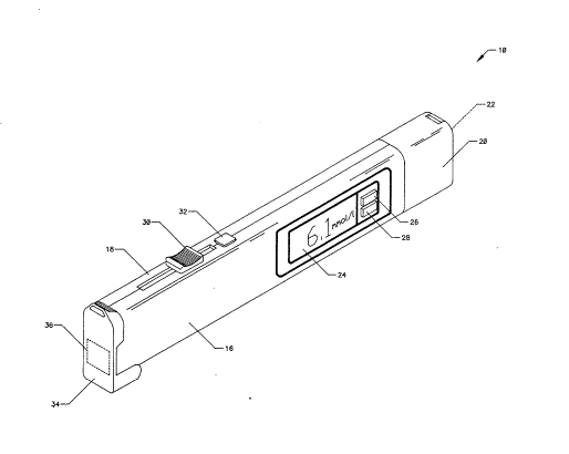
FIG. 1 illustrates a perspective view of a
portable pocketable glucose medical diagnostic system
10 including a disposable diagnostic reagent unit 12 as
illustrated and later described in particular detail in
FIG. 4. Externally visible components of the system 10
include front and back housing halves 16 and 18
respectively which enclose the electromechanical
structure as later described in detail and, a battery
case 20 and battery cover 22. An LCD or like visual
readout 24 displays the glucose levels, time, battery
condition, stored values in memory, and other mode
operational displays as later described in detail.
Conductive rubber keypad buttons 26 and 28 position
adjacent to the LCD readout 24. A actuator button 30
and a release button 32 locate on the top side of the
glucose medical monitoring system 10 for subsequent
cocXing and releasing of a firing mechanism as later
described in detail in the figures.
03/24/90 17
2~3~3~
FIG. 2 illustrates a perspective in view of the
portable pocketable glucose medical diagnostic system
10, where all numerals currespond to those elements
previously described. The flush rotatable protective
dust cover 34 includes an interior mounted color
reference calibration unit 36 and rotates on pivot
blocks 38a-38b of Fig. 8, and conforms to the front
housing 15 and the back housing 18 halves. The dust
cover 34 includes a rectangular frame 39 for the
lo accommodation of the interior mounted color reference
color calibration unit 36 as also illustrated in Fig.
8. Later members 40 and 42 extend vertically from the
interior side of the dust cover 34 and latch with the
catches 44 and 46 at the upper edges of the rear and
front housing halv~s 18 and 16 respectively. Vertical
guide bars 48 and 50 at the ends of the rear and front
housing halves 18 and 16 align along the outer surfaces
of the latches 40 and 42 to align the dust cover 34
with the ends of the combined case halves 18 and 16.
The rectangular frame 39 containing the color reference
calibration unit 36 aligns in a rectangular hole 52
between vertical end bars 54 and 56 at the ends of the
rear and front housing halves 18 and 16 respectively.
An optics window 58 aligns with the rectangular hole 52
and also with the color reference calibration unit 36
when the dust cover 34 is rotated and latched in the
closed position.
A clip 60 with a square mounting pad 62
frictionally engages a corresponding size hole 64 in
the rear housing half 18.
03/24/90 1~
~3~3~
FIG. 3 illustrates a perspective view of the
portable pocketable glucose medical diagnostic system
10, where all numerals correspond to those elements
previously described illustrated in particular is the
battery cover 22. The cover includes a back surface
22a and a side surface 22b between upper and lower
curved surfaces 22c and 22d. Upper and lower curved
surface 22c and 22d include end latch members 22e and
22f for snap engagement of the battery cover 22 within
the battery case 20. The battery cover 22 members 22a,
22b, 22c and 22d form a carriage member into which a
plurality of batteries 66a-66n are contained. The
battery cover 22 and batteries 66a-66n engage within
the battery case 20. The batteries 66a-66n are
connected as later described in detail in Fig. 5.
03/24/90 19
2~3~3~
F~G. 4 illustrates a perspective view of the
portable pocketable glucose medical diagnostic system
10 with a disposable diagnostic reagent unit 12 and a
- disposable lancet 14, where all numerals correspond to
those elements previously described. The disposable
lancet 14 is inserted into the firing mechanism
assembly 68 of Fig. 5 through an orifice 68. Orifice
68 aligns beneath the catches 44 and 46 and between the
guide 4 bars 48 and 50 and in the end of the front and
rear housings 16 and 18. After the disposable lancet
14 is inserted through the orifice 68, the disposable
diagnostic reagent unit 12 is inserted between guide
bars 48 and 50, in front of the orifice 6B and catches
44 and 46 and behind the vertical end bars 54 and 56.
The disposable reagent pad 12 includes a hole 70 and
reagent pad 72 and windows 74 and 76 for viewing of the
blood soaked reagent pad 72 by internal electronic
viewing as later described in detail. The hole 70 in
the disposable diagnostic reagent unit aligns with the
lancet needle and the windows 74 and 76 align with the
optics window 58 for electronic viewing.
03/24j90 20
2 ~
FI&. 5 illustrates an exploded view in perspective
of the portable pocketable glucose medical diagnostic
system 10, where all numerals correspond to those
elements previously described. The front housing half
16 includes a release cutout 78a a spring containment
channel 80, a release button spring 82 between the
spring containment channel 80 and the release button
32, a supported horizontally aligned firing mechanism
track member 84, a spring seat 85 between the firing
mechanism track member 84 and the top of the housing
member 16, an optics head track member 86, side spacer
bars 88 and 90, switch mounts 92a-92b and switch mount
94a-94b. A slotted cutout 96a and release cutout 78a
align along the top inner edge of the front housing
half 16 and a slotted cutout 96b and a release cutout
78b align along the top inner edge of rear housing half
18 to accommodate movement of th~ release button 32
vertically and the actuator button 30 horizontally.
The rear housing half 18 also includes mirror like
image elements of the firing mechanism track member 84
and the spring seat 85 and the optics head track member
86. The front housing half 16 also includes a piezo
sounding device mount 98, a rectangular bracket 100, a
bracket 102 for mounting of a conductive rubber keypad
104 containing buttons 26 and 28 and pivot hole 106 at
the lower end. The rear housing half 18 also includes
a pivot hole 108. Pivot holes 106 and 108 in housing
halvPs 16 and 18 accommodate the pivot blocks 38b and
38a of the dust cover 34 respectively. A clear plastic
display window 110 and the LCD panel 24 align and
03/24/gO 21
2 ~ 3 ~
secure in the rectangular brac~et 100 a foam pad 112
and an elastomeric LCD connector 114 align between the
LCD panel 24 and electronics circuit board 116. The
electronics circuit board 116 connects to an optics
head 118, a switch 120, and a switch 122 through a flex
cable 124. An optics spring retainer 126 and an optics
spring retainer 128 align behind the optics head 118 as
later illustrated. The optics head 118 aligns between
the firing mechanism track member 84 and the optics
head track member 86 on the front housing half 16 and
corresponding track members on the rear housing member
18. The firing mechanism assembly 68 aligns between
the firing mechanism track member 84 and the top
portion of the front and rear housing halves 16 and 18
and include the actuator button 30, a lancet carrier
130 a firing spring 132 and a return spring 134. A
switch actuator 13Ç aligns between the optics haad
track member 86 and the bottom of the front housing
half 16 and also between the corresponding members on
23 the rear housing half 18. A positive and negative
battery contact assembly 138 and 140 align and secure
to the battery case 20. A user label 142 aligns in a
label mount recess 144 on the rear housing half 18.
03/24/90 22
~ o ~
FIG. 6 illustrates the optics head 118 and
associated components where all numerals correspond to
those elements previously described. The assembly is
illustrated on its side for clarity of illustration.
An LED 146, an infrared LED 148 and a photo diode 150
secure within the optics head 118 with adhesive units
152 and are canted at an angle. The optics head
includes ramped surfaces 150a-150b extending from the
surface 152 of the cube like optics head 118. These
ramped surfaces 150a-150b assist in the sliding action
of the optics head 118 when tha disposable diagnostic
reagent unit 12 is inserted into the portable
pocketable glucose medical diagnostic system 10. An
optics cover 154 fits over and about the optics head
118. A thermister 156 attaches to the flex cable 124.
03/24/90 23
~3~ J~
FIG. 7 illustrates an exploded view of the firing
mechanism assembly 68 where all numerals correspond to
those elements previously described. The lancet
carrier 130 is the nucleus of this assembly and
includes a cylindrical body 158, an interior lancet
cavity 160, a longitudinal horizontally aligned slot
162 in the upper portion of the cylindrical body 158, a
vertically aligned slot 162 across the cylindrical body
158 and intersections the longitudinal horizontally
aligned slot 162, detented actuator bars 164 and 166
including rear detents 168a and 168b and forward
detents 170a and 170b. The actuator button rests atop
a hammer body 172. A hammer 174 aligns on one edge of
the hammer body 172. A cam 176 for actuation of the
switch 122 extends laterally to the side of the hammer
body 172. The hammer body 172 and hammer 174 fit in
and slide within the lancet cavity 160. A spring seat
178 in the form of a ring is molded about the
circumference of the cylindrical body 158. The firing
spring 132 fits over and about the cylindrical body
between the spring seat 178 and the hammer body 172 as
illustrated in Fig. 8. The return spring 134 seats
between the spring seat 178 and the end of the housings
16 and 18 as illustrated in Fig. 8. A planar member
180 aligns between the actuator button 30 and the
hammer body 172. At the continuous slot between the
planax member 180 and the actuator button 30 rides
along slots 96a and 96b in the case halves 16 and 18
and serves to keep the hammer aligned in the lancet
cavity 160.
03/24/90 24
FIG. 8 illustrates a perspective view of the dust
cover where all numerals correspond to those elements
previously described. Illustrated in particular is the
color reference calibration strip 36 which aligns to
the rectangular frame 39. Pivot blocks 38a and 38b are
integral to and extend inwardly from the pivot bar
members 184 and 186. Opposing pivot bar members 184
and 186 extend vertically from the main body 188 as to
the latches 40 and 42. Pivot blocXs 38a and 38b engage
pivot holes 108 and 106 respectively of Fig. 5.
03/24/90 25
J ~L
FIG. 9 illustrates a perspective view of the
battery case 20, where all numerals correspond to those
elements previously described. Positive and negative
battery contact assemblies 138 and 140 include spring
contactors 138a and 140a which frictionally engage a
plastic securing plate 190 in the end of the battery
case 20. The spring contactors 138a and 140a contact
batteries 66a - 66n which are held in the battery cover
22 of Fig~ 3. Wies 192 and 194 are electrically
connected to and extend from the battery contact
assemblies 138 and 140 and connect to the electronics
circuit board 116.
03/24/90 26
FIG. 10 illustrates a side view in partial cross
section of the medical diagnostic system 10, where all
numerals correspond to those elements previously
described. The cylindrical body 158 with the included
and internally aligned hammer body 172 align between
the top of the case, the firing mechanism track member
84, and the front position of the front and rear
housing halves 16 and 18. Firing springs 132 and
return spring 134 both seat against opposing sides of
the spring seat 178 on the cylindrical body 158. The
return spring also seats around and about the material
surrounding the orifice 68. The firing spring seats
against the spring seat 85 of the hammer body 172,
slides within the lancet cavity 160, in the cylindrical
body 158, and contacts engages and compresses the
firing spring 132, when moved to the right in this
illustration. The hammer body 172, including the cam
176 are actuated along longitudinal axis by the sliding
of the actuator button 30. As the cylindrical body 158
is positioned longitudinally the attached detented
actuator bars 164 and 166, are longitudinaily
positioned to engage or disengage detents 168a - 168b
and 170 a - 170b, upon both sides of the planar member
180, on the release button 32. A spring 82, seats in
the spring containment channel 80 and against the
interior of the release button 32 to spring the release
button 32 outwardly. The release button 32 aligns in
the release cutouts 78a and 78b also illustrated in
FIG. 5. The actuator button 30, including the planar
member 180 captures the edges of the case halves 16 and
03/24/90 27
~ ~ 3 ~
18 adjacent to slotted cutouts 98a and 96b illustrated
in FIG. 5. The cam 176 actuate the optics head switch
122 at it rear most travel. The optics head 118 aligns
along the side spacer bars 88 and 90 and the optics
head track member 86 of the front housing half 16 and
corresponding members on the rear housing half 18. A
spring alignment post 196 is included on the rear side
of the optics head and another spring alignment post
198 is included on the optics spring retainer 126. A
spring 128, aligns over the spring alignment posts 196
and 198 to slideably retain the optics head 118, in a
position to the right o~ the spring and against the
vertical end bars 56 and 54 found also in Fig. 5~ A
switch actuator bar 136 is actuated against the optics
head switch 120 as later described in detail.
03/24/90 28
2 ~
FI~. 11 illustrates and electrical block diagram
200 of the medical diagnostic system, where all numeral
correspond to those elements previously described and
as now described in Figs. 12a, 12b and 12c.
03/24/90 29
FIGS. 12A, 12B and 12C illustrate the electrical
circuit schematic package diagram 201, including the
digital display 202, clock and alarm switches 203 and
204, light emitting diodes 205 and 206, photo diode
207, strip switch 208, lance switch 209, piezo electric
beeper 210, and batteries 211 and 212. A high gain op-
amplifier 213 including, op-amp feedback capacitor 214,
- and op-amp pull-up resistor 215 are for the amplifier
circuit. A to D converter 216, inverter transistor
217 for clock for A to D converter 216, pull-up
resistor 218 for inverter 217, inverter transistor base
drive resistor 219, voltage reference regulator
integrated circuit 220, voltage reference regulator
input bypass capacitor 224, output adjustment resistor
222, output adjustment potentiometer 223, output
filter capacitor 221, voltage reference resistor 225,
and voltage reference diode 226 are for the A to D
conversion of the several colorimetric change of the
reagent and the voltage reference regulator. Switching
transistor 237 for LED 205, switching transistor 238
for LED 206, switching transistor base drive resistor
273, and switching transistor base drive resistor 274,
are for switching the LED's, LED 205 brightness
adjustment resistor 240, LED 206 brightness adjustment
resistor 239, are for compensating the LED's. RC
oscillator circuit capacitor 245, RC oscillator circuit
resistor 246, reset capacitor 243 and reset resistor
244 are for the microprocessor 249. Piezo electric
beeper impedance load resistor 232, microprocessor
pull-down resistor 241, microprocessor pull-down
03/24/90 30
2~5 ~3~
resistor 242, microprocessor pull-down resistor 247,
microprocessor pull-down resistor 248, analog power
switching transistor 271, switching transistor base
drive resistor 270, reverse voltage protector diode
272, 32.768 KHZ crystal for timer 255, timer current
limiter resistor 254, crystal oscillator capacitor 256,
and crystal oscillator capacitor 257 are for the
microprocessor 249. A to D converter 233 for
temperature variations, thermistor 273, and voltage
divider resistor 234 are for the temperature sensing
circuit. LCD bias resistors 261-264 and LCD bias
capacitors 258-260, are for LCD display 202. Serial
data output enable jack 275, serial data output jack
281, and serial data clock jack 282 are for external
connections such as to a personal computer. Bypass
capacitors 205-253, low battery and very low battery
comparators 230, and comparator voltage dividers 227-
229 are for power supply circuitry. EEPROM power
transistor 266, and EEPROM power base resistor 265,
control power to serial EEPROM 267 and 268.
The operation of the electrical circuitry of
FIGS. 12a and 12b is now described in detail. LED 205
is the light source that illuminates the reagent
chemistry area. The reagent chemistry changes color in
proportion to the amount of glucose in the blood. The
light from LED 205 reflects off the chemistry and is
sensed by photodiode 207. This signal is amplified by
a high gain op-amp 213, and then sent to the input of
the analog to digital converter 216. The analog signal
is converted to a digital signal for use by
03/24/90 31
~ 0 3 3 ~
microprocessor 249. The software algorithms in
microprocessor 249 processes this information, and then
outputs a blood glucose measurement to the liquid
crystal display 202.
LED 206 is the light source that illuminates the
lot to lot indicator on the medical diagnostic system
10. This provides information to the microprocessor
24~ to correct for variations in different lots of
chemistry. The lot to lot indicator also is used to
determine if blood has completely covered the reagent
chemistry. The reflected light ~rom LED 206 is sensed
by photodiode 207, and the signal is sent to the
microprocessor 249 in the same way as light reflected
from LED 205.
Voltage reference regulator 220, provides a
reference voltage for the medical monitoring system
circuitry. The re~erence voltage is used by the analog
to digital converter 216, the low battery detection
comparators 230, temperature A to D converter 233 and
also to keep the LED outputs constant.
Comparators 230 are used to provide a low battery
and very low battery signal to the microprocessor 249.
Switching transistor 271 is used to control the power
to the analog circuitry which is turned on only when
the photodiode 207 sensing circuits are active. A
crystal 255 provides a precision clock to the
microprocessor 249 for the various timing functions.
Switch 209 is used to initiate a blood glucose
measurement sequence by the medical monitoring system
10. Switch 208 provides the microprocessor 249 with a
03/24/90 32
~3~ '~3 1
signal to tell when a reagent unit 12 is inserted.
Switches 203 and 204 are used to set the clock and four
alarms on the medical monitoring system 10. The piezo
electric beeper 231 provides an audible beep to
indicate test progress or error conditions. Thermistor
273 with A to D converter 233 provide temperature
correction input data to microprocessor 249 to correct
for ambient temperature variations which may occur in
the user's environment. EEPROMs 267 and 268, provide
non-volatile memory storage for alarms, saved glucose
reading and various coefficients used in microprocessor
~4g, calculations.
03/24/90 33
J ,~
FIG. 13 illustrates the loading of the medical
diagnostic system 10, mode of operation with a reagent
unit 12, where all numerals cor~espond to those
alements previously described.
03/24/90 34
FIG. 14a - 14i illustrate the component
positioning and mode of electromechanical operation for
the medical diagnostic system 10, where all numerals
correspond to those elements previously described.
FIG. 14a illustrates normal position of the
elements;
FIGo 14b illustrates the actuator button pushed
into loading position;
FIG. 14c illustrates the button released and
locked in a loading position;
FIG. 14d illustrates a lancet inserted while in a
loading position;
FIG~ 14e illustrates a button pressed into a
cocked position;
FI~ 14f illustrates a strip inserted;
FIG. 14g illustrates a full extended position
during penetration;
FIG. 14h illustrates a returned to normal position
after penetration; and,
FIG. 14i illustrates the button pressed into an
ejection position for removing and e~ecting the lancet.
In operation, push the sliding button forward.
Insert the lancet into the carrier tube. Remove the
cap, press the release button. With the optic cover
25 closed, pull back the sliding button. Open the optic
cover and insert the reagent unit into position. Press
a finger firmly on the reagent unit collector. Press
the release button and squeeze the finger for hanging a
drop of blood. Place on wick in the blood bowl. Read
the glucose value displayed after 90 seconds, and
03/24/90 35
~3~
record the results. Pull out and discard the used
reagent unit. Push the sliding button forward to eject
the used lancet, and close the optic cover.
03/24/90 36
~ ~3 ~
FIG. 15 illustrates display messages generated by
algorithms in the microprocessor for display in the
LCD.
03/24/90 37
~3~
Appendix 1 illustrates a timing diagram of the
electrical components in conjunction with the
electromechanical components.
Appendix 2 is a software specification including
an EEPROM map discussing the software including the
algorithms.
Appendix 3 is the software for the microprocessor
including the algorithms.
03/24/90 38
~3~ 3
The operation of the medical diagnostic systPm
with the reagent unit, is also described in a manual
filed with the patent specification by reference as
Appendix 4.
;:
03/24/90 39
Various modifications can be made to the present
invention without departing from the apparent scope
hereof. The system can be programmed to detect these
types of changes besides color changes, as is through
the teaching of this disclosure.
WE CLAIM:
03/24/90 4