Note: Descriptions are shown in the official language in which they were submitted.
CA 02036481 1999-09-10
INTERFERENCE CANCELLATION SYSTEM HAVING
NOISE REDUCTION FEATURES AND METHOD
BACKGROUND OF THE INVENTION
Field Of The Invention
This invention relates to radio communication systems and
methods, and more particularly relates to interference
cancellation systems and methods for minimizing or eliminating
interference in radio receivers due to unwanted signals. Even
more specifically, this invention relates to a cancellation
system having noise reduction features, and a method for
reducing noise in a radio receiver system attributable to an
interference cancellation system connected to the receiver
system.
Description Of The Prior Art
Fig. 1 is a functional diagram of a conventional
interference cancellation system connected to a radio receiver
system, shown generally as including a receiver antenna 2, a
receiver 4 and a transmission line 6 interconnecting the receiver
antenna 2 and the receiver 4. The interference cancellation
system includes an auxiliary antenna 8, the purpose of which is
to receive an RF sample of an interfering signal and to provide
a reference signal. for the interference cancellation system.
-1-
CA 02036481 1999-09-10
This reference signal is used to detect the presence,
amplitude and phase of the same interfering signal in the
transmission line 6 between the receiver antenna 2 and the
receiver 4, in the following manner.
A first coupler 10 is electrically connected to the
auxiliary antenna transmission line 12 to provide a portion of
the reference signal corresponding to the interfering signal
received by the auxiliary antenna 8 to one input of a synchronous
detector 14. A sample of the signal received on the receiver
transmission line 6 is provided to a second input of the
synchronous detector 14 by using a second coupler 16 connected
to the receiver transmission line 6. The synchronous detector 14
thus compares a portion of the reference signal and the sample
signal from the receiver transmission line 6, and provides output
signals which vary in accordance with the differences and
similarities in phase and amplitude of the reference and sample
signals.
The output signals of the synchronous detector 14 are
modified by respective integrators/amplifiers 18 to provide
control signals which are provided to a signal controller 20. The
reference signal is also provided, through an appropriate
amplifier 22, to the signal controller 20. The signal controller
20 and the synchronous detector 14 thus define an adaptive
-2-
CA 02036481 1999-09-10
control loop in the interference cancellation system such that
the signal control:Ler 20, driven by the control signals, adjusts
the amplitude and phase of the reference signal and provides an
adjusted cancellation signal. The cancellation signal is then
injected into the receiver signal path defined by the receiver
antenna 2, transmission line 6 and receiver 4 with equal
amplitude but in a phase which is opposite to that of the
interference signal, thereby cancelling the interfering signal
in the receiver path. A third coupler, which is referred to as
a subtractor 24 in Fig. 1, is used to inject the cancellation
signal into the receiver signal path. The interference
cancellation system automatically and continuously maintains the
amplitude and phase of the cancellation signal for maximum
cancellation.
When the direction of the desired signal is fixed, a
directive antenna may be used for the receiver antenna. If the
direction of the interference signal is arbitrary, then an omni-
directional antenna is generally used for the auxiliary antenna
8.
In a conventional interference cancellation system, such as
the type described above and illustrated by Fig. 1 of the
drawings, the strongest signal received at the auxiliary antenna
8, be it the desired signal or the interfering signal, is
cancelled since it dominates and controls the outputs of the
synchronous detector 14. When the interfering signal arrives in
the same direction as the signal of interest, both the
interfering signal. as well as the desired signal are cancelled.
When only the desired signal is present, or when the desired
signal is stronger. than the interfering signal, the
-3-
conventional interference cancellation system must be disabled
in order to prevent cancellation of the desired signal.
Another disadvantage of the conventional cancellation
interference system is that the auxiliary antenna 8 and the
receiver antenna 2 must be spaced apart from one another so
that there is a phase difference between the reference signal
from the auxiliary antenna and the sample signal taken from the
receiver antenna. This phase difference is necessary so that
the adaptive control loop of the cancellation system, and in
the particular the synchronous detector 14 of the loop, can
distinguish between the two signals and provide a proper
detector output signal to the signal controller 20.
- 4 -
A
2036.481
Another problem with the conventional interference
cancellation system is that the interference cancellation system
is not turned off when interfering signals are absent. In such
a situation, thermal noise power from the amplifier 22 in the
auxiliary signal path of the interference cancellation system
and noise from other components of the cancellation system are
injected into the receiver signal path, even when no interfering
signals are present. This noise may degrade the performance of
the radio receiver system connected to the interference
cancellation system and effectively lower the signal-to-noise
ratio of the receiver.
- 5 -
2036481
OBJECTS AND SUMMARY OF THE INVENTION
It is an object of the present invention to provide an
interference cancellation system which will minimize noise
degradation of a radio receiver system connected to the
interference cancellation system when no interfering signals
are present.
It is another object of the present invention to provide
an interference cancellation system which will automatically
detect the relative absence of interfering signals and
disconnect itself from a radio receiver system to which it is
connected when no interfering signals are present.
It is yet another object of the present invention to
provide an interference cancellation system having noise
reduction features which is relatively simple in operation and
- 6 -
A
CA 02036481 1999-09-10
in construction.
In accordance with one form of the present invention, an
interference cancellation system for connection to a radio
receiver system having a receiver antenna, a receiver portion and
a receiver transmission line interconnecting the receiver antenna
with the receiver, includes an auxiliary antenna for receiving
an interfering signal, the auxiliary antenna providing a
reference signal corresponding to the interfering signal received
by the auxiliary antenna, and a first directional coupler coupled
to the auxiliary antenna and providing a first coupler output
signal corresponding to the reference signal. An amplifier is
coupled to the directional coupler.
The interference cancellation system further includes a
second directional coupler coupled to the receiver transmission
line. The second directional coupler provides a sample signal
corresponding to the interfering and desired signals received
by the receiver antenna.
A synchronous detector is further included in the
interference cancellation system. The synchronous detector has
at least two inputs which are respectively effectively coupled
to the first and second directional couplers so that the
synchronous detector is provided with the first coupler output
signal and the sample signal. The synchronous detector compares
the first coupler output signal and the sample signal and
provides at least one synchronous detector output signal. An
integrator/amplifier is connected to the synchronous detector to
integrate and amplify the synchronous detector output signal and
to provide a control signal.
CA 02036481 1999-09-10
The interference cancellation system further includes a
signal controller. The signal controller has a first input which
is coupled to the autput of the amplifier so that it receives an
amplified version of the reference signal, and at least a second
input which is electrically coupled to the output of the
integrator/amplifier so that it receives the control signal from
the integrator/amplifier.
The signal controller provides a cancellation signal which
corresponds to the reference signal adjusted in phase and
amplitude to cancel an interfering signal received by the radio
receiver system. This cancellation signal is injected into the
radio receiver system by a subtractor coupled to the receiver
transmission line. The cancellation signal injected into the
receiver signal path, defined by the receiver antenna,
transmission line and receiver, is equal to and opposite in
phase to the interfering signal carried by the receiver
transmission line so as to cancel the received interfering
signal.
In accordance with the present invention, the interference
cancellation system further includes a third directional coupler
which is electrically coupled to the transmission line
interconnecting the first coupler to the synchronous detector and
providing a portion of the reference signal to the synchronous
detector. An output of the third directional coupler is connected
to a detector, which is used to sense the signal power of the
reference signal. The output of the detector is provided to a
comparator.
_g_
CA 02036481 1999-09-10
The comparator compares the signal strength of that portion
of the reference signal which is provided to the detector with
a predetermined threshold level. The output of the comparator is
connected to the control input of a switch circuit, which switch
I circuit is coupled between the output of the signal controller
and the subtractor. -
When the signal power detected by the detector is below the
predetermined threshold level, the output signal of the
comparator will be in one state to cause the switch circuit to
open the signal controller path, that is, the connection between
the signal controller and the subtractor. The open switch circuit
effectively disconnects the interference cancellation system from
the radio receiver system. This prevents the injection of noise
from the cancellation system into the receiver signal path.
If the signal. power detected by the detector is above the
threshold level, the comparator's output signal will go to a
different state, causing the switch circuit to close. The signal
controller path from the signal controller to the subtractor will
then be completed, so that the signal controller can provide a
cancellation signal to the subtractor to cancel an interfering
signal carried by the receiver transmission line.
In an alternative embodiment, two switch circuits may be
used instead of the switch circuit used in the signal controller
path. One switch circuit is connected between the receiver
antenna and the subtractor, and the other switch circuit is
connected between the subtractor and the receiver. The control
input of each switch circuit is connected to the output of the
_g_
CA 02036481 1999-09-10
comparator. When the detector detects little or no signal power,
the comparator wil:L cause the two switch circuits to completely
bypass the interference cancellation system. When an interfering
signal is detected, i.e., the signal strength of the reference
signal portion detected by the detector is greater than the
predetermined threshold the comparator will change states and
cause the switch circuits to effectively reconnect the
interference cancellation system to the radio receiver system.
These and other objects, features and advantages of this
invention will be apparent from the following detailed
description of illustrative embodiments thereof, which is to be
read in connection with the accompanying drawings.
BRIEF DESCRIPTION OF. THE DRAWINGS
Fig. 1 is a functional block diagram of a conventional
interference cancellation system.
Fig. 2 is a functional block diagram of one form of the
interference cancellation system of the present invention.
Fig. 3 is a functional block diagram of a second form of
the interference cancellation system of the present invention.
Fig. 4 is a functional block diagram of a third form of
the interference cancellation system of the present invention.
Fig. 5 is a functional block diagram of a fourth form of
the interference cancellation system of the present invention.
Fig. 6 is a functional block diagram of a fifth form of
the interference cancellation system of the present invention.
-10-
CA 02036481 1999-09-10
DETAILED DESCRIPTION OF THE PREFERRED EMBODIMENTS
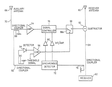
Fig. 2 illustrates functionally one form of the
interference cancellation system of the present invention. The
interference cancellation system is adapted to be connected to
a radio receiver system having a receiver antenna 60, a receiver
62, and a receiver transmission line 64 connecting the receiver
antenna 60 with the receiver 62. The receiver antenna 30 receives
an interfering signal and a desired signal, as sometimes may
occur when a receiver and a transmitter are collocated, which
signals are provided to the receiver 62 by the transmission line
64 .
The interference cancellation system includes an auxiliary
antenna 66 for receiving an interfering signal. The auxiliary
antenna 66 is connected to a first directional coupler 68 by a
transmission line 70, and provides to the first directional
coupler 68 a reference signal which corresponds to the
interfering signal received by the auxiliary antenna 66. One
output of the first directional coupler 68 is connected to an
input of a synchronous detector 72 . The other output of the f first
directional coupler 68 is provided to an amplifier 74, whose
output is connected to the input of a signal controller 76. The
first directional coupler 68 thus provides a portion of the
reference signal to the synchronous detector 72, as well as to
the signal controller 76 through the amplifier 74.
The interference cancellation system further includes a
second directional coupler 78. The second directional coupler 78
is electrically coupled to the receiver transmission line 64, and
has an output on which is provided a sample signal.
-11-
2036481.
corresponding to the signals received by the receiver antenna
60.
As mentioned previously, the interference cancellation
system includes a synchronous detector 72. The synchronous
detector 72 has at least two input ports (i.e., a reference
port and an error port) which are respectively electrically
coupled to the outputs of the first directional coupler 38 and
the second directional coupler 78 so that the reference signal
and the sample signal are provided to the two input ports of
the synchronous detector.
The synchronous detector 72 is basically a quadrature
phase detector. A typical synchronous detector which is
suitable for use is described in U.S. Patent No. 3,999,444
which issued to Rabindra Ghose and Walter Sauter. The
synchronous detector 72 compares the reference signal and the
sample signal and provides one or more detector output signals.
The synchronous detector 72 may be regarded as a switch
controlled by zero-crossing of the reference port signal of
such a detector. Because the synchronous detector is
referenced to the interference signal (i.e., the reference
signal), a non-zero sample signal will cause the synchronous
detector 72 to output a DC detector output signal. An
amplifier and/or an integrator 80 may be included in the
interference cancellation system and connected to the
synchronous detector"s output so that the DC output signals of
the detector will be amplified and integrated to create control
signals, which signals are provided to the signal controller 76
of the interference cancellation system.
- 12 -
CA 02036481 1999-09-10
A y
A signal controller 76 suitable for use in the interference
cancellation system of the present invention is described in U.S.
Patent No. 3,699,444, mentioned previously. In its simplest form,
the signal controller consists of an in-phase and a quadrature-
phase electronic attenuator, each being controllable by a
respective DC control signal. One of its inputs is provided with
a portion of the reference signal from the output of the first
directional coupler 68. Another input of the signal controller
receives the control signals from the amplifiers/integrators 80.
An output of the signal controller is provided to a subtractor
82, or 180° hybrid, which subtractor is coupled to the receiver
transmission line 64.
The signal controller 76 provides a cancellation signal to
the subtractor 82 which, in effect, injects the cancellation
signal into the receiver signal path defined by the receiver
antenna 60, transmission line 64 and receiver 62 and, more
specifically, onto the receiver transmission line carrying the
desired and interfering signals.
Because the synchronous detector 72 is referenced to t a
interfering signal to be eliminated, the non-zero sample signal
will result in DC signals at the outputs of the synchronous
detector. The DC signals are amplified and integrated to create
control signals for the signal controller 76 such that the values
of gain and phase of the cancellation signal which is generated
by the signal controller 76 change only when the sample signal
is present. As the non-zero sample signal causes the control
signals to change, the values of gain and phase of the
cancellation signal change until such values become what are
exactly required to drive the sample signal to zero. The
-13-
CA 02036481 1999-09-10
cancellation signal which is injected into the receiver
transmission line 64 is equal to and opposite in phase to the
interfering signal received by the receiver antenna 60 and
carried by the receiver transmission line 64 so as to cancel the
received interfering signal.
In one form of the present invention, the auxiliary antenna
66 is an omni-directional antenna, such as a vertical dipole.
Accordingly, the input will have a fixed gain in any direction
and thus receive an interfering signal from any direction. The
receiver antenna 60, on the other hand, is of the directive type,
such as a parabolic antenna. Accordingly, it has relatively
significant gain within a predetermined angle about its
boresight.
The receiver antenna 60 is pointed in a manner such that the
desired signal arrives within the predetermined angle. If the
gain of the interference cancellation system in the auxiliary
signal path, that is, from the auxiliary antenna 66 to the
subtractor 82, is less than the gain of the receiver antenna 60
within the predetermined angle of boresight, then the desired
signal will not be cancelled. However, all interfering signals
from directions outside of the predetermined angle will be
cancelled or reduced, as the gain of the interference
cancellation system and in particular the auxiliary signal path
of the system will exceed the gain of the receiver antenna 60
outside of the predetermined angle of boresight.
For example, assume that the gain of the receiver antenna
60 is +10 dB within the predetermined angle of boresight, and the
gain of the omni-directional auxiliary antenna 66 is zero
-14-
CA 02036481 1999-09-10
dB. The total gain of the auxiliary signal path is limited to +5
dB maximum. Any signal arriving within the 5 dB beamwidth of the
receiver antenna 60 is not cancelled since there is insufficient
signal amplitude in the auxiliary path for cancellation. This is
irrespective of whether there are any signals outside of the 5
dB beamwidth. For signals arriving outside of this beamwidth,
this limitation does not apply. Accordingly, when only the
desired signal is present (and is received within the
predetermined angle of boresight of the receiver antenna 60), it
is not cancelled.
In another form of the interference cancellation system of
the present invention, the auxiliary antenna 66 is chosen, not
to be omni-directional, but rather to exhibit a null in a fairly
narrow direction. An example of such an antenna is a loop antenna
(which has nulls in its antenna pattern which are diametrically
opposite one another) or an antenna having a cardioid pattern
(see Fig. 4). The auxiliary antenna 66 is positioned such that
the null in its antenna pattern is pointed in the direction of
the desired signal, which is also the direction in which the
receiver antenna 60 is directed, so that the centerline of the
null of the auxiliary antenna 66 is substantially parallel to the
boresight of the receiver antenna. Thus, the gain of the
auxiliary antenna 66 and, consequently, of the auxiliary signal
path from the auxiliary antenna 66 to the subtractor 82,
automatically falls off within a predetermined angle of the
boresight of the receiver antenna 60 such that no cancellation
occurs within this predetermined angle.
-15-
2p36481
Using an auxiliary antenna 66, exhibiting a null in its
antenna path allows a much higher gain to be used in the
auxiliary path, i.e., from the auxiliary antenna 66 to the
subtractor 82. The auxiliary path gain of the interference
cancellation system may, in effect, be greater than that of the
receiver antenna 60, as long as the auxiliary antenna 66 is
directed with its null towards the desired signal, and the
receiver antenna is directed in the same manner, and as long as
the gain of the auxiliary path at the null is maintained at a
level which is less than the gain of the receiver antenna
within a predetermined angle of the receiver antenna boresight.
- 16 -
203648
To minimize such noise degradation of the receiver when
no interfering signals are present, the interference
cancellation system of the present invention includes
components which either disable the interference cancellation
system from injecting noise into the receiver path when no
interfering signals are present, or automatically disconnect
the interference cancellation system from the radio receiver
when no interfering signals are present.
Referring again to Fig. 2 of the drawings, an
interference cancellation system constructed in accordance
with one form of the present invention further includes a third
directional coupler 90 electrically coupled to the transmission
line 92 interconnecting the output of the first directional
coupler 68 with the reference port of~the synchronous detector
72. This transmission line 92 carries a portion of the
reference signal corresponding to any interfering signal
received by the auxiliary antenna 66.
More specifically, the input of the third directional
coupler 90 is connected to an output of the first directional
coupler 68, and one output of the third directional coupler 90
is connected to the reference port of the synchronous detector
72. A second output of the third directional coupler 90 thus
provides an output signal which is effectively an attenuated
version of the reference signal.
The interference cancellation system further includes a
first detector 94, shown symbolically in Fig. 2 as a diode,
which is electrically coupled to the second output of the third
directional coupler 90, and which provides a detected output
- 17 -
:a
CA 02036481 1999-09-10
signal on its output in the form of a voltage which varies in
accordance'with the attenuated reference signal provided on its
input. The detector may be a rectifier demodulator, diode
detector, or the like.
The output of the detector 94 is electrically coupled to one
input of a voltage comparator 96, so as to provide the detected
output signal to the comparator. The comparator 96 includes
another input on which is provided a threshold signal in the form
of a predetermined voltage level. The output of the comparator
96 provides an output signal having two states-- one state when
the detected output signal, corresponding to the reference
signal, of the detector 94 is below the threshold signal voltage
level, and another state when the detected output signal is
greater than or equal to the threshold signal voltage level.
A switch circuit 98 basically comprising an electronic,
mechanical or other type of switch is electrically coupled to the
signal controller 76 and to the subtractor 82. More specifically,
the switch circuit 98 is positioned in the signal controller
path, that is, between the signal controller 76 and the
subtractor 82, with one terminal electrically coupled to the
output of the signal controller and another terminal electrically
coupled to the input of the subtractor, which receives the
cancellation signal from the signal controller 76. The switch
circuit 98 is depicted in Fig. 2 as including a single pole,
signal throw type switch 98a, although other configurations may
be used. The switch circuit 98 includes a control input which,
in response to the state of the comparator output signal provided
to the control input, causes the switch 98a to open or close an
-18-
CA 02036481 1999-09-10
electrical path between the terminals of the switch. The output
signal of the comparator 96 is provided to the control input of
the switch circuit 98.
When no interfering signal is present, the reference signal
will be at a relatively low power level. This reference signal
is effectively detected by the detector 94, whose detected output
signal provided to the comparator 96 will correspondingly be at
a low voltage level. If the voltage level of the detected output
signal is below the predetermined threshold signal voltage level,
the comparator 96 will cause its output signal to be in the first
state. The output signal from the comparator 96 will,
accordingly, cause the switch circuit 98 to open the electrical
path between the signal controller 76 and the subtractor 82 so
that no noise from the interference cancellation system is
injected into the receiver transmission line 64 and, in turn,
into the receiver 62.
When an interfering signal is present and received by the
auxiliary antenna 66, that portion of the reference signal on the
second output of the third directional coupler 60 and detected
by the first detector 94 will, correspondingly, cause the
detected output signal from the detector to be at a voltage level
which is greater than or equal to the predetermined threshold
signal voltage level on the second input of the comparator 96.
This will cause the output signal from the comparator 96 to
switch to the second state which, in turn, will cause the switch
circuit 98 to provide an electrical path between the signal
controller 76 and the subtractor 82, so that the cancellation
signal from the signal controller 76 may be injected into the
receiver path to cancel ariy interfering signals received by the
-19-
CA 02036481 1999-09-10
receiver antenna 60.
A modification of the interference cancellation system
described above is shown in Fig. 3 of the drawings. The
interference cancellation system includes all of the basic
components described previously and shown in Fig. 2, except that
switch circuit 98 is eliminated and replaced by two switch
circuits 100, 102.
More specifically, switch circuit 100, which may be an RF
type switch, has one terminal which is connected to the receiver
antenna 60, and another terminal which is connected to an input
of~the subtractor 82. Switch circuit 102 may similarly be an RF
type switch, having one terminal electrically coupled to the
output of the subtractor 82 and an other terminal electrically
coupled to the receiver 62.
Each switch circuit 70, 72 is depicted in Fig. 3 as
including a double pole, single throw type switch 100a,102a,
respectively. The terminal designated "3" in Fig. 3 of each
switch circuit 100,102 is connected to the wiper or switching
element of the switch 100a, 102a and, depending on the state of
the switch circuit is electrically coupled to one of two other
terminals of the switch, designated "1" and "2", respectively.
Switch circuit: 100 has its switch terminal "3" electrically
coupled to the receiver antenna 60. Its switch terminal "1" is
electrically coupled to an input of the subtractor 82.
Switch circuits 102 has its switch terminal "3" electrically
coupled to the receiver 62, and has its switch terminal "1"
electrically coupled to the output of the subtractor 82. Switch
terminals "2" of switch circuits 100, 102 are electrically
-20-
CA 02036481 1999-09-10
coupled together by a bypass transmission line 104.
Switch circuits 100, 102 each also include a control input.
As with the switch circuit 98 shown in Fig. 2, the control inputs
of switch circuits 100, 102 are electrically coupled to the
output of comparator 96. Accordingly, when the output signal from
the comparator 96 :is in the first state, corresponding to when
no interfering signal is received by the auxiliary antenna 66,
switch circuits 100, 102 will switch in response to the
comparator output signal to provide an electrical path between
the switch terminals designated "2" and "3" in Fig. 3, so-that
the receiver antenna 60 is directly electrically connected to the
receiver 62 through the bypass transmission line~104. The
interference cancellation system is entirely bypassed and
disconnected from the radio receiver system.
When an interfering signal is received by the auxiliary
antenna 66, the output signal of the comparator 96 will change
to the second state and, in turn, will cause switch circuits 100,
102 to switch to provide an electrical path between terminals "3"
and "1". This will effectively reconnect the interference
cancellation system to the radio receiver system, so that the
interference cancellation system may inject a cancellation signal
into the receiver path to cancel any interfering signals received
by the receiver antenna 60.
Another embodiment of the interference cancellation system
constructed in accordance with the present invention is
illustrated by Fig. 4 of the drawings. In this embodiment, the
interference cancellation system includes an auxiliary antenna
-21-
CA 02036481 1999-09-10
4
66, a first directional coupler 68, an amplifier 74, a signal
controller 76, integrators/amplifiers 80, a synchronous detector
72, a second directional coupler 78 and a subtractor 82. All of
these components are interconnected in the manner described with
respect to the embadiment shown in Fig. 2. This embodiment also
includes a third directional coupler 90, a first detector 94, a
comparator 96 and a switch circuit 98, again all interconnected
as described previously with respect to the embodiment
illustrated by Fig. 2, except that the comparator's first input
is not provided with the detected output signal of the first
detector 94, but rather is provided with a signal which varies
in accordance with the ratio of the power of the signal received
by the receiver antenna 60 and the power of any interfering
signal received by the auxiliary antenna 76.
More specifically, a fourth directional coupler 106 is
positioned in the receiver signal path. That is, it is interposed
between the receiver antenna 60 and the subtractor 82. Even more
specifically, a first input of the fourth directional coupler 106
is electrically coupled to the receiver antenna 60. One output
of the fourth directional coupler,106 is electrically coupled to
an input of the subtractor 82. Another output of the fourth
directional coupler is, accordingly, provided with an output
signal which is a sample of the signal received by the receiver
antenna 60.
The output signal of the fourth directional coupler 106 is
provided to the input of a second detector 108, whose output is
electrically coupled to one input of a divider 109. Another input
of divider 109 is electrically coupled to the output of the first
-22-
CA 02036481 1999-09-10
detector 94. Thus, the detected output signals of the first and
second detectors 94, 108 are provided to the inputs of the
divider 109.
Divider 109 effects a division between the detected output
signals of the first and second detectors 94, 108, with the first
detector's output signal as the denominator and the second
detector's output signal as the numerator. Since the detected
output signals of the first and second detectors vary in
accordance with the power of the signals received by the
auxiliary and receiver antennas, respectively, the divider 109
effectively provides an output signal which is the ratio of the
signal power, Pr, at the receiver antenna 60 to the signal power,
Pa, at the auxiliary antenna 66.
The divider output signal is provided to one input of the
comparator 96, whose other input is provided with a predetermined
threshold signal, as in the previous embodiments. The output
signal of the comparator 96 is provided to the control input of
switch circuit 98.
The auxiliary antenna 66 of the interference cancellation
system described above and illustrated by Fig. 4 is preferably
selected to exhibit a null in its antenna pattern, such as
provided by a loop antenna. The auxiliary antenna 66 is
positioned such that its null is pointed toward the direction of
the signal of interest (i.e., the desired signal). The receiver
antenna 60 is a directional antenna, such as a parabolic antenna.
The interference cancellation system of Fig. 4 effectively
compares the signal power in the receiver signal path (i.e.,
received by the receiver antenna) and the signal power in the
-23-
CA 02036481 1999-09-10
.s
auxiliary signal path (i.e., received by the auxiliary antenna)
of the interference cancellation system to determine if a
significant interfering signal is present at angles away from the
direction of the desired signal. If no interference is present
at angles other than the direction of the signal of interest,
then the ratio of power levels in the receiver signal path and
the auxiliary signal path is relatively high.
For example, if the gain of the receiver antenna 60 is +10
dBi, and the null of the auxiliary antenna 66 is -20 dBi, then
the ratio of the power, Pr, at the receiver antenna 60, to the
power, Pa, at the auxiliary antenna 66, is given by the equation:
Pr/Pa = 30 dB
This is because no interfering signal is received, and only
the desired signal is received within a predetermined angle of
the boresight of the receiver antenna 60 and within the null of
the auxiliary antenna 66.
If an interfering signal arrives at any angle outside of the
predetermined angle of boresight of the receiver antenna 60, this
ratio is reduced. The comparator 66 effectively compares the
ratio of the recei~aer and auxiliary antenna signal power levels
with the predetermined threshold signal voltage level. If an
interfering signal is present and the ratio is reduced such that
the divider output signal level is less than the predetermined
threshold signal level, the output signal of the comparator 96
will go to the second state, causing the switch circuit 68 to
provide an electrical path between the output of the signal
CA 02036481 1999-09-10
controller 76 and the subtractor 82, thus enabling the
interference cancellation system and allowing the system to
inject a cancellation signal into the receiver path to cancel an
interfering signal received by the receiver antenna 60.
If no interfering signal is present, the ratio of the signal
power levels will return to the original higher ratio such that
the divider output signal level is equal to or greater than the
predetermined threshold signal level. The output signal from the
comparator will ga to the first state, which will cause the
switch circuit 98 to open the signal controller path between the
signal controller 76 and the subtractor 82, thus disabling the
interference cancellation system so that no thermal noise
generated by the interference cancellation system is injected
into the receiver signal path.
A modification of the interference cancellation system shown
in Fig. 4 is illustrated by Fig. 5. In the modified embodiment,
switch circuit 98 is omitted, and switch circuits 100, 102 are
used in the receiver signal path, and are connected to the
interference cancellation system and controlled by comparator 96
in the same manner as described in relation to the embodiment
shown in Fig. 3 of the drawings. Accordingly, if the ratio of the
receiver and auxiliary antenna signal power levels falls below
a predetermined value, comparator 96 will cause switch circuits
100, 102 to electrically couple the interference cancellation
system to the radio receiver system. If the ratio is equal to or
above the predetermined value, no substantial interfering signals
are present, and the comparator 96 will cause switch circuits
-25-
CA 02036481 1999-09-10
100, 102 to disconnect the interference cancellation system from
the radio receiver system so that the signals received by the
receiver antenna 60 are provided directly to the receiver 62 on
the bypass transmission line 104.
It should be noted that, if there is only a concern about
cancelling interfering signals of a predetermined frequency, then
a frequency converter or filter 110 may be interposed between the
input of the second detector 108 and the output of the fourth
directional coupler 106, as shown in Fig. 5. The frequency
converter or filter 110 is effectively tuned to allow signals of
the predetermined frequency to be detected and used in the
comparison with the reference signal. A similar frequency
converter or filter 112 is also positioned between the input of
the first detector 94 and the output of the third directional
coupler 90 so that the ratio of the receiver and auxiliary
antenna signal power levels is not affected.
The embodiments of the interference cancellation system
illustrated by Figs . 4 and 5 ~ are highly applicable to a situation
where an omni-directional antenna, such as a dipole antenna, is
used for the auxiliary antenna 66, and a directional antenna,
such as parabolic antenna, is used as the receiver antenna 60.
In such a case, the ratio of the signal power at the two antennas
60, 66 is, effectively, the ratio of the gains of the two
antennas. When the ratio of the signal powers is less than the
ratio of the antenna gains, it may be assumed that an interfering
signal is present other than within a predetermined angle of the
boresight of the receiver antenna 60. Under these circumstances,
the interference cancellation system is enabled.
-26-
CA 02036481 1999-09-10
For example, if the gain of the receiver antenna 60 is 10
dB, and the gain of the auxiliary antenna 66, which is an omni-
directional antenna, is 0 dB, and assuming that the receiver
antenna 60 is pointed with its boresight in the direction of the
signal of interest, then the total signal power at the auxiliary
antenna 66 is equal to the signal power attributable to an
interfering signal and the signal power attributable to the
signal of interest.
If an interfering signal is within the 10 dB beamwidth of
the receiver antenna 60, then the total power at the receiver
antenna will be greater than or equal to the signal power
attributable to the interfering signal and ten times the signal
power attributable to the signal of interest.
If the signal power from the receiver antenna 60 is
approximately equal to ten times the signal power from the
auxiliary antenna 66, then there are no interfering signals of
any significance present away from the boresight of the receiver
antenna 60.
However, if the signal power from the receiver antenna 60
is now; for example, only five or seven times the signal power
from the auxiliary antenna 66, this is an indication that there
is an interfering signal of significance away from the boresight
of the receiver antenna 60. Under such conditions, the
interference cancellation system will automatically reconnect
itself to the radio receiver system.
Another embodiment of the interference cancellation system
of the present invention is illustrated by Fig. 6 of the
drawings. The interference cancellation system includes all of
the components shown in Fig. 2 of the drawings, including an
-27-
CA 02036481 1999-09-10
auxiliary antenna 66, a first directional coupler 68 an amplifier
74, a signal controller 76, a switch circuit 98 (or in the
alternative, switch circuits 100, 102 connected as shown in Fig.
3), a second directional coupler 78, a synchronous detector 72,
integrators/amplifiers 80, and a subtractor 82, all
interconnected in the manner described with respect to the
interference cancellation system shown in Fig. 2. Comparator 96
is also included. The first detector 94 and the third directional
coupler 90 are omitted in this embodiment.
In addition, the interference cancellation system includes
a fourth directional coupler 106 and a second detector 108
interconnected to the other components as described with
respect to the embodiment illustrated by Fig. 4. The output
of the second detector 108 is connected to one input of
comparator 96, and the other input of comparator 96 is provided
with a predetermined threshold signal voltage level.
The interference cancellation system of this particular
embodiment has an omni-directional auxiliary antenna 66, and an
omni-directional receiver antenna 60. This interference
cancellation system would be adapted for implementation in an
aircraft or in other situations where the direction of the
signal of interest or the interfering signal is not known for
where the signal of interest is continually changing direction
with respect to the receiver antenna.
One would generally know from the performance of the
radio receiver system what the strongest power level of the
signal of interest is, for example, -50 dBm. If the power of
the signal received by the receiver antenna 60 increases to a
level which is greater than what is expected, for example, -30
-28-
CA 02036481 1999-09-10
a
or -40 dBm, then it may be concluded that an interfering signal
is present and being received by the receiver antenna 60.
In accordance with the present invention, the fourth
directional coupler 106 samples the signal present in the
receiver signal path and received by the receiver antenna 60 and
provides the sample signal to the second detector 108. The second
detector 108 provides a detected output signal in the form of a
voltage level to one input of comparator 96. If the detector
output signal is greater than the predetermined threshold signal
voltage level provided to the other input of comparator 96,
indicating that a greater than expected signal power is received
by the receiver antenna 60, the comparator 96 will cause switch
circuit 98 to interconnect the signal controller 76 to the
subtractor 82 so that a cancellation signal may be injected into
the radio receiver system.
On the other hand, if the voltage level of the detected
output signal is less than or equal to the predetermined
threshold signal voltage level, the comparator 96 will cause
switch circuit 98 to open, effectively disconnecting the
interference cancellation system from the radio receiver system,
and so that no noise from the interference cancellation system
may be injected into the radio receiver system.
The interference cancellation system of the present
invention will minimize the noise degradation of the radio
receiver to which it is connected when no interfering signals are
present. The interference cancellation system may remain
activated, and will automatically disconnect itself from the
radio receiver when no interfering signals are detected.
-29-
CA 02036481 1999-09-10
,_
The system is simple in operation and structure, and may be
used in connection with land based or aircraft radio receiver
systems.
Although illustrative embodiments of the present invention
have been described herein with reference to the accompanying
drawings, it is to be understood that the invention is not
limited to those precise embodiments, and that various other
changes and modifications may be effected therein by one skilled
in the art without departing from the scope or spirit of the
invention.
-30-