Note: Descriptions are shown in the official language in which they were submitted.
20365~
Method related to impedance detectr)rs in r~(liosondes
5 The invention concerns a me~hod in hl~proving of the precision of impedance
detectors in radiosondes.
1~ prior art, a number of different electrically expressed temperature and
humidity detectors are known whose impedance varies as a function of the
10 quantity to be measured. Such humidity detectors are known, e.g., from the
US Patents Nos. 3,168,829 and 3,350,941 as well as from the applicant's Finnish
Patent No. 48,229.
As is known in prior art, for measurement of temperature, capacitive detectors
15 are used, which are, as a rule, based thereon that the dielectric constant of the
insulation material between the capacitor plates is dependent on the tempera-
ture, in which case the capacitance also depends on the temperature. For
example, the applicant employs very small ceramic capacitors in accordance
with said principle for temperature detectors in radiosondes. The accuracy of
such a detector is usually sufficient, because it is not heated by the measure-
ment current and because its Q-value is good. The detector is mechanically
stable, and in it no significant ageing has been noticed, and its dyn~micm is
sufficiently wide. Such a ceramic temperature detector must, however, be
protected well from moisture, e.g., by means of glass. Thereby the size of the
detector is multiplied, whereby the speed of the detector becomes lower and
the errors of radiation are increased.
Said temperature detectors can be made to operate more accurately if the
difference between their tempel d~u. e and the su~ ullding temperature is
known-m~re precisely. The present inYention provides a solution in particular
for this problem.
Y'
~'
203651Z
For its part, the FI Patent No. 48,229 is included in the prior art related to the
present invention, in which patent a capacitive humidity detector is described,
wherein the tiielectric material is a polymer film whose dielectric constant is
a function of the water amount absorbed by the polymer film.
In the detectors described above, and so also in other detectors based on
change in impedance, undesirable phenomen~ occur, which are, for example,
radiation error, slowness of detectors, and hysteresis.
In the applicant's FI Patent Application No. 58,402, a method is suggested for
reduction of undesirable properties caused by reversible alterations in an
electric humidity detector based on change in impedance, in particular in a
capacitive humidity detector in which the material sensitive to humidity is an
organic polymer and in which humidity detector the material sensitive to
humidity is heated, at least with higher relative humidities, to a temperature
higher than the temperature in the e.vi.o~...ent of the humidity detector. If
necessary, the heating capacity of the detector can be regulated as a function
of the humidity that is measured.
In said FI Patent 58,402, the temperature of the humidity detector and/or the
outside temperature is/are measured, and this or these measurement quantities
are utilized in the calculation of the humidity measurement values.
In respect of the prior art related to the present invention, reference is also
made to the applicant's FI Patent No. 57,319, in which a method is suggested
for measurement of low capacitances so that the effect of stray capacitance
is eliminated, in which method an RC oscillator circuit is used, whose output
frequency depends, preferably inversely proportionally, on the capacitance to
be measured. In the method of the latter FI patent, the capacitance to be
measured is connected between a low-impedance generator and a circuit that
measures the current only, for example b~ween~the input and the out~t of an
inverting amplifier.
20365~2
A general object of the present invention is further development of the prior-
art technology of measurement of temperature and/or humidity, in particular
in radiosonde application~.
5 An object of the present invention is further development of capacitive
temperature detectors so that their radiation error and their slowness can be
subst~nti~lly elimin~ted.
An object of the invention is to provide a novel method of measurement and
10 detector arrangement, in particular for radiosonde operation, in which the
capacitive humidity detector is subjected such a high moisture that the
detector operation is deteriorated and water or ice is collected on the surface
of the detector. When such a situation is over, it takes a long time before the
water or ice has evaporated, during which time the ~etector, of course, gives
15 an incorrect message, indicating an excessively high humidity. Under condi-
tions that gather water, a detector may give an incorrect reading, for example,
in a situation with supersaturated water vapour. By means of the heating of a
capacitive humidity detector suggested in said FI Patent 58,402, the above
drawbacks can be avoided, but, ho~ever, there remains the problem, which has
20 not been solved in prior art, that, in order that a sufficiently accurate meas-
urement of humidity could be achieved, the temperature of the detector must
be known very precisely. In order that a measurement accuracy of 1...2 % of
relative humidity could be achieved, it must be possible to measure the
temperature at a precision of about 0.1C. In the measurement of tempera-
25 ture, there may be a higher absolute error, but the difference in temperaturein relation to the environment must be known at said precision.
An object of the invention is to provide a measurement method and a detector
arrangement wherein the relative humidity can be measured at the precision of
30 1...2 % mentioned above. A further object of the invention is to provide a
measurement method and a detector arrangement which are particularly well
suitable for use in radiosondes, because, by means of the method, the detector
20365~Z
arrangement can be made simple and of low-weight construction.
An object of the invention is to provide a humidity detector by whose means it
is possible to avoid condensation of water on the surface of the humidity
5 detector, for example, when a radiosonde flies in a cloud.
In view of achieving the objectives stated above and those that will come out
later, the method of the invention is mainly characterized in that, in the
method, the temperature of the detector or detectors is measured by means of
10 a thermocouple, in which the joint of one branch of its thermoelements is
placed in connection with, or at the proximity of, the detector to be measured
and in which thermocouple the joint of the other branch is placed in the
atmosphere surrounding the detector, and that, by means of said thermocouple,
the difference between the temperature prevailing in connection with the
15 detector and the temperature in the surrounding atmosphere is detected, the
output signal of the measurement coupling of the ra(liosonde being affected by
means of an electric signal represPnting said difference in temperature, which
output signal contains the data concerning the meteorological quantity or
quantities measured by means of the detector or detectors.
In the invention, a number of advantages are achieved at the same time.
These advantages will be discussed in more detail in the following. By means
of one calibration, two temperature detectors are obtained for operation. The
other branch of the thermoelement is at some other known temperature than
25 the detector of absolute temperature proper. When a thin thermoelement wire
is used, high speed and low radiation error are achieved.
If the inverter idea applied in the invention is modified, in stead of voltages it
is also possible to measure electric currents, resistances, or other electric
30 quantities. The accuracy of measurement achieved owing to the invention is
of an order of + 0.1C, because the dyn~mi.~m is good (it is easy to measure thefrequency accurately) and because the thermocouple has no base signal, i.e. the
2036512
voltage of the therrnocouple is zero when it is not affected by a difference in
temperature.
The coupling is optimal when the difference in temperature between the
S branches of the thermocouple is;not so large that the change in frequency
produced by the thermocouple does not subst~neially exceed the co~ ,onding
frequencies of the reference capacitors.
Within the scope of the invention, it is possible to accomplish measurement of
10 humidity so that the humidity detector and the temperature detector and one
branch of the thermoelement are in good thermal contact with one another and
that this unit is heated only little. The other branch of the thermoelement is
in the open air. In such a case, condensation of water on the surface of the
humidity detector is avoided, e.g., in a sonde when it flies in a cloud. Owing
15 to the heating, the detector does, of course, not display a relative humidity of
100 %, but, since the difference in temperature is known, by means of calcula-
tion it is possible to determine the correct result of humidity measurement.
In the following, the invention will be described in detail with reference to
20 some exemplifying embodiments of the invention illustrated in the figures in
the accompanying drawing, the invention being not strictly confined to the
details of said embodiments.
Figure 1 is a block diagram illustration of the method in accordance with the
25 invention and of a detector arrangement applied in same.
Figure 2 is a central sectional view of a capacitive temperature detector in
connection with which one branch of a thermocouple is fitted.
30 Figure 3 is a top view of a capacitive humidity detector which can be applied- in the invention.
203651Z
Figure 4 is a sectional view taken along the line III-III in Fig. 3.
Figure 5 is a more detailed illustration of the measurement coupling of a
radiosonde that makes use of the method and the detector arrangement of the
5 invention.
Figure 6 is a schem~tic side view illustrating the locations of different de-
tectors on the same heated copper plate.
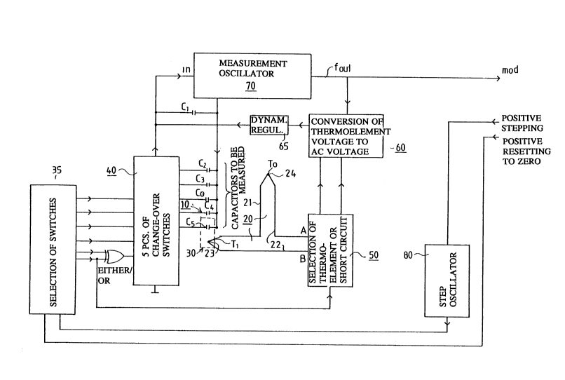
10 Fig. 1 is a s- hematic illustration, partly as a block diagram, of a wiring which
makes use of the method and the detector arrangement of the invention and
which is employed in the telemetry of radiosondes, by whose means the
pressure (P), the temperature (T) and the relative humidity (U) in the atmos-
phere surrounding the sonde are measured. As is shown in Fig. 1, in the wiring,
15 the capacitive detectors C3,C4 and C5 are used as measurement detectors. C2
is a reference capacitor, and so is the capacitor C0 connected to the switch 43.These capacitors are alternatingly cor nected to the input of the measurement
oscillator 70, to which the base capacitance C1 is co~necte~l. From the
measurement oscillator 70, the frequency Fout is obtained as the output signal.
The measurement arrangement shown in Fig. 1 includes a change-over switch
40 connected to the input side of the measurement oscillator 70, said switch 40
connecting each of the capacitances C2,C3,C4 and Cs to be measured alterna-
tingly to the input of the measurement oscillator. In respect of the details and25 the more detailed embodiment of this wiring, reference is made to the appli-
cant's FI Patent 57,319 and US Patent 4,775,830.
The change-over switches 40 of the capacitances to be measured are controlled
by means of a switch control unit 35, which receives the control signal from a
30 step oscillator 80.
, . ~ . ", ,,, . ~ ... ... . . .
X03651Z
Fig. 2 shows a temperature detector 30, whose operation is based on measure-
ment of the capacitance Cs~ The detector 30 is a ceramic capacitor in which
the dielectric constant of the insulation material has a relatively high depend-ence on temperature. The capacitance C5 to be measured is formed between
5 ; the electrode plates 33 and 34. From the electrade plates 33 and 34, conduc-tors 31 and 32 depart, which are connected in the way coming out from Figs.
1 and 5. The detector 30 is protected by means of a glass mantle 36 against
-- effects of moisture. Onto the outer face of the glass mantle 36, a copper
layer 37 has been applied, to which the joint 23 between the wires 21 and 22
10 of the thermocouple 20 has been soldered. From the copper layer 37, it is
preferable to arrange a connection to the ground through a relatively large
capacitor, e.g. a capacitor of about 10 nF. In this way, passage of the AC
voltage, used for measurement of the capacitor C5, to the thermocouple
capacitively through the glass mantle is plevented. Further, the grounding
15 capacitor prevents formation of stray capacitance in parallel with Cs along the
glass. The wire in one branch 21 of the thermocouple is, e.g., of copper (Cu),
and the wire in the other branch 22 is of Constantan (Ko). Met~ in~ of the
shield mantle of the detector 30 also prevents interfering effects of surface
leakage currents on the temperature measurement.
In the invention, it is also possible to employ a capacitive humidity detector
10, which is arranged to be heated in accordance with the principles that are
described in more detail in the applicant's FI Patent 58,402 and in Figs. 3 and
4 in the accomp~nying drawing.
The basic cons~ llction of the exemplifying embodiment of a capacitive humid-
ity detector 10 illustrated in Figs. 3 and 4 is known from the applicant's FI
Patent 48,229. The base of the detector 10 consists of a support base 11
- passive in respect of absorption of water, such as a glass plate. Onto the
30 support base 11, base contacts 12 have been made, to which the wires have
-- -been attached by means~of contacts 16, the capacitance C4 being measured
from said wires. In the detector 10, the active material is a thin polymer film
Z036~
13, onto which a thin surface contact 14 penetrable by water vapour has been
formed, which contact 14 is not in galvanic contact with any of the base
contacts 12. In this way, the capacitance C4 to be measured is formed out of
the connection in series of the capacitances formed between the base contacts
5 12 and the surface contact 14. When molecules of water-~re abs~rbed into the
film 13 material sensitive to moisture, binding of water takes place based on
two different phenomen~ One form of binding takes place on the molecular
- - - level and provides a quick and usually linear response in the form of a change
in the capacitance C4.
As the heating current of the humidity detector 10 shown in Figs. 3 and 4, it
is possible to employ the measurement ~ ent, of suitable frequency, of the
detector 10, or a heating resistor 15 may be integrated in the detector 10, the
heating current I being supplied to the contacts 17 of said resistor in the way
15 illustrated in Fig. 3. When the measurement current is used as the heating
current for the detector 10, the procedure followed may be in accordance with
the principles described in the applicant's said FI Patent 58,402.
As is shown in Figs. 3 and 4, a temperature measurement detector composed
20 of a thermocouple 20 is integrated in the detector 10 in accordance with the
same principle as in the detector 30 shown in Fig. 2. In the way in itself
known, the thermocouple 20 has thermoelement branches 21 and 22 made of
two different metals and connected with the detector 10 by means of the joint
23. One branch of the thermocouple 20 can be placed so that it measures the
25 temperature To in the atmosphere SA surrounding the sonde.
In practice, the detector constructions shown in Figs. 2,3 and 4, which have
been shown as illustrations of principle only, must also include a detector of
absolute temperature. This integrated construction is shown by Fig. 6, in which
30 the heating of the detector is also include~, because otherwise the absolute
temperature cannot be known.
- Z036Sl;~:
A detector construction 30-in accordance with Fig. 2 has been brought into
contact with a relatively thick small copper plate 41, to which a humidity
detector 42,10 has also been attached, e.g. by gluing. A heating resistor 48 is
connected to the copper plate 41. It is also preferable to connect a standard
5 capacitor C2 and a- pressure detector C3 to the plate 41, because those two
may have a depend~nce on the temperature, even though attempts are made to
make C2 as insensitive to temperature variations as possible. The same also
applies to the capacitor C3. As is shown in Fig. 6, the mantle of-the capacitor
44 (Cs) is att~ hed to the plate 41 by means of a solder joint 43. A solder
joint 51 fixes the mantle of the standard capacitor 47 (C2) to the plate 41. Thewires of the humidity detector 42 pass through holes provided in the plate 41
to the circuit card 46, to which the wires of the other components provided on
the plate 41 are also passed. This circuit card 46 is preferably made of a thin
flexible material, in which case its extension can be employed to combine said
15 unit with the rest of the electronic system.
In connection with the plate 41 shown in Fig. 6, there is a heating resistor 48,which is preferably placed so that the distance to all of the detectors and
standard capacitors is substantially equally long. In this way it is possible to20 reduce the differences in temperature between the various detectors. Out of
the same reason, it is preferable to keep the hea~ing capacity of the resistor
48 so low that the unit is not heated more than, as a rule, about 2...5C above
the temperature of the envirolllllent. In connection with the plate 41, there isa pressure detector 49 of small size, which should not be fixed by its face to
25 the copper plate 41 because of different coefficients of thermal expansion.
Therefore, the pressure detector 49 is supported on its wires only. In order
that the pressure detector 49 should, nevertheless, be at the temperature of
the plate 41, it is placed in a copper cup 50, which is fixed to the plate 41 bysoldering. In Fig 6, one joint 23 of the thermocouple 20 is seen, and the other
30 joint 24 is placed to measure the temperature To of the atmosphere SA sur-
rounding the sonde.
20365~2
In accordance with the main principle of the invention, which comes out from
Fig. 1, there is a DC voltage UO between the terminals A of the thermocouple
20, which voltage is passed through the switching unit 50 to the inverter unit
60, which convel ~ the DC voltage UO of the thermocouple 20 to an AC voltage
5 U(t). The output of the unit 60 is connected through the dynamism regulation
unit 65 to the input of the measurement oscillator 70 as is shown in Fig. 1.
In order to establish the more detailed principle of operation of the invention,the Figures 1 and 5 will be ~x~mined. The switches 61,62,63 and 64 in the unit
10 60 constitute the inverter. This inverter 60 is switched at the rate of the
output frequency fout f the measurement oscillator 70. The AC voltage
obtained is passed through a resistor of 4.7 K and through a capacitor of 100
n to the input of the measurement oscillator 70, to the same point In to which
the capacitances C2...Cs to be measured are also passed alternatingly through
15 the switches 41...45.
In Fig. 5, the dyn~mi~m regulation unit 65 shown in Fig. 1 collesponds to the
resistor R2 and to the capacitor CO. The resistor R2 convel~s the voltage
provided by the thermocouple 20 into a current which has been passed through
20 the separator capacitor CO to the input of the measurement oscillator 70, to
which the currents of the capacitors C2...C5 to be measured are also passed.
In respect of further details of the functions of the measurement oscillator 70
and of the switch units 35 and 40, reference is made to the applicant's FI
Patents 54,664 and 57,319. In Figs. 1 and 5, the capacitor C1 is a base capaci-
25 tor, with which the capacitors C2...Cs to be measured are connected in parallel.The first reference is the capacitor C2, and the second reference is the openend of the switch 43 wire, i.e. a capacitor whose capacitance is zero. In this
way, an inexpensive and definitely stable reference has been obtained.
30 The input of the inverter 60 is short-circuited by means of the change-over
switches 53-and 54. When the five capacitors C2,C3,C4,C5 and the "zero"
capacitor in the wiring system are measured, the input of the inverter 60 is
Z036S12
11
short-circuited by means of the change-over switches 53 and 54. The measure-
ment sequence further includes one measurement. This takes place so that the
switch 45 is allowed to keep the temperature measurement capacitor C5 under
measurement during one further switching cycle. At the same time, the
switches 53 and 54 remove the short circuit from the input of the inverter 60
and the switches 51 and 52 connect the thermocouple 20 to the inverter 60.
The voltage U(t) inverted from the DC voltage U0 of the thermocouple at-
tempts either to increase or- to reduce the frequency fout of the measurement
oscillator 70 depending on the polarity of the thermocouple 20. One joint 23
of the thermocouple 20 is in thermal contact with the detector 30, whereas the
joint 24 of the other branch is in the environment SA, whose temperature is To~
Thus, by means of the thermocouple 20, the temperature difference Tl-To can
be measured with very high accuracy.
The step oscillator 80 seen in Figs. 1 and 5 gives needle pulses, e.g., at inter-
vals of about 200 ms. This oscillator 80 can be controlled positively, e.g.,
during calibration. The switch selection unit 35 has a resetting to zero of its
own. The pin 5 of the circuit 35 is connected to a reset, which can also be
controlled positively. The pins 1 and 10 in the circuit IC3 of the unit 35 have
an either/or gate 36, which has the effect that the lowest change-over switch
45 remains in the measurement position during two measurement cycles (2 x
200 ms). For the time of the latter measurement cycle, the short circuit
formed by the two switches 53 and 54 in the unit 50 (IC6) is removed, and the
other two switches 51 and 52 switch on the thermoelement 20 for measure-
ment. If there is no thermocouple voltage UO between the points a and b, the
situation is the same as at short circuit and, thus, both of the measurement
cycles have the same frequency at the output of the measurement oscillator 70
(Fout)~ The either/or gates 37,66 and 67 are inverting the phase or they act as
buffers and make the rising and sinking edges of the pulses sharper.
The capacitance Cs of the detector 30 can be~calibrated at the same time as
the thermocouple 20 is calibrated. In such a case, the advantage can be
X036S12
12
obtained that, when thin thermocouple wires 21 and 22 are used, the calibration
of the temperature detector C5 proper can be made quicker, because the
thermocouple gives quickly a message as to whether there is a difference in
temperature between the reference envilon...ent SA and the detector 30.
5 Likewise, the thermocouple 20 gives a roughly correct picture of the magnitudeof this difference in temperature, and this information can be utilized when thedetector 30 is calibrated. During calibration, the free branch of the thermo-
- couple 20 should preferably be at a different temperature as compared with the
capacitor C5 and the branch connected~to it.
The current derived from the voltage UO of the thermocouple 20 by means of
the unit 50,60,65 (R2,Co) is connected to act upon the input of the measure-
ment oscillator, whereby the frequency foutl is obtained, and from the differ-
ence in frequency fout ~ fOut1 it is possible to determine, by means of calcula-
15 tion, both the difference in temperature Tl - Tû and the temperature measuredby the detector 30. It is also possible to proceed so that in the first measure-ment sequence the detectors C2,Cs are measured without the effect of the
voltage U(t) produced by the thermocouple, and in the next measurement
sequence all the capacitors C2...Cs are again measured so that, in the measure-
20 ment of Cs~ the effect of the voltage U(t) of the voltage produced by thethermocouple 20 is included. In accordance with the above, from the same
detector Cs~ two different frequencies are obtained, on whose basis it is
possible to determine both the differences in temperature T~ - To and the
absolute temperature detected on the basis of the capacitance Cs with
25 sufficiently high precision.
The difference in temperature Tl-To is represented by the difference in
frequency between the frequencies fout and foutl measured twice by means of
the detector 30. This difference in frequency is not utilized in a radiosonde.
30 It is only the computer placed on the ground in connection with a radio
receiver, which also possesses the calibration data, that calculates the correctmeteorological values from the received six modulation frequencies. These
~0365~2
frequencies can already be processed in the sonde, even up to the final data,
but the mode of processing is, neverthelPss, the same in respect of its main
principle.
5 By means of the invention, a novel method of measurement is accomplished, by
whose means a better result is obtained than by means of the prior-art ar-
rangements. The free branch of the thermoelement 20 measures the tempera-
ture To in the-sullol,llding atmosphere quickly and free from radiation error.
The other branch of the thermoelement 20 "rests" in the reference capacitor
10 Cs~ at whose temperature preferably all the other capacitors to be measured
also "rest".
The better the calibration situation corresponds to the sonrline situation, the
lower is the significance of the tempe~a~ule dependence of the invariables,
15 because the errors arising from temperature dependence are compensated for
automatically without any calculation. The errors are transferred to the
temperature dependencies in addition to their own dependencies. This is why
it is preferable that the standard capacitors are also at the proximity of the
outside temperature.
Any other capacitor whatsoever, besides C5, iS also suitable for a capacitor to
be measured twice, even a capacitor of 0 pF. The message from the thermo-
couple 20 is contained in the difference between the output frequencies fout
that is obtained when the frequency of one measurement is subtracted from the
25 frequency of the other measurement.
In the following, the patent claims will be given, and the various details of the
invention may show variation within the scope of the inventive idea defined in
said claims and differ from the details stated above for the sake of example
30 only.