Note: Descriptions are shown in the official language in which they were submitted.
r~ 2 n 3 6 5 3 ~
Title: Loader Vehicle with Operator Adjacent Boom
and Heavy Duty Elevated Rear Pivot
This invention relates to a loader vehicle, hereinafter
referred to as "of the kind specified" comprising, a body having a
front end and a rear end and provided with ground engageable
propulsion means, an operator's compartment and a boom assembly
which is pivotally mounted, at an inner end thereof, on the body,
adjacent the rear end thereof, for movement between a raised
position and a lowered position in which the boom assembly extends
forwards alongside the operator's compartment and a material
handling implement carried on an outer end of the boom assembly is
disposed forward of the front end of the body.
An object of the invention is to provide a new and
improved loader vehicle of the kind specified.
An aspect of the invention is as follows:
A loader vehicle comprising, a body having a front end
and a rear end and provided with ground engageable propulsion
means, a single operator's compartment provided at a fixed
location on the body and comprising an enclosure and a boom
assembly which is pivotally mounted, at an inner end thereof, on
the body, adjacent the rear end thereof, for movement between a
raised position and a lowered position in which the boom assembly
extends forwardly alongside the operator's compartment and a
material handling implement carried on an outer end of the boom
"
la D 2 n 3 ~ 5 3 6
assembly is disposed forward of the front end of the body wherein
the boom assembly is a unitary generally L-shaped member
comprising a lift arm assembly, which extends forwardly along one
side only of the operator's compartment, and a substantial pivot
member which is rigid with the lift arm assembly, which projects
from the inner end of the lift arm assembly on one side thereof
and extends transversely across the body from said one side of the
lift arm assembly to a position adjacent the opposite side of the
body, the pivot member being pivotally mounted on the body by
pivotal mounting means disposed at positions which are spaced
apart transversely of the body and are adjacent an upper rear end
part of the body and are on opposite sides of the body.
An access opening to the operator's compartment can
conveniently be provided on the other side of the operator's
compartment to that alongside which the lift arm assembly extends.
This is particularly convenient when the inner end of
the boom assembly is pivotally mounted on the body adjacent an
upper rear end part of the body so that, if present, a lift arm
assembly would obstruct the access opening.
2036536
If desired the pivotal mounting means may comprise a pair of discrete
mounting means or may comprise a single transversely extending elongate
mounting means.
The lift arm assembly may comprise a single member or a plurality of
members which extend(s) forwards along said one side only of the operator's
compartment.
The lift arm assembly may have an implement carrying member which
projects from the outer end of the lift arm assembly and extends transversely
of the body and has said material h~nrlline implement carried thereon.
The body may be provided with an abutment means to support the
implement carrying member against displacement in a direction rearwardly of
the vehicle when the boom assembly is in a lower position.
The abutment means may be adapted to engage a part of or carried
by the implement carrying member.
Preferably said abutment means is adapted to engage a roller rotatably
mounted on the implement carrying member.
The abutment means may comprise an abutment surface provided at
the front end of the side member disposed on the opposite side of the vehicle
to the side on which the lifting arm assembly is disposed.
Said abutment surface may have a lower, generally upright part and
an upper part which extends forwardly and upwardly.
The lift arm assembly may comprise a major rectilinearly extending
part which extends from the inner end towards the outer end and a minor
part which is inclined downwards relative to the major part and is disposed
between the major part and said implement carrying member.
Said major and minor parts may be inter-connected by an
intermediate part disposed therebetween and extending transversely inwardly
from said major part to said minor part.
The lift arm assembly, including the pivot member and the implement
carrying member may comprise a unitary component.
~ 2 0 3 6 5 ~ ~
The unitary com~ol-ent may co~ ise a tubular member which may
be of circular cross-section
The ul~ member may be made by bending from a single length of
m~teri~l
The body may co~lise a pair of ll~vGl~ely spaced side members
on which said ground engageable propulsion means are mounted.
The ground engageable propulsion means may col~lise wheels or
tracks.
The ground e-r~a~hle propulsion means may co~ lise a front wheel
~Csçmhly disposed folwardly of a rear wheel ~ccemhly~ at least one of said
wheel ~csemblies may co~lp~ise a pair of wheels spaced apart transversely of
the vehicle and at least one of said wheel ~ccemhlies being turnable about a
steering axis to permit the vehicle to be steered.
Altelnali~ely, the ground engageable L~ sporler means may colllprise
a pair of wheel ~csçmhliGs disposed on op~sile sides of the vehicle and each
pair ecmpli~ing a front wheel disposed folw~dly of a rear wheel and means
to permit the vehicle to be propelled and steered by driving the wheels on one
side of the vehicle at the same or a different speed and/or in a different
direction from those on the other side of the vehicle.
Alteruati~.ely, the ground engageable l-al~spoller means may colllplise
a pair of çndlecs tracks disposed one on one side and one on the other side
of the vehicle and means to permit the vehicle to be propelled and steered by
driving the track on one side of the vehicle at the same or a different speed
and/or a different direction from the track on the other side of the vehicle.
A portion of the opelator'~ co.np~ lent may be disposed be~- ~en
said side members.
The body may have a tl ~..C~ s;on co..~p~ llllenl at least a portion of
which is disposed between said side members and below the operator's cab
and said ll~l~s...;~ion compartment housing a lr~ cs;on to t ansll~il drive
from an engine of the vehicle to the ground engageable propulsion means.
203~536
The body may be provided with an engine compartment rearwardly
of the operator's compartment and tr~nsmi~ion compartment and said engine
compartment housing the engine of the vehicle.
The mounting means may be supported by a pair of transversely
spaced upright members disposed adjacent the rear of the body and which
extend upwardly from said side members at the rear of the operator's
compartment.
A part of said upright members may provide a part of the side walls
of the operator's cab.
A part of the side members and of the upright members may be
formed integrally with each other and the top wall of the operator's
compartment may also be integrated therewilh.
The side members may comprise loop case compartments comprising
a transversely inner wall and a tranversely outer wall joined by top and bottom
walls and end walls and a member providing one of said walls, preferably the
outer wall, may be provided integrally with the member which provides at least
part of one plate, and preferably an inner plate, of each upst~nding member.
The mounting means may be disposed on or adjacent a top rear part
of the operator's compartment at a level whereby an operator can see
ho~i~onlally rearwardly beneath the pivot member.
The boom assembly may colllplise an implement levelling linkage to
m~int~in the material h~ndling implement in a fixed orientation relative to the
body irrespective of raising and lowering of the lift arm assembly.
A pair of ground engageable propulsion means may be disposed on
opposite sides of the vehicle whereby the vehicle can be propelled and steered
by driving the propulsion means on one side of the vehicle at the same or
different speed and/or direction from that on the other side and having a
m~nll~lly operable propulsion control means to control the direction in which,
and the speed at which, the vehicle is propelled by the propulsion means and
said propulsion control means is arranged and disposed so as to be operable
by one hand of an operator.
;~036S36
s
Where the vehicle is a loader vehicle the vehicle may be provided
with a loader control means to control raising and lowering of the boom
assembly and movement of the material h~n(lling implement relative to the
boom assembly, the loader control means being arranged and disposed so as
to be operable by the other hand of the operator.
The propulsion control member may be operatively connected to said
input members by a mechanical linkage.
Alternatively the propulsion control member may be operatively
connected to said input members by a fluid pressure linkage.
Where the linkage is a fluid plessure linkage the input members may
be provided with input levers which are connected to double acting fluid
operated rams to which fluid is fed under the control of said loader control
member.
Each fluid operated ram may be pivotally mounted to the body at a
single location for pivotal movement about an axis parallel to the axis of
rotation of the associated input member.
With the fluid pressure operated linkage the propulsion control
member may co~ ise a universally mounted lever having a part spherical
valve operating surface normal to the operating lever and there being four
valve operating members engageable with said surface.
The valve operating members may be disposed at 45~ to the drive
direction of the vehicle and the propulsion control means may be provided
with resilient biasing means so as normally to seek a median position with
respect to a direction transverse to the fore and aft axis of the vehicle.
Consequently, an operator feels less resistance to movement of the control
member in a direction parellel to the fore and aft direction of the vehicle
which, in use, provides forward or reverse drive, whilst any lateral component
of movement of the propulsion control member encounters a stronger bias,
therefore m~king the vehicle easier and safer to drive.
The biasing means may colll~-ise a pair of resiliently biased plungers
adapted to engage the operating surface on opposite sides of a central axis
X036536
thereof and disposed on a line transverse to the fore and aft direction of the
vehicle.
The valve operating members may themselves be resiliently biased
into engagement with the operating surface and in this case the plungers have
a stronger resilient bias than is provided to the valve operating members.
The above described hydraulic control enables operation of the input
members from any desired locaffon in the operator's co~ al Illlent without the
need to provide a route for a mechanical linkage and the above described
single pivot of the two operating rams enables the hydraulic linkage to be
simply and coll./eniently provided.
The invention is particularly concerned with a vehicle where the input
members are the swash plate angle control members of hydl o~latic pumps, the
oul~uls of which are fed to hydrostatic motors which drive the ground
engageable propulsion means.
At least one of said input levers may be adapted to be engaged at a
first position on one side of their axes of rotation and at a second position onthe opposite side of their axis of rotation but facing in the same direction by
a centring lever which is mounted on the body adjacent one end and urged in
the direction towards the axis of pivot of the associated input lever so that said
centring lever engages said input lever at said positions when the input lever
is in a neutral position.
Preferably such a centring lever is provided for both input levers and
the centring levers are disposed so as to be urged in the direction towards the
associated axis of pivot of the associated input lever, for example, either by
positioning the centring levers on the side of their respective input lever which
is remote from the other input lever and inter-connecting the centring levers
by resilient biasing means to pivot them in opposite directions to urge them
towards their associated input lever axes, or by positioning the centring leverson the side of their associated input lever which is adjacent the other input
lever and resiliently biasing said centring levers apart.
X036536
Such an arrangement ensures that the input members are
automatically centred and is applicable for any of the linkages described
hereinbefore, i.e. the direct mechanical linkage or mechanical linkage with
integral servo mech~ni~m or fluid pressure linkage. It will be appreciated that
the centring levers apply a centring or return pres~ule to the input levers at
all times when they are displaced from their neutral position. This ensures
that the input members are returned to their neutral position in which the
ground engageable propulsion means m~int~in the vehicle stationary when no
input is provided to the propulsion control means. Accordingly, any risk of the
vehicle moving when, for example, the engine is started without an operator
in the operator's compartment is avoided.
From a second more specific aspect of the invention:
A restraint member may be mounted on the body for movement
between an operative position in which the restraint member extends
transversely of the operator's compartment in restraining relationship with the
seat and an inoperative position in which passage of an operator into and out
of the seat is permitted.
The restraint member may be carried on at least one lever which is
pivotally mounted on the body.
The operator's compartment may be obstructed from access at one
side thereof and is provided with an access opening at the other side thereof
and a control means for a first function of the vehicle is mounted at said otherside of the operator's compartment for movement between an operative
position wherein it is presented for m~nll~l engagement by an operator sitting
in said seat and an inoperative position spaced from said operative position to
permit an operator to pass through said access opening.
A control means for a second function of the vehicle may be provided
at said one side of the operator's compartment.
Said control means for the second function may be mounted on a
fixed part of the body or may be mounted for movement between an operative
~0;~65~6
position where it is presented for m~ml~l engagement by an operator sitting
in said seat and an inoperative position spaced from said operative position.
The or each control means may be mounted for movement on a
respective lever the or each of which is pivotally mounted on the body about
an axis which extends transverse to the body for movement between a
generally upright position when the respective control member is in said
operative position and a generally forward position in which said respective
control member is in said inoperative position.
The p*oted lever or levers of the invention may be arranged to
operate means to apply a parking brake when in said inoperative position, for
example, by a Bowden cable or rigid linkage and may as well or alternatively
be provided with an interlock to the engine of the vehicle to pr~vellt the
engine to be started and run.
An interlock sensitive to the presence of an operator on the seat may
be provided so that the engine can only be started when an operator is sitting
in the seat.
One of said first and second functions may comprise a propulsion
control means to control the direction in which, and the speed at which, the
vehicle is propelled, whilst the other function may collll~lise a loader controlmeans to control raising and lowering of the boom assembly for movement of
the material h~n-lling implement relative to the boom assembly.
Preferably the loader control means colll~lises said control means for
the first function of the vehicle and the propulsion control means comprises
the control means for the second function of the vehicle.
Ground engageable propulsion wheels may be disposed on opposite
sides of the body, each propulsion wheel being carried on an outer end of a
stub axle which is housed, so as to be rotatable about an axis of rotation, in
a stub axle housing member mounted on the body. An inner end of each stub
axle may have a driven wheel thereon which is driven by a flexible loop from
a driving wheel driven by a motor or the inner end of each stub axle may be
driven by other means such as a separate motor for each stub axle.
~036536
Each stub axle housing member may be provided with a carrier
member which is mountable on the body in a selected one of a plurality of
~n~ r positions about a reference axis, the stub axle housing member being
positioned relative to the carrier member so that said axis of rotation is
disposed eccentrically relative to said reference axis.
Preferably, the carrier member and the body are provided with co-
operating guide means which guide the carrier member for rotation about said
reference axis.
By virtue of said eccentric disposition of the axis of rotation, the
distance between the driven wheel and the driving wheel may be adjusted
thereby pellllillhlg adjustment of the wheel base, the ground clearance and the
height of the centre of gravity of the m~ ine; where the stub axles are driven
by a flexible loop, a flexible loop of appropliate length is provided. In
addition, a flexible loop of a given length may be tensioned.
The body may be provided with an engine, two pairs of ground
engageable propulsion wheels disposed on opposite sides of the body, a
hydraulic drive means inc~ ling first and second variable displacement pumps
driven by the engine and operatively connected to first and second hydraulic
motors disposed on opposite sides of the body, each pump being drivably
connected to two ground engageable propulsion wheels of an associated one
of said pairs of wheels on the associated side of the body by first and second
endless loops each of which is engaged with a driving wheel driven by the
pump and with a driven wheel connected to an associated one of the ground
engageable wheels of said pair and propulsion control means whereby the
hydraulic drive means can drive the pair of wheels on one side of the vehicle
at the same or a different speed and/direction from the pair of wheels on the
other side of the vehicle to propel and steer the vehicle.
The body may be provided with a longitll~lin~lly extending loop case
compartment on each side of the vehicle, each loop case collll)al Illlent havinga transversely inner wall and a transversely outer wall joined by top and
bottom walls and end walls, said stub axle housing member or members being
Z036536
mounted on the outer wall with said driven wheel or wheels disposed within
said compartment.
Preferably, two stub axle housing members are provided on each side
of the vehicle and each of said housing members are mounted on said outer
wall with said driven wheels disposed within the compartment with said driving
wheels disposed within the compartment therebetween with said loops engaged
with respective driving and driven wheels.
The outer wall may be provided with a circular opening for the or
each housing member to provide one of said co-operating guide means.
Ground engageable propulsion wheels may be disposed on opposite
sides of the body, each propulsion wheel being driven by a flexible loop from
a driving wheel driven by a motor.
The driving wheel or wheels may be carried on an output shaft of a
motor and are ul~u~Jported by means independent of the motor.
The body may be provided with a longitllclin~lly extending loop case
colll~a~ Inlent on each side of the vehicle, each loop case colll~arllllent having
a transversely inner wall and a llal~svel~ely outer wall joined by top and
bottom walls and end walls.
Each motor may be mounted on the inner or the outer wall of an
associated loop case collll~al Illlent with the driving wheel or wheels disposedwithin the associated loop case collll)al Illlent.
The driving wheel or wheels are preferably carried on an output shaft
of the associated motor and are ulLsupl)orted by the other wall of the
associated compartment.
The output shaft of each motor may be supported at an outer part
thereof by an outer bearing carried by a bracket fastened to the respective
motor body.
The bracket may be provided with openings to permit of passage of
said loop or loops.
The driving wheel or wheels may be provided on a sleeve member
which receives the output shaft of the associated motor therein at one end, an
Fi20~653 ~
11
inner bealing being provided between the sleeve and the body of the motor.
Preferably, the outer bearing is provided between the bracket and said
sleeve.
A brake memher may be carried by the output shaft oulwardly of said
sleeve.
The outer wall each loop case colllpa~ ent may be provided with an
opening adjacent to the motor and driving wheel or wheels to permit of
manipulation of a loop into driving relationship with a driving wheel and drivenwheel.
The brake member may be disposed oul..~dly of the part of the outer
wall of the loop case co...p~ llcnt at loc~tionc spaced from said motor and
a re~uovable eYtencion ho~ g may be provided to en~lose the brake member.
The or each en~lle~c loop may colllplise a chain such as a roller chain
and the driving and driven wheels may colll~lise sprockets for engagement
with the chain.
~ lte l~ ely, the or each endlecc loop may co~u~lise a toothed or
unloothed belt and the driving and driven wheels appropriate pulleys.
The body may have a ll~nsll~ ;on comr~rtment at least part of which
is de-fined by and disposed between said side members and disposed below the
operator's co...~ lent and said l~n~...;~;on col~ lllent may have a
c~ ;on to ~anslllil drive from an engine of the vehicle to the ground
engageable ~ ler means.
The body may be provided with an engine colll~)aullllent~ disposed
rea,..ardly of the o~ralol's cab and the L~ ion co ~ rllllcllt, houshlg
the engine of the vehicle.
The mo~ g means for said lift arm ~ccembly may be supplied by a
pair of t~ .elsely spaced upright members disposed ~ljacent the rear of the
body and which extend u~wardly from said side members at the rear of the
OpClatOr'S cab.
By virtue of providing the boom ~csenlbly as described hereinbefore,
coll~.enient access to the opelatol~s colllp~ Llllent is provided from one side of
.~
2036536
12
the vehicle thereby avoiding the need of an operator to clamber over a
material h~n(llin~ implement to gain access to the operator's compartment at
the front.
By virtue of providing a transversely extending pivot member which
is pivotally mounted to the body at transversely spaced positions relatively lowbearing loads are provided. Half the number of fluid operated rams are
required than would be required if the boom assembly comprised a pair of
spaced parallel arms disposed on opposite sides of the operator's compartment
and the loader arm is relatively simple to m~n~lf~cture. Because the axis of
pivot is disposed adjacent the rear of the vehicle and adjacent to the top of the
operator's compartment a relatively large arc of movement of the material
h~n-lling implement is achieved, thus providing a relatively large range of lift,
whilst providing the vehicle with good reach and good stability.
An embodiment of the invention will now be described by way of
example with reference to the acco~ anying drawings wherein:
FIGURE 1 is a perspective view of a skid steer loader vehicle
embodying the invention,
FIGURE 1a is an enlarged fragmentary view of part of Figure 1 to an
enlarged scale,
FIGURE 2 is a side elevation of the vehicle of Figure 1 and showing
the opposite side thereof to that shown in Figure 1,
FIGURE 3 is a section on the line 3-3 of Figure 2,
FIGURE 4 is a section on the line 4-4 of Figure 2,
FIGURE S is a front elevation of the vehicle of Figure 1 with part
omitted for clarity,
FIGURE 6 is a graphical representation of the swash plate angle
control member regime for different propulsion control member positions,
FIGURE 7 is a diagr~mm~tic illustration of a mechanical linkage for
use in the vehicle of Figure 1,
FIGURE 8 shows part of a hydraulic linkage for use in the vehicle of
Figure 1,
Z036536
13
FIGURE 9a is a diagr~mm~tic plan view of a propulsion control lever
for use with the linkage of Figure 8,
FIGURE 9b is a dia~,l;...,...~tic cross-section on the line 9b - 9b of
Figure 93, and
FIGURE 10 is a diagr~mm~tic illustration of an alternative form of
mechanical linkage ~ltili~ing flexible cables.
FIGURE 11 is a fragmentary l~al~vel~e cross-section, to an enlarged
scale, to the vehicle of Figure 1 showing a stub axle housing assembly,
FIGURE 12 is a fragmentary llallsvel~e cross-sectional view, to an
enlarge scale, to the vehicle of Figure 1 showing a motor assembly,
FIGURE 13 is a fragmentary perspective view showing part of the
operator's compartment of the vehicle of Figure 1,
FIGURE 14 is another perspective view of part of the operator's
compartment shown in Figure 13 but taken from a different viewpoint, and
FIGURE 15 is a diagr~mm~tic perspective view showing an
alternative, and preferred operator restraint to that shown in Figures 13 and
14.
General Layout
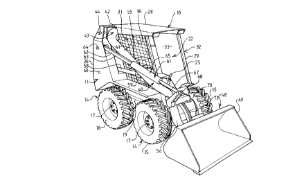
Referring now to the drawings, a skid steer loader vehicle 10
comprises a body 11 having a front end 12 and a rear end 13. The body 11
is provided with ground engageable propulsion means 14 comprising a pair of
front wheels 15 disposed forwardly of a pair of rear wheels 16. The vehicle
10 is propelled in a straight line folw~rdly or rearwardly by driving all four
wheels or, to steer the vehicle, by driving the wheels 15 and 16 on one side at
a different speed and/or direction than those on the other side. Such skid
steer loaders have a high degree of manoeuvrability and to facilitate skid
steering and in particular, for example, the ability of the vehicle to turn about
a central axis of the ground engageable propulsion means the wheel base is
made, in the present example, slightly shorter than the track of the vehicle
although, if desired, the wheel base may be the same or longer than the track
if desired.
~03~536
14
The wheels 15, 16 are carried on stub axles 17 which project ou~w~rdly
from a pair of transversely spaced side members 18, 19 of the body 10 and
which extend fore and aft of the vehicle. Between the side members 18, 19
is a tr~ncmiccion compartment 20 which houses a l~ ",iccion 21, hereinafter
to be described in more detail, whilst above and forwardly of the l~,.c",iccion
compartment 20 is an operator's compartment 22 in which is provided an
operator's seat 23, m~ml~lly operable propulsion controls 24 for controlling thespeed, selecting forward and reverse movement, and steering the vehicle and
m~nll~lly operable loader controls 25 for controlling a loader arm and material
h7n-1ling implement as hereinafter to be described.
The operator's compartment 22 is also defined by a pair of upst~n~ing
members 26, 27 which extend upwardly from the side members, 18, 19 on
opposite sides of the vehicle and by a roof 28 which extends forwardly and
adjacent its forward end is supported by posts 29.
A wire mesh screen 30 is provided on one side 31, of the operator's
compartment 22 for protection of an operator, whilst the other side, 32 of the
operator's co~ a ~l..ent is unobstructed and provides an access opening 33
whereby an operator can enter and leave the operator's compartment 22.
Behind the tr~ncmi.ccion compartment 18 and operator's compartment
22 is provided an engine compartment 34 in which an engine 35 of any
suitable type is housed. In the present example the engine is an air-cooled
diesel engine but any other suitable engine may be provided.
Loader Boom Assembly
The vehicle is provided with a loader arm boom assembly 40 which
is disposed adjacent the one side 31 of the operator's compartment 22. The
loader arm assembly 40 comprises a lift arm assembly 41 which has a pivot
member 42 projecting from an inner end 43 of the lift arm assembly 41 and
extends transversely of the body and is pivotally mounted on the body by
pivotal mounting means 44, 45 provided on the upst~n~ling members 26, 27
respectively. The lifting arm assembly 41 has an implement carrying member
46 which projects from an outer end 47 of the lifting arm assembly and
r 2 0 ~ 6 5 ~ ~
eYte-n~lc ~ e,~ely across the front end of the body and has a material
h~nlning implement 48 carried thereby so as to be disposed folward of the
front end 12 of the body 11. In the present example the implement 48 is an
earth moving bucket 49 ~lthou~h if desired other material h~nrlling
implen~ b may be provided, such as forks.
As shown in Figure 4, the pivotal mounting means comprise a pivot boss
44_ welded in an al)clLure provided in an inner plate 27a of the upst~n~in~
member 27 and a pivot pin 45 is fixed therein. At its other end the pivot pin 45 is
fixed in a further pivot boss 45_ which is welded in an ap~.lu,~ in an inner plate
26_ of the upright 26 and a do~vllwd~dly in~lin~ part 28a of the roof plate 2~.
At its free end t_e pivot member 42 has a bea~ g housing 42a welded
therein and the l-ol~c;ng 42a carries a bush to rotatably mount the pivot
member 42 on the pivot pin 45. At its other end the pivot member 42 has a
further bc~ill~ hol~cing 42b in the form of a bush welded in an OpClliilg
formed in the pivot lllellll~cr 42 where it merges into a major part 55 of the
lift arm ~csçmhly 41 and the bearing hol~sin~ 42b again houses a suitable
bealing bush to pivotally mount the pivot memher 42 on the pivot pin 45. The
inner plate 26a is cut away in this region, as shown at 26a' in Figure 1~, to
~cco-..-..odate the boom ~csembly.
The lift arm ~csembly 41, pivot member 42 and implement carrying
member 46 are formed as a um~ member by bending a steel tube to t_e
desired shape. It will be seen that the lift arm ~csçm~hly 41 colll~lises a major
part 55 which eyten~lc generally rectilin~ly from the inner end 43 towards the
outer end 47 and a minor part 56 which eYtçnds generally duwllwardly and
folw~dly relative to the main part 55 and is disposed bel-.een the main part
55 and the impl~ nt carrying lllelllbcr 46. As best shown in I~iguleS 4 and
S an internledi~te part 57 i. provided between the main and minor parts 55,
56 which is inrlined fo.wardly and ~ ely inwardly so as to position the
minor part 56 within the front wheels 15 and in front of the operator's
C~ .%. ~ ~.
~ .
~ ~ ~ 3 6 5 3 ~
16
A hydraulic lift ram 58 is pivotally connected between a bracket 59
welded to the lift arm ~sembly 41 and the ~lpst~n~ling member 26 about an
axis indicated at 60. The pivotal co.. ~ on of the lift ram 58 to the upright
26 at the axis 60 co~ ,ises a pivot pin 60a which is fixed in pivot bushes 60~2
welded in open.~ provided in the inner plate 26~, and an outer plate 26b
and a further plate 26c of the upst~n~ling member 26. The cylinder of the
ram 58 is pivotally m~nted on the pivot pin 60a The lift ram 58 when
~ctu~ted is adapted to raise and lower the lift arm assembly 41 between a
lower position shown in Figures 1 to 4 in full line and a raised position shown
in chain dotted line in Figure 2.
An implement levelling link is indicated generally at 61 and colll~lises
a first link 62 which col~ ises a bar 63 pivotally connecte-3 to the upst~n~lingmember 26 about an axis 64 and connected to a ram 65 from a cylinder 66 of
which a piston rod 67 projects fol~vardly and is pivotally co~n~cled to one end
of a first lever 68. The pivotal connec~ion of the first link 61 colll~lises a
pivot pin 64a fixed in pivot bushes 64b welded in a~ellurcs in the inner and
outer members 26a, 26b rcspe~ cly whilst the bar 63 is pivotally mounted on
the pivot pin 64a
The first lever 68 is pivotally mollnted on the lift arm ~csembly 41 by
a pivot member 69 and is co~ c~led by a torque tube 70 to a second lever 71
which is pivotally co~ led at its outer end 72 to a second, fixed length link
73 which is pivotally conncc1ed to the bucket 49 as shown at 74.
The re;.~i~c positi~nc of the axis of pivot of the lift arm ~csemhly
41 provided by the pivot pin 45 and the connecl~on of the implement levelling
link to the ~ ding member 26 at axis 64 together with the length of the
first and second levers 68, 71 and the posilion of pivotal co~ e.~;on of the
second link 73 to the bucket 49 at 74 together with the positiQn of pivotal
connection of the bucket 49 to the implement carrying member 46 at 75 is
~l~d so as to provide a linkage which e~ures that the orie,nt~tion of the
bucket 49 relative to the body is presel~ed illcsllc.,li~c of the ~n~ r position
2 ~ 3 ~ 5 ~ ~
of the lift arm ~ccemhly 41 so long as relative movement does not occur
between the piston rod 67 and cylinder 66.
When it is desired to pivot the bucket u~wardly, i.e. cause it to rotate
about the axis 75 in a clockwise direction as viewed in Figure 2, fluid is
supplied to the cylinder 65 to act on the larger di~meter side of the piston
therein so as to force the piston rod 67 out of the cylinder 65 so that the
above descnbed lin~e causes the desired clockwise movement of the bucket
49. Such movement is generally required in operation to lift or tear out earth
and hence is known as ~tear out~ lllo._lllent. Rec~lse the fluid is OpClati~_
upon the whole aoss-section~l area of the piston a relatively high power
action is provided in this direction.
When it is desired to rotate the bucket in an anti-clockwise direction
as shown in Figure 2, commonly known as ~lulllpiL.g~ then fluid is supplied to
act on an ~nn~ r surface of the piston sullounding the piston rod 67 so that
a sm~ller aoss-sec~ion~l area is acted upon and therefore a faster, although
less powerful action, is provided.
At the front end 12 of the side member 18 there is provided an
ab~smçnt surface 76 proYided by a bar 77 welded to a cam plate eYtçn~ion 78
of the side member 18 (see Figure 3). The bar 77 is adapted to abut a flanged
roller 79 rotatably mounted on a spigot 80 projecting from the free end of the
hlll)lcment c~l.ying ~clllber 46. The abutment surface 76 col,lpl;ses a lower,
generally vertical surface part 81 and a forwardly and upwardly inrlin~d part
82, the surface parts 81 and 82 being c~ o!~-cd to co-operate with the roller
79 as the lift arm ~ccçmhly 41 approaches its lo._llllosl ~os;lioll and to
e~_lll re~ward displacçmPnt of the free end of the impl~m~nt c~l~-ng
member 46 when in such a lower position, for example, when driving a vehicle
folwardly to load the bucket 49. If desired the al~ullllenl surface 76 may be
eYtçnded upwardly so as to SUppOl l the member 46 over a greater height.
From the foregoing it will be seen that boom ~ccçmhly 40 e~t~n~ls
folwardly from a position ~ cçnt the rear end of the body 11 ~lQn~cide the
one side 31 of the operator's co~-~r~ ent 22 whilst the other side 32 is
~ 20~653 ~
18
unobstructed so that an opPlalor can gain accesss to the CQlllp~ ent through
the access olJcl~ill~ 33.
By providing the axis of pivot of the lift arm assembly 41 adjacent the
top rear corner of the operator's co..-i~z~ ent the operator is provided with
the ability to lift the bucket to a relatively great height and at the same timeprovide the bucket with good reach and the vehicle with a stability. For
example, the axis of pivot of the lift arm Acsemhly is ap~r~-;...Ately 15m abovethe ground in the example illustrated, whilst the tlict~nce l~ .ecn the axis of
pivot of the lift arm ~cce.mbly and the axis of pivot of the bucket about the
axle 75 is a~pro~ tely 2Sm. Hence the vehicle has a total lift of
a~i~;...Ately 3m and over the whole of this range of lift the pivotal
connPc~ion 7S to the bucket lies folw~rdly of the front end 12 of the vehicle.
Propulsion and Loader Controls
The llA..~...;CCion 21 c~ ises a pair of con~l-t;QnAl swash plate
l~os~lic pumps 90, 91 the output of wWch is se~t, in co~ ;on~l m~nnPr,
to a conventional hyd~ ic motor 92 (see Figure 2). In this example the
rearmost pump 90 provides a feed to the motor 92 on the left-hand side of the
vehicle whilst pump 91 provides feed to the corresponding pump, not shown, on
the right-hand side of the vehicle.
The pumps 90, 91 each have an input member 93, 94 respectively
which are rotatable about spaced parallel axes which eAtend perpendicular to
a fore and aft axis of the vehicle and which lie in a sllbst~nti~lly holi~onlal
plane.
The input ~e~bel~ 93, 94, in the present eA~plc, control the angle
of the swash plates of their ~sor~ted hydraulic pump through the
intermediary of a hydraulic servo .~.rchA~ .. in-built into the hydraulic pump
in col-.e-.l;onAl ~.A~..er. If desired, ho~.e~r, the input members 93, 94 may
dire~;~ mech~nically ~ te the angle of the swash plates again in
Con~ l;on~l m~nner.
The vehicle is provided with a suitable linlcage to co~c~l the
m~ml~lly operable propulsion control means 24 to the input members 93, 94
2036536
19
in order to achieve a desired regime of swash plate angle control. Such a
regime is illustrated in Figure 6 which shows the desired swash plate angle and
hence desired input member 93, 94 positioned for different positions of
propulsion control member ~n~ r position. The graphical representation of
Figure 6 assumes that the propulsion control member 95 is, in each ~n~ r
position moved to fullest extent possible but the same pattern of swash plate
control would be achieved for lesser amounts of movement in any particular
direction although the extent of movement of the swash plates of each pump
would be correspondingly reduced.
When the control member 95 is moved to its fully forward position,
i.e. parallel to the fore and aft direction of the vehicle (referred to in Figure
6 as 0~) both input members 93, 94 are rotated, in the example illustrated, in
a clockwise direction as viewed in Figure 2 or Figure 7 so as to cause forward
movement of both the left-hand and right-hand propulsion means.
When the lever is moved 4S to the right (referred to in Figure 6 as
4S) the linkage causes the input member 94 to adopt a position at which the
swash plates deliver no fluid to the motor, i.e. a neutral position, whilst the
input member 93 of the swash plate which drives the left-hand motor 92 is
m~int~ined in its fully forward position so that the vehicle is caused to turn to
the right.
Movement of the member 95 in a direction at 90~ to the right
(referred to in Figure 6 as 90~) causes the input member 94 to move to signal
the swash plates to move fully to a reverse drive position whilst the input
member 93 is m~int~ined in its fully forward position and hence the vehicle
is caused to turn on its axis.
Movement of the control member 95 to a position 13S to the right
causes the input member 94 to be m~int~ined in its full reverse position whilst
the input member 93 is moved to a neutral position in which no output is
produced by the swash plates.
When the lever 95 is moved in a reverse direction parallel to the fore
and aft axis of the vehicle, (referred to in Figure 6 as 180~) the input member
;~03~5;~6
94 is m~int~ined in its full reverse position whilst the input member 93 is
moved to a full reverse position.
A similar sequence of movements occurs when the lever 95 is moved
to corresponding positions to the left, referred to in Figure 6 as 225~, 270~ and
315~.
A mechanical linkage which aims to provide the above described
regime is illustrated in Figure 7. Each input member 93, 94 is provided with
an input lever 96, 97 respectively and these levers are connected by ball jointsat positions A1, A2 to respective links 98, 99 which are connected by ball
joints at A3, A4 to the lower end of an operating lever 100. The points A1,
A2, A3, A4 all lie in a plane which is parallel to and spaced above a plane
which contains the axes of rotation of the input members 93, 94.
The operating lever 100 is pivotally mounted to a part 101 of the body
11 for univel~al movement by virtue of a parallelogram linkage 102. The
linkage 102 collll~lises a ffrst Hookes joint 103, one yoke 104 of which is fixed
to the top end of the operating lever 100 and is also fixed to one yoke 105 of
a second Hookes joint 106, the other yoke 107 of which is fixed to the part 101
of the body. The second yoke 108 of the first Hookes joint 103 is connected
by a link 109 to a first yoke 110 of a third Hookes joint 111, the second yoke
112 of which is connected to a ffrst yoke 113 of a fourth Hookes joint 114, the
second yoke 115 of which is fixed to the part 101 of the body. In addition, the
second yoke of the third hooks joint 111 carries the propulsion control
member 95. Thus movement of the control member 95 in any one of the
radial directions described hereinbefore permitted by the fourth Hookes joint
114 will be transmitted by the link 109 and Hookes joint assembly 103, 106
to the operating lever 100. The line joining the points B of connection of the
Hookes joints 106 and 114 to the part 101 of the body lies parallel to a line
joining the parts A1, A2 but in a plane spaced above the plane cont~ining the
parts A1 - A4.
Hence movement of the propulsion control member 95 in, for
example, the forward direction F parallel to the fore and aft axis of the vehicle
5 3 ~
will, by virtue of the described parallelogram linkage, cause a corresponding
movement of the points A3, A4 in the reverse direction Rv which will cause the
input members 93, 94 to rotate in a clockwise direction to provide an output to
the pumps to cause the vehicle to advance fo, ~dly. Similarly, movement of the
control member 95 in the reverse direction Rv will cause movement of the points
A3, A4 in the r~ ~d direction F and the collcsponding anti-clockwise rotation
of each of the input ,nt.~s 93, 94 to provide reverse movement of the vehicle.
Movement of the lever 95 in the direction R, i.e. to the right of the
vehicle at right-angles to the fore and aft axis, causes mo.cl.lenl of the points
A3, A4 to the left to cause the input member 93 to rotate in a clockwise
direction so that the left-hand ground engageable propulsion unit is driven
folwar~y whilst the input m~mher 94 is rotated in an anti-clockwise direction
to cause the right-hand ground engageable propulsion unit to rotate in a
reverse direction, thereby c~ g the vehicle to spin on its a~cis.
If the member 95 is moved to the left in the direction of the arrow L
then the points A3, A4 are moved to the right in the direction of the arrow R
thus c~llcing the m~mber 93 to rotate anti-clockwise to cause the left-hand
propulsion unit to provide reverse dAve whilst the input member 94 is caused
to rotate clockwise so that the Aght-hand propulsion unit is caused to rotate
fol~.ardc, again c~cing the vehicle to rotate on its axis but in the reverse
direcdon, i.e. to the left.
Movement of the lever 95 at 4S to any one of the directions described
heleillbefore causes a co.ub~ation of modons to take place. For cA~,~le, if
the control lever 95 is moved 4S to the right, i.e. midway between the folwa~d
and rAght-hand posit;ons illustrated in Figure 7, then there will be a
colresponding ~o.~ ent of the points A3 and A4 at 4S midway between the
Rv and L directions shown in Figure 7 having the effect of ...~inl~;..;ng the
input member 94 in its neutral position so that no drive is provided to the
right-hand ground engageable propulsion means whilst the input member 93
is moved fully clockwise to provide full fo~ rd drive to the left-hand
propulsion means, thereby c~ Cing the vehicle to steer to the right. A
20365;~6
~
corresponding combination of motions occurs for movement of the lever 95 at
other 4S angles and at other positions a combination of motions of the control
members 93, 94 is obtained sust~nti~lly in accordance with Figure 6.
In one particular example the dimensions of the linkage are as follows,
although it will, of course, be appre~te~l that other dimensions may be
provided as will be apparent to a person of skill in the art.
Dimension mm
C 240
D lS0
E 100
G S0
H 30
180
J 45
K 305
M 90
N S0
p 440
The control force ratio between sideways movement of the control
member 9S and the forward and reverse movement can be varied by altering
the length of the links 99 which, in the illustrated example are 150mm long,
which with a distance between the points A1, A2 in the neutral position of the
pumps of 240mm gives a 4S angle between the links 99 and the line joining
the points A1, A2. By m~king the links longer the force required for sideways
movement of the member 9S will be greater and the extent of sideways travel
smaller and would give the control member 9S a bias towards straight line
travel.
Figure 8 illustrates an alternative hydraulic linkage in which the
hydrostatic pumps and motors are as described in connection with the Figure
7 embodiment and the input members 93, 94 again have input levers 96, 97
respectively. However, the levers 96, 97 are connected to piston rods 120, 121
of double acting hydraulic rams 122, 123 respectively. The hydraulic rams 122,
123 are pivotally mounted to a part 124 of the body 11 about vertical axes 125,
~ 2~3~S3 ~
126 respec~ely which are parallel to the axis of rotation of the input members
93, 94.
The pi ton rods 12Q 121 are provided with piston heads 120~, 120b;
121a, 121b r~ecliv~ly and the rams 122, 123 are provided with corresponding
cylinders 122a, 122b; 123a, 123k ~ )e~;lively which are provided with inlet ports
127a, 127_, 128a, 128b respectively.
Each input lever 96, 97 is ~cco~qted with a cc~-~r..-g lever 130, 131
respecli~ely which are pivotally mollnt~pd as shown at 132, 133 to a fixed part
134 of the body 11.
The centring levers 130, 131 are pivotally biased together by coil
tensions springs 1353, 135b and carry balls 1363, 136b; 137~, 137b respectively
which engage abutmPnt parts 138~, 138b; 1393, 139b res~c~ ly of the input
levers 96, 97. If desired, inctead of two springs a single spring inter-conn~pcting
the levers 130, 131 may be provided. The pivots 132, 133 are positiQnPd so
that when the input members 93, 94 are in their neutral positiQnC so that the
swash plates are providing no output the abutm~pnt portions 138~, 138b; 139~,
139b are each engaged by their ~ssor~ted ball 136~, 136b; 1373, 137~ of the
associated cell~mg lever 130, 131 so that the input members 93, 94 are biased
to~ards their neutral position from any displ~cem~nt in either direction
thereLom and hence are normally m~int~ined in their neutral position in the
~bsence of any input. It should be apprec;ated that the above described
ce~ g means may be equally applied to the m~och~nical linkage described
with referel,ce to Figure 7 but has not been illustrated in Figure 7 for clarity.
Refelling now to Figures 9a and 9b, the propulsion control member
95 is lu"~el~ally mollnted about a point P by a suitable u~ el~al joint 140 to
a base part 141 which, in the pr~en~ e~llpl~ is fixed relative to the body 11.
At its upper end the control member 95 has a knob 142 which can be
g~ cd by the o~elator.
~ dj~ce-nt the lower end of the member 95 is a valve opelat,ng sllrf~ce
member 143 which provides a part spherical valve operating surface which is
engaged by valve operating plungers 144 - 147 which are disposed at equal
Z0365~6
24
distances from the universal joint 140 and on planes cont~ining the point of
pivot of the joint 140 and are equally ~n~ rly spaced therearound lying in
planes inclined at 4S to a line through the joint 140 and parallel to the fore
and aft axes of the vehicle.
The plungers 144 - 147 are spring biased into engagement with the
surface member 143 and, in themselves, would tend to bias the member 95
into a vertically upward position as shown in Figure 9 with an equal bias to
return the member 95 to the neutral position when displaced therer. olll in any
direction.
In order to provide a bias towards movement of the control member
95 in a forward and reverse direction two further spring bias plunger members
are provided as illustrated at 148 and disposed on opposite sides of the
uluvel~al joint 40 on a line perpendicular to the fore and aft axis of the
vehicle. The spring bias provided by the plungers 148 is significantly stronger
than that provided by the plungers 144 thus a stronger bias to return the
member 95 to the vertical occurs when the member 95 is displaced from the
vertical to the left or the right than when it is displaced from the vertical ina forward or reverse direction. This provides the vehicle with a bias towards
forward and reverse movement of the member 95 with stronger operator force
being required to cause steering movement of the vehicle to the left or the
right thereby facilitating forward or reverse driving of the vehicle and in
addition m~king the vehicle safer.
The valve operated by the plunger 144 is arranged to feed hydraulic
fluid under ~es~ule when the plunger 144 is depressed to the port 127b of the
ram 122 to cause the input member 93 to rotate cloc-k-wvise to provide forward
drive to the left-hand propulsion unit. Similarly, the plunger 147 is arranged
to cause its associated valve to feed fluid to the port 128b of the ram 123 to
cause the input member 94 to operate the right-hand propulsion unit in a
forward direction.
Depression of the plunger 145 causes its associated valve to feed fluid
to the port 128a of the ram 123 to cause the member 94 to rotate in an anti-
20365;~6
clockwise direction and to cause the right-hand unit to drive in reverse, whilstdepression of the valve member 146 causes its associated valve to feed fluid
under pressure to the port 1273 of the ram 122 to cause the member 93 to
rotate anti-clockwise to cause the left-hand unit to drive in reverse.
When the member 95 is moved to the right plungers 144 and 145 are
depressed c~llsing forward movement of the left-hand unit and reverse
movement of the right-hand unit so that the vehicle spins on its axis to the
right. Similarly, movement of the member 95 to the left depresses the
plungers 146 and 147 to cause the left-hand unit to rotate in reverse and the
right-hand unit to operate forward to cause the vehicle to spin on its axis in
a left-hand direction.
When the lever 95 is moved at 4S, for example, at 4S between the
forward and right directions, the valve 144 only is depessed so that the left-
hand unit is caused to drive forward whilst the right-hand unit remains at its
neutral position since neither of its operating plungers 145 or 146 are
depressed. A similar depression of only one plunger occurs at each of the 4S
positions with associated movement only of one of the propulsion units in
accordance with the regime of Figure 6. Movement of the control member 95
to positions intermediate the 4S positions described hereinbefore causes a
combination of movements in accordance with the valve members which are
depressed and their extent of depression.
In the above described hydraulic linkage system the m~xi~
displacement possible of the propulsion control member 95 in terms of its
~n~ r rotation about a holL~oll~al axis passing through the point P varies in
accordance with whichever of the various directions in which it is displaced.
For example, when the control member 95 is moved in a forwards direction
so that the valve operating members 144 and 147 are displaced downwardly,
then for a given extent of valve operating member displacement the control
member 95 will move folwardly further than would be the case if it were
moved, for example, at 4S to the right so that only the valve member 144
were displaced dowllwaldly. This is because the radial distance of the line of
2036536
26
action of the valve operating members 144, 147 is closer to the axis of pivot
of the member 95 than is the valve operating member 144, thus the control
member 95 is moved to a greater extent in each of the forward, reverse and
left and right positions compared with intermediate positions at 4S
therebetween and the upper line in Figure 6 illustrates this.
A similar differential in the extent of control member movement
occurs with both the rigid mechanical linkage described above and the flexible
mechanical linkage now be be described.
Referring now to Figure 10, there is shown an alternative mechanical
linkage lltilicing a pair of flexible push-pull cables 150, 151. An inner memberl50a of the cable 150 is connected to the propulsion control member 95 so
that forward movement, F, of the member 95 pulls the inner member l50a out
of its outer case l50b whilst reverse movement Rv of the lever 95 pushes the
inner member l50a relative to the outer member l50b all with respect to a
neutral position of the lever 95. Similarly, the inner member l51a of the other
cable 151 is connected to the member 95 so that movement of the lever 95 to
the left, L from a neutral position pulls the inner member l51a out of its
outer member l51b whilst movement of the member 95 to the right R, pushes
the inner member l51a into its outer member l51b.
The outer members l51a and l51b of the cables 150, 151 are
anchored, at their ends adjacent the member 95 to a fixed part 152 of the
body 11.
At its other end the outer member l50b is anchored to a fixed part
153 of the tr~ncmiccion 21 whilst the inner member 150a at this other end is
pivotally connected to a parallelogram linkage 154 at point A.
The outer part l51b of the cable 151 is anchored at its other end to
the parallelogram linkage 154 at point B whilst the inner member 151a at this
other end is anchored to the linkage at point A.
The linkage colllplises four equal-length links 155 - 158. The links
155 and 156 are connected together at their one ends and to the inner
members 1513, l50a at point A. At its other end link 155 is connected to
20;~6536
27
input lever 96 at point C which is also connected to link 158 the other end of
which is connected to the outer member 151b at point B and also connected,
at this point, to link 157 the other end of which is connected to input lever 97at point D to which link 156 is also connected.
In use, movement of the lever 95 in a forward direction, F, will pull
the inner member 150a through the outer member 150b so as to cause the
point A of the linkage to move up right in Figure 10 and hence to cause both
input levers 96, 97 to rotate clockwise to cause both pumps to cause forward
drive of their associated propulsion means. Movement of the lever 95 from
the neutral position in the rearward direction Rv will cause movement of the
point A down in Figure 10 and hence anti-clockwise movement of the input
members 93, 94. Movement of the lever 95 to the right, R, will cause
movement of inner member 151a to move the point A to the left to cause the
input levers 96, 97 to rotate in opposite directions so that the points C and D
approach and hence so that input member 93 rotates clockwise to cause
forward driving movement of the left-hand propulsion unit, whilst the input
member 94 rotates anti-clockwise to cause reverse movement of the right-
hand propulsion unit.
When the member 95 is moved to the left, L~ from a neutral position
then the member 151a will be moved to move the point A to the right so that
the input levers 96, 97 will rotate in opposite directions away from each other
so that input member 93 is caused to rotate anti-clockwise to give reverse
drive at the left-hand propulsion unit whilst the input member 94 is caused to
rotate clockwise to give forward drive to the right-hand propulsion unit.
When the lever 95 is moved to a position at 4S to any of the
orthogonal positions described hereinbefore, for example 4S to the right
between the forward and right positions, the linkage will move such that the
operating lever 97 of the pump to the right-hand propulsion unit will remain
in its neutral position shown in Figure 10 whilst the operating lever 96 to the
left-hand pump will be moved to its folward position and a similar
combination of motions to achieve the regime shown in Figure 6 will be
~ ~n~53 ~ '
28
achieved for other directions of movement of the lever 95 in an analogous
m~nner to the motionc described hereinbefore in conl~c~;on with the other
"~ech~ l linkage and hydraulic linlrage.
Motor and Stub A~de Mou~
The side members 18, 19 each coul~lise a loop case co,..pzr~ cnt and
as best shown in Figures 4 and 11 each colll~,lise a transversely inner wall 160and a transversely outer wall 161 which are joined by top and bottom walls 162,
163 and end walls 164, which provide and oil tight co.ll~ lent.
It will be seen that the outer walls 161 provide main chassis members
of the vehicle body and that at the rear of the vehicle extensions of. the outerwalls provide the inner side plate of the upst~n~in~ members 26, 27, (see Figure4). In addition, a transversely ext~n~in~ member 165 (Figure 11) i--l~ reo~ects
the main chassis members 161 together and provides a floor to the body.
The loop case co~ ents 18, 19 have mollnte~l thereo4 at the
po.cihonc shown in Figure 2, the ground engage~ble propulc;~n wheels 15, 16
and the motors 92.
Refel.i.lg now particularly to Figure 11, there is illustrated the
mo....~ g of one of the ground propulsion wheels 16 on the loop case
c~ ent 18 although it should be apprer:~te~l that each of the four wheels
is mounte~l on its associated loop case co~pz~ enl in exactly the same
...~nner and do not re~luire separate description.
At the loc~tion of the wheel 16 the outer wall 161is provided with a
circular o~g 166 which provides a first guide means which co-operates with
a second guide means provided by a rebate 167 of a carrier member 168 of
generally frusto-con;~l co ~ ation and formed integrally with a stub axle
housmg ~- e~ber 169. The stub axle h~ g member 169 carries taper roller
l~ alil.~ 170 so that a stub axle 171 is hollsed by the member 169 so as to be
rotatable about an axis of rotation 172.
The wheel 16 is bolted to one end of the stub a~e 171 in con~,enl;on~l
m~nner by bolts 173 whilst a driven wheel in the form of a sprocket 174 is
bolted to the other end of the stub axle 171 by bolts 175.
2036536
29
The stub axle and its housing, together with the carrier member 168
are configured so that the sprocket 174 is disposed within the loop case
compartment 18. The teeth of the sprocket 174 are offset from a central
mounting part of the sprocket so that the sprocket can be fastened to the stub
axle 171 in a reverse orientation, shown in dotted line in Figure 11, when
attached to the stub axle for the other wheel on the same side of the vehicle.
The carrier member 168 is formed so that the axis of rotation 172 of
the stub axle 171 is eccentrically disposed relative to the central axis of the
rebate 167 and hence relative to a reference axis 176 about which the carrier
member 168 is col~Llailled to rotate by co-operation between the hereinbefore
mentioned guide surfaces 166, 167.
Clamping means, such as an ~nm~l~r ring 177, are provided to enable
the carrier member 168 to be clamped to the outer wall 161 in any desired
~n~ r orientation around the reference axis 176.
By the above described eccentric disposition of the axis 172 relative
to the axis 176, the position of the axis 172 both longit~rlin~lly and vertically
of the vehicle can be adjusted thereby pe~ i,lg of adjustment of the wheel
base of the vehicle, in association with driving chains of ~propliate lengths,
as well as permitting of adjustment of the ground clearance of the vehicle
together with providing a facility for tensioning a chain of a given length.
It will be seen that the stub axle 171 is supported solely from the side
wall 161 without any support being afforded by the inner wall 160 thereby
avoiding the need to effect any m~çhining operations on the wall 160 which
would otherwise be necessary if the stub axle were additionally supported
thereby.
In addition, a clearance is provided between the sprocket member 174
and the wall 160 to permit of manipulation of a chain through the space and
hence into driving relationship with the teeth of the sprocket 174.
Referring now to Figure 12, there is shown the mounting of a motor
92 on the loop case colllpal Illlent 18.
Z036536
The motor 92 is a collvenlional commercially available high torque
motor and has a convelllional output shaft 180. The motor 92 has a mounting
flange 181 by which it is bolted to a mounting plate 182 welded to the inner
wall 160 of the compartment 18. The mounting plate 182 has a rebate 183
which is received within a circular aperture 184 formed in the wall 160 to aid
location of the ring 182.
A sleeve 185 is m~chined to provide a pair of driving wheels in the
form of sprockets 186, 187 and an inner part 188 of the central passage of the
sleeve 185 has the output shaft 180 received therein with a splined connection
189 provided therebetween.
A seal 186a is provided in the central passage and a shaft seal 186b
is also provided so that lubricating oil for the splined connection 189 suppliedfrom the motor 92 is caused to flow via bore 186c to lubricate the bearing
190 before relulllhlg to the motor.
A taper roller bearing 190 is provided between the external surface
of the sleeve 188 and a seat 191 provided by the body 192 of the motor 92.
A bracket member 193 in the form of a three-legged spider is bolted
to the pump body 192 by bolts 194, only one leg l9S and one bolt 194 being
shown in Figure 12, the other two legs and bolts being equally ~n~ rly
disposed around the axis of rotation of the output shaft 180A further taper
roller bearing 196 is provided between the bracket 193 and an outer surface
part of the sleeve 185.
A brake drum 197 is formed with a boss 198 which is received within
an outer part 199 of the central passage of the sleeve 185 and is retained in
splined engagement therewith, as shown at 200 by a bolt 201. The sleeve is
provided with a l~al~vel~ely extending passage 202 to receive a locking pin for
the bolt 201.
Chains, such as roller chains, not shown, are looped around the
respective sprockets 186, 187 and the respective driven sprockets 174 and the
sprocket, not shown, of the other wheel.
2036536
31
To assemble the sprocket and chain drive, initially the chains are
manoeuvred into the compartment 18 through an opening 203 provided in the
outer wall 161 and are passed between the inner wall 160 of the CO~ ~ LllleIlt
18 and the respective driven sprocket such as the sprocket 174. At this stage,
although the motor 92 is bolted in position, the sleeve 185 and bracket 195 are
absent.
The sleeve 185 is then offered up the outward shaft 180 and the
chains are then manoeuvred over the outer end of the sleeve 185 and into
position on their associated sprockets 186, 187. The hereinbefore described
eccentric mounting of the stub axles permits the stub axle axes 172 to be
moved towards the motor 92 to provide sufficient slack in the chain for the
above manipulation to occur.
The bracket member 195 is then bolted in position with the chains
passing through the spaces between the legs 195 thereof. Thereafter the
brake drum 197 is bolted in position and ffnally an extension housing
enclosure member 204 is bolted in fluid tight relationship to the outer wall
161.
In the assembly described with reference to Figure 12, the output shaft
180 and the associated driving sprockets 186, 187 and brake drum 197 are
supported entirely from the motor through the bracket 195 and receive no
support from any component which is independent of the motor and in
particular do not receive any support from the outer member 161. It is
therefore unnecessary to perform any m~ ining operation on the member 161
other than the simple formation of the clearance opening 203 which may be
made, for example, by flame c~ltting~
If desired, the motor described above may be mounted on the outer
wall 161 instead of the inner wall.
Instead of driving the stub axles from a shaft motor through loops, if
desired, the stub axles may be driven by other means such as, by providing a
separate motor which may drive each stub axle directly. In this case, if desired
2036S36
the above described eccentric mounting may also be provided with the motor
similarly moving eccentrically with the stub axle.
Operator Restraint
Referring now to Figures 13 - 15, a restraint member 210 is provided
which is mounted on the body by a lever 211 for movement between operative
and inoperative positions. The operative position is shown in Figure 13 and
in this position the member extends transversely of the operator's
compartment 22 in restraining relationship with the seat 23 so as to restrain
an operator seated on the seat accidentally falling forwards should, for
example, the vehicle come to a sudden halt or tip forwardly. The inoperative
position is shown in Figure 14 in which the lever 211 has moved from the
generally upwardly position it occupies when the restraint member 210 is in
its operative position to a generally forwardly extending position so that the
restraint 210 and lever 211 are disposed so as to permit of passage of an
operator into and out of the seat 23 through the access opening 33.
The lever 211 is pivoted to the body 11 by suitable pivot means, about
an axis 212 which extends transversely of the vehicle. A rigid strut 213 is
pivotally connected to the lever 211 at one end and is provided with a ratchet
which may engage a ratchet member to lock the lever 211 in its operative
position, as hereinafter to be described in more detail with reference to Figure15.
In the embodiment illustrated in Figures 13 and 14 restraint member
210 extends in cantilever from the lever 211. The lever 211 also carries an
arm rest element 214 which pivots with the lever 211 and restraint 210. On
the opposite side of th operator's compartment hereinbefore referred to as the
"one" side 31 a fixed arm rest element 215 is provided which is fixed relative
to the seat 23 and the restraint 210 has a rearwardly directed part 216 which
co-operates with the fixed arm rest element 215 so as to fully restrain the
operator.
In the embodiment shown in Figures 13 and 14 the propulsion control
member 95 of the hereinbefore described mechanical rigid linkage is provided
X03~536
and hence is mounted on a fixed part of the body 11 and so, as shown in
Figure 14, does not move with the lever 211 but as it is disposed on said one
side 31 of the body it does not interfere with access of an operator through
the access opening 33 on said other side 32 of the body.
Also provided on said one side of the compartment mounted on a
fixed part of the body is a speed control 217 for the engine.
The lever 211 carries the m~ml~lly operable loader control 25 which
operates the valve means as described hereh~rore, the valve means being
connected to the lift and implement operating rams by flexible hydraulic pipes
which pass down the lever 211 and exit therefrom adjacent its lower end and
pass to their associated rams. The flexible pipes, of course, permit of the
hereinbefore described pivotal movement of the lever 211.
Referring now to Figure 15 which shows a modification of the
restraint shown in Figures 13 and 14. In this modification the restraint 210 is
supported not only by a lever colles~onding with the lever 211 described
hereinbefore but, in addition, at the opposite end thereof by a second similar
lever 211a which is pivotally mounted about the same axis 212 as the lever
211 and which carries a further arm rest element 214a. As shown in Figure
15 the rigid strut 213 is provided with ratchet teeth 218 which co-operate with
a ratchet member 219 which is provided with a co-operating guide 220 to
constrain the link 213 from excessive pivotal movement away from the ratchet
219. In addition the link 213 has a transversely extending lug 221 at its lower
end which can be engaged by a foot of the operator to enable him to pivot the
link 213 ulJw~rdly out of engagement with the ratchet 219 to permit of
movement of the restraint from an operative to an inoperative position.
Alternatively a ratchet mech~ni.cm operated by a trigger or other m~nll~lly
operable mech~nicm on or adjacent the restraint may be provided. Such
movement is aided by providing gas springs 222 of conventional type.
The lever 2113 carries the propulsion control member 95 of the kind
used when the linkage is the hydraulic or flexible mechanical linkage described
34 ~ ~ ~ 3 6 5 ~ ~
hereinbefore. In either case the flexible hydraulic pipes or mech~nical push-
pull cables permit of pivotal movement of the lever 211a about the pivot 212.
If desired, the control means 95 may be mounted on a fLxed part of
the body illespc~ e of the linkage and the resl,aillt 210 may be in that case
su~ ed by either a single lever as shown in Figures 13 and 14 or by two
levers as shown in Figure 15.
The link 213 and gas springs 222 described and illustrated with
reference to Figure 15 are also provided in the embodiment shown in Figures 13
and 14.
In addition, in both embo~lim~ntc a ~exible cable or rigid m~nical
link is provided between the or at least one of the levers 211 and a parking
brake of the vehicle. Such a link is shown at 223 in Figures 13 and 15.
Although in the illustrated examples the propulsion control lever 95
has been described as being on said one side 31 of the opclatol's co...p~ ent
whilst the loader control means 25 has been disposed on said other side 32,
if desired the location of the said controls can be ll~sposed concictent with
the linkage from the propulsion control being capable of accommod~ting
pivotal movement of the lever 211.
In use, the link 223 ellsurcs that the vehicle l,~k ing brake ic off when
the res~ainl 210 is in its Opel';lli~,C, position and is applied when the resllainl
210 is in its inoperative pocition In addition an interlock to the engine is
provided, not shown, which with the rcsll~n~ 210 in its operatiw position
en~les the engine to be co..t;.~ed to run and also enables the engine to be
started but, in each case, only if an opclator is sitting on the seat since an
ition~l interlock is provided sel~ to the presence or ~se-nce of an
o~clator.
When the re~l,~l 210 is moved to an interme~ te position from its
opelati~c position the interlock senses this and causes the engine to be
immobilised.
When the res~l 210 is in its illope~a~ position the interlock
permits the engine to be started and in this case the engine can be started
Z0;~653
even if an operator is not in the seat but only if the parking brake is applied
by virtue of the link 223.
The ratchet teeth 218 are positioned and provided so as to permit of
adjustment of the restraint 210 when in an operative range of positions to suit
different sizes of driver.
Operator's Compartment
The operator's compartment 22 is defined in part by the inner plates
26~, 27a of the upst~n~ling members 26, 27, the roof 28 and the posts 29 which
together provide the enclosure with one side, 31 and a top and rear wall which
include means for preventing access therethrough. In the case of the one side
31 this is by virtue of the presence of the boom assembly and also the wire
mesh protective screen 30. At the rear, the operator's compartment is defined
in part by the front wall 34b of the engine compartment 34. The space
between the top wall 34b and the underside of the pivot member 42 whilst
preve~ g access to the operator's compartment does permit the operator to
look out of the compartment to the rear beneath the pivot member 42.
The inner plates 26~, 27a which in substance define part of the
operator's colll~alllllent are themselves integral col~li"u~tions of the outer
walls 161 of the hereinbefore described side members 18, 19. In the present
example the inner plates 26~, 273, and a contoured base 283 are made by
bending a single plate to the profile shown in Figure 4. The roof 28 is welded
to the plates 26~, 27a. If desired the operator's compartment may be
integrated with other structural members of the body by welding instead of
being formed from a single plate.
Thus it will be seen that the main structural parts of the operator's
compartment which provide the wall thereof are formed integrally with other
structural elements of the vehicle and in particular the side members 18, 19
which provide the loop cases and the upst~ncling members 26, 27 which carry
the boom assembly pivots and thus the operator's compartment is integrated
with the rem~inder of the m~chine and hence has a high ability to withstand
forces exerted thereon during roll-over conditions.
Z0365~6
36
The features disclosed in the foregoing description, or the
accompanying drawings, expressed in their specific forms or in terms of a
means for performing the disclosed function, or a method or process for
~tt~ining the disclosed result, or a class or group of substances or
compositions, as a~)propliate, may, separately or in any combination of such
features, be utilised for re~ ing the invention in diverse forms thereo~