Note: Descriptions are shown in the official language in which they were submitted.
2~36s2z
METHOD AND APPARATUS FOR
BEVERAGE BLENDING AND PROPORTIONING
Field of the Invention
The present invention relates to a method and
apparatus for improving quality and increasing syrup yields
within a beverage blending system. In particular, the
present invention relates to a method and apparatus for
controlling the proportional blending of two or more com
ponents of a carbonated beverage by means of the mass flow
of the components.
Background of the Invention
The preparation of beverages, particularly car-
bonated beverages, includes the mixture or blending in
exact proportion of a flavor syrup with water. The propor-
tion standards for a particular beverage are typically set
by the owner of the syrup recipe and the associated trade-
marks of the beverage. These proportion standards are a
fixed operational requirement for the bottler who is a
licensee of the recipe owner.
Typically, the conformity of the blended beverage
to the proportion standards is determined after the
beverage has been prepared. This determination is made by
a downstream analyzer system or by lab analysis. If it is
found that the already blended beverage does not fall
within the required standards, the batch is disposed of at
substantial cost to the bottler.
There are a number of blending and proportioning
systems found in the prior art. There is shown in Figure 1
7859-2(CIP1).Foreign -1-
/wp/disc#12
2U36U~?
a typical blending and proportioning system including a
proportion analyzer at the discharge end. For purposes of
the present invention this typical blending system need not
be described in complete detail. Reference is hereby made
to U.S. Pat. No. 4,801,471 to Mojonnier which describes a
blending and proportioning system similar to those typical-
ly found in existing bottling plants.
The typical blending and portioning system shown in
Figure 1 herein includes a water input 10 which feeds a
cooler 12. The cooler 12 feeds one portion of a propor
tioner 14. A syrup supply 16 feeds a separate portion of
the proportioner 14. Filtered water from inlet 10 or syrup
from supply 16 may pass through scrubbing units (not shown)
or other apparatus as desired prior to input into propor-
tioner 14. The input flow into the proportioner 14 from
both the water line 18 and syrup line 20 is controlled by
means of valves 22 and 24, respectively. Valves 22, 24
receive control signals from floating control members (not
shown) within the storage tanks 26 and 28 of the propor
tioner 14.
Storage tanks 26 and 28 feed lines 32, 34, respec-
tively, which exhaust into blending tank 30. Water line
32 into tank 30 includes a micrometer or similar type
control valve 36. Valve 36 is used to make minute adjust-
ments in the relative proportion of the water flowing into
blending tank 30. Syrup line 34 may also include a control
valve (not shown). However, due to the large proportion of
water in a typical beverage, as compared to the syrup,
minute control of the relative proportion of the components
is more easily accomplished by adjustment at the water
input. A total flow control value 38 is also provided at
the inlet to blending tank 30.
Blending tank 30 includes a float member 40 similar
to that used along with valves 22 and 24. The signals from
the float member 40 is used to control the downstream
pumping of the blended beverage. The blended beverage from
7859-2(CIP1).Foreign -2-
/wp/disc#12
~o~s~~~
blending tank 30 is input into a carbonator 42. After car-
bonation, the beverage flow is directed towards a bottling
apparatus (not shown).
The actual proportion of syrup and water within the
blended beverage is determined by a downstream beverage
analyzer 44. The analyzer 44 takes samples from the flow
into the bottling apparatus. The samples are used to
determine the accuracy of the blend as performed by the
proportioner 14 and compare it to the fixed standards. If
an on-line analyzer 44 is not provided, periodically
samples are manually withdrawn from the flow and lab
analysis is conducted to determine the proportion result.
Typically, sugar based beverages are analyzed by
making a brix determination of the sugar within the overall
blend. In the case of diet soda, the analyzer typically
uses a titrated acidity determination. Methods of
analyzing the beverage include internal reflection spectro-
scopy and infrared absorbtion.
Upon a finding that the blended beverage is outside
of the standards set by the recipe owner, adjustment of the
proportioning is made at valve 36 or at some other position
within the system. Analyzer 44 may also serve to control
the blend. Such an analyzer/controller typically includes
an external water valve which inputs additional water into
the flow at the position of the analyzer. The system
compensates for errors of the proportional blending by
operating the proportioner on the "high" or rich end of the
blending standards. The addition of water downstream of
the proportioner adjusts the proportion of the blend.
However, if the analyzer fails to adjust the beverage into
the proper proportion, the product will be outside of the
fixed standards. This may occur, if the beverage blend
moves into the "low" range. In this situation manual
micrometer control must be made to realign the proportion
into the desired range. The portion of the batch prepared
7859-2(CIP1).Foreign -3-
/wp/disc#12
2~3G~~~
outside of the fixed standards must then be disposed of
prior to continuation of the blending and bottling process.
Summary of the Invention
The present invention is a method and apparatus for
controlling the proportional blending of beverage compo°
nents as a function of the mass flow of the components.
The present invention preferably includes Coriolis mass
flow meters within both the syrup input line and the water
input line of a proportioner within a blending system.
The proportion of the water and syrup within the blend is
calculated as function of the mass flow signal from the
Coriolis meters. This calculated proportion value is
compared to the fixed standard for the particular beverage
or from an actual density determination of the fluids.
Adjustment of the proportional blending is automatically
made as function of these calculated and fixed values and
related comparisons. Furthermore, an overall efficiency of
the blending and proportioning system may be determined.
Brief Description of the Drawings
Figure 1 shows a typical carbonated beverage
blending and proportioning system including a downstream
system analyzer.
Figure 2 shows a beverage blending and proportion-
ing apparatus in accordance with the present invention.
Figures 3, 3A and 3B show a flow diagram of the
method for adjusting the proportional blending of a bev-
erage in accordance with the present invention.
Figures 4 and 5 show flow diagrams .for alterna-
tive methods of calculating the volumetric flow rate of the
water and syrup for use within the method shown in Figures
3, 3A and 3B.
Detailed Description of the Invention
In the figures where like numerals indicate like
elements, there is shown in Figure 2 a beverage blending
and proportioning apparatus in accordance with the present
invention. This apparatus generally includes a propor-
785!-2(CIP1).Foreign -4-
/wp/disc#12
2~3~6~'
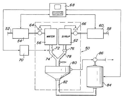
tioner 50 similar to proportioner 14 shown in Figure 1. At
t:he water inlet 52 to proportioner 50 is positioned a flow
meter 54 to determine the mass flow rate of the water
input into the water storage tank 56. Similarly, at the
:>yrup inlet 58, there is a second mass flow meter 60 which
c'ietermines the mass flow rate of the syrup input into the
syrup storage tank 62 of the proportioner 50. Flow meters
54 and 60 are preferably of the type known as a Coriolis
mass flow meter. Coriolis-type mass flow meters are
preferred because of their high accuracy in determining the
mass flow rate and total mass flow without reference to the
temperature or viscosity of the fluid. The size and opera-
tional capabilities of meters 54, 60 will depend upon the
flow rates into the proportioner 50 and the number of
storage tan?cs therein. The flow meters as generally
preferred for use with the present invention are those
manufactured by the K-Flow Corporation of Millville, New
Jersey.
At the inlet side of water storage tank 56 is a
flow control valve 64. The inlet to syrup tank 62 includes
a similar valve 66. These valves 64, 66 are controlled by
a float sensors (not shown) within tanks 56 and 62, respec
tively. A fixed orifice valve 76 is positioned at the
outlet 78 of the syrup tank 62. A micrometer control
valve 72 is located at the outlet 74 of water storage tank
56. Outlets 74 and 78 feed blending tank 80. The outlet
82 of blending tank 80 feeds carbonator 84. The carbonator
84 feeds pump 86 which directs the flow into a bottling or
container filling apparatus (not shown). A float control
(not shown) within the blending tank 80 outputs a signal
which may be utilized downstream of the proportioner 50 by
pump 86 to control the overall flow rate or speed of the
system.
The signals from the flow meters 54, 60 are fed to
a controller 68. Signals from the carbonator 84 are also
fed into controller 68. Controller 68 in turn sends a
7859-2(CIP1).Foreign -5-
/wp/disc#12
~~~~NN
signal to an electronic actuator 70. Actuator 70 is used
to adjust micrometer control valve 72 at the outlet 74 of
water storage tank 56. The actuator 70 controls the throt-
tling or shut off of the valve 72 by a rotary motion based
upon a remote control signal from controller 68. Actuator
70 as contemplated by the present invention may take any
form as desired, such as geared electronic actuator.
Adaptation of the actuator 70 to operate valve 72 may
require a yoke bracket (not shown) or the like to be fit
between the torque output of the actuator and the rotation-
al knob of the micrometer.
Controller 68 may also be used to adjust the
blending performed by variable speed pumps at the outlet of
the proportioner storage tanks. Controller 68 operates
under the following preferred method for adjusting the
proportional blending of a-beverage. Figures 3, 3A, 3B, 4,
and 5 show flow charts for this preferred method.
As particularly shown in Figure 3, at start-up, the
controller 68 reviews certain controls within the system.
First, the controller 68 determines whether or not the mix
or lift pumps (not shown) Within the system are operating.
If the pumps are not operating, the control program will
not continue. If the pumps are operating, the controller
68 proceeds to the next step. There is a initial period at
start-up where the signals from the flow meters 56, 60 and
from other elements in the system may be unstable. A time
delay is input into the system to permit stability to be
achieved prior to making the initial flow meter readings.
Upon exceeding the delay time, controller 68 moves to the
next step. The final preliminary step taken is to deter-
mine whether or not the end run remote switch (not shown)
has been actuated. This end run switch will prevent
further operation of the control program at any time during
the blending operation. Upon completing the start-up
procedure, the signals output from the flow meters 54, 60
7859--2(CIPl).Foreign -6-
/wp/disc#12
~~~~62~
are zeroed to indicate the start of a new batch. Also, the
memory of the previous batch calculations is cleared.
A proportioning and blending system is required at
different times to produce many different types of
beverages under different blending recipes. The appro
priate fixed data related to a particular beverage to be
blended must be identified to properly instruct the con-
troller 68 during further operation. The particular
beverage to be run through the system will be selected at
start-up. This selection actuates the retrieval of data
from stored memory for the particular beverage. There-
after, the syrup and water flow meter signals are read and
the batch is initiated.
As particularly shown in Figure 4, the first
determination made by the controller 68 during a batch run
is whether or not the drink is a sugared drink or whether
or not such is a diet or other non-sugar sweetened drink.
This determination particularly relates to the density of
the syrup.
The first calculation for a sugar-free syrup by the
controller uses the mass flow signal from flow meter 60 to
determine the volumetric flow rate of the syrup. The
volumetric flow of the sugar-free syrup can be determined
from the following equation:
(1) GPMSsf = Ms/(8.333 ~ Dsf)
(GPMSsf = gallons per minute of the sugar-free syrup: Ms =
the mass flow rate of the syrup: arid Dsf = the density of
the sugar-free syrup.) Typically, the density of the
sugar-free syrup can be estimated to be one, i.e. substan-
tially the same as water at 20° C. However, controller 68
may be set to read a different density value for the sugar-
free syrup (Dsf) as determined by the bottler or as set by
the drink recipe owner.
7859-2(CIP1).Foreign -7-
/wp/disc#12
~i~3~~2~
The determination of the volumetric flow rate of a
sugared syrup as a function of the mass flow is also a
function of its density. This density value for a sugared
syrup may be calculated as a function of published brix
values. Curves providing this information are published
by the National Bureau of Standards at Table No. 113. The
brix value for a particular beverage syrup changes during
the blending operation. Therefore, the density for each
particular drink must be calculated. This density value is
calculated by the resultant equation of a least squares
regression on the published curves. This equation is as
follows:
(2) Dsu = Dsu + K(x+~) ~ (DNstd ' Ri)x
(Dsu = density of the sugared syrup; K = a constant corres-
ponding to the least squares calculation; x = the coeffici-
ent value within the calculation; DNstd - the standard
drink number for the particular beverage being prepared;
and Ri - the ideal ratio for mixing the particular syrup
with water.) The calculation using this equation includes
the following constant (K) values:
K(1) _ .9987881
K(2) _ .003715599
K(3) _ .00002321195
K(4) _ .0000002270948
K(b) _ .000000003156378
K(e) _ .00000000001398131
The series of calculations start at x = 5 and Dsu = K(1)
with each subsequent calculation being made for x - 1.
From this density calculation (Dsu), the flow rate
of the sugared syrup can be determined as a function of the
mass flow signal from flow meter 60 by the following equa
tion:
7859-2(CIP1).Foreign -8-
/wp/disc~l2
(3) GPMSsu = Ms/(8.333 ~ Dsu)
In the same manner the output of water flow meter
54 is used to calculate the volumetric flow rate of the
w<~ter as a function of its mass flow. This volumetric flow
rate is determined from the following equation:
(4) GPMW = Mw/(8.333 ~ .998234)
In this equation, a fixed value for the density of the
water at 20°C is used.
The advantage of using Coriolis type mass flow
meters as part of the present invention is due to the
accuracy of the mass flow determination made therefrom.
This mass flow determination is made without reference to
the viscosity or temperature of the fluid. Thus, the
volumetric determinations made by equations (1), (3) and
(4) are essentially free of fluid temperature and viscosity
considerations. Ultimately the accuracy of the blending
control by the present invention is checked against labora-
tory analysis by the bottler. Further, calculations made
by the controller 68 require lab analysis input, such as
the standard drink number (DNstd)~ This data and the
density values used to calculate the volumetric flow for
the water and the syrup (sugar and sugar free) and other
calculations within the system are made on the assumption
that the fluid is at 20°C. Since the signal from the mass
flow meter is not temperature dependent, this assumption
provides accurate results~
The density value for a sugared syrup, as well as
the sugar-free syrup and the mixing water, may also be
determined by utilizing the mass flow meters 54 and 60.
Typically, Coriolis type flow meters are capable of deter-
mining the density of a fluid as well as its mass flow
rate. Thus, the actual brix value of the syrup may be used
to determine the volumetric flow rate into proportioner 50.
7859-2(CIPl).Foreign -9-
/wp/disc#12
2~3~~W
As particularly shorn in Fic3ure 5, the
calculation of the volumetric flow of the sugar-free syrup
uses the mass flow signal from flow meter 60 as well as the
density signal therefrom. Thus, the density of the sugar-
s free syrup (Dsf) in equation (1), above, is an actual
value rather than an assigned value.
The determination of the volumetric flow rate of a
sugared syrup as a function of the mass flow and density
flow readings is somewhat more complicated than for the
sugar free syrup calculation. This calculation generally
involves substituting an actual drink number for the syrup
(DNsyr) within equation (2). The temperature of the
squared syrup becomes a significant factor in determining
of the drink number value. The variation in temperature in
the sugar-free syrup is not considered significant for
purposes of determining a volumetric flow. Thus, the
measured density readings from the densitometer portion of
the Coriolis meter requires correction to 20°C.
The temperature correction factor is calculated by
the resulting equation of a least squares regression
duplicating the curves at National Bureau of Standards
Table No. 120. The resultant equation based upon this
regression is as follows:
(2a) Tcor ° Tcor + ~(xt+~) ' Dmeaxt
(Tcor - temperature correction variable factor; KT - a
constant corresponding to the least squares regression; xt
- the coefficient value within the regression; and Dmea
the measured density value from the flow meter 60.) The
regression for this equation includes the following con
stant (KT) values:
KT(1) - .004109494
KT(z) - .007006943
KT(3) - .00194279
7859-2(CIP1).Foreign -10-
/wp/disc#12
~(~3~~~~
KT(4) - .001908077
KT(b) - .001467323
KT(s) - .0002886857
The calculation starts at xt = 5 and Tcor = KT(1) with each
subsequent calculation being made for xt - 1.
The measured density is corrected to 20°C by the
following equation:
(2b) Dcor = ((Tsyr - 20) ~ Tcor) + Dmea
(Dcor - the corrected value of the measured density and
Tsyr = the actual temperature of the syrup.)
From this corrected density value (Dcor). the
weight percent sugar or brix of the sugared syrup can be
determined by a least fit squares regression of National
Bureau of Standards Table No. 113. This regression equa
tion is as follows:
(2c) DNact = DNact + KD(xd+~) ' Dcorxd
(DNact = the actual syrup brix for the specific syrup; KD =
a constant corresponding to the least squares regression;
and xd = the coefficient value within the regression). The
regression for this equation includes the following con-
stant (KD) values for the density to bricks conversion:
KD(1) - -241.5639
KD(2) - 183.5383
KD(g) _ -16.72519
KD(4) = 289.5726
KD(b) - -293.833
KD(s) = 79.9125
The calculation starts with DNact = KD ( 1 ) and xd = 5 with
each subsequent calculation being made for xd - 1.
7859-2(CTP1).Foreign -11-
/wp/disc#12
2~3~62~
Typically, a correction factor is used by bottlers
for the individual syrup formulas to correct the true brix
value after the solution is diluted to the ideal ratio.
This correction factor can be included into the actual
calculations as follows:
(2d) DNstd = DNact/SYP
(SYP = the syrup correction factor variable.) From this
point the standard drink number (DNstd) can be input into
the original equation (2) so as to continuously calculate
the density of the syrup and the corresponding volumetric
flow rate of the syrup via equation (3).
In the same manner, the output of water flow meter
54 can be used to calculate the volumetric flow rate as a
function of its mass flow and its density flow rate. This
volumetric flow rate is determined from the following
equation:
(4a) GPMW = Mw/(8.33 ~ Dw)
(Dw = the density of the water from the meter 54.)
The result of each of these equations is to provide
a volumetric flow rate which is fixed at a 20°C temperature
factor. As particularly sho~,an in Figure 3A and 3B, from
the volumetric flow rate values a calculated ratio for the
beverage being blended within blending tank 80 may be
determined as well as other aspects of the blending pro
cess.
The ratio of the blend is determined by the follow-
ing equation:
(5) RATIO = GPMW/GPMS
(GPMS = either the calculated volumetric flow of the sugar-
free (GPMSsf) or the sugared (GPMSsu) syrup.)
7859-2(CIP1).Foreign -12-
/wp/disc#12
The blending of a particular beverage is typically
determined as a function of its target drink number. This
target drink number is the proper brix value for the sugar
in the blended beverage as set by the beverage recipe
owner. The bottler must conform to this fixed value in
preparing the beverage. However, in preparing each batch
of syrup (prior to blending), the "standard" drink number
(DNstd) for the syrup batch may not conform to the target
value. A standard drink number for the batch is determined
by the bottler through lab analysis by mixing the syrup
with water in the exact proportion desired by the beverage
owner at a controlled 20°C. The standard and target drink
numbers are typically part of the data read by the con-
troller 68 from stored memory at the start of the batch.
The difference between the target drink number and the
standard drink number for the batch of syrup provides the
bottler with an indication of the original setting of the
micrometer in order to produce a beverage in conformance
with the target value.
Adjustments to the blend during operation of the
proportioner require a determination of the drink number
for the beverage at the time of the adjustment. This
actual drink number can be calculated as a function of the
standard drink number for the syrup batch and the ideal
blend ratio for the particular beverage:
(6) DNcal - ((Ri/~TIO) ~ DNstd) + Boff
(DNcal - calculated drink number and Boff - adjustment
value.) The offset adjustment value may be set by a
bottler or by the beverage recipe owner in order to adjust
the equation in view of past calculations to arrive at the
target. This value may typically be equal to zero (0).
For sugared drinks the calculation of the drink
number can be altered linearize the new standard drink
7859-2(CIP1).Foreign -13-
/wp/disc#12
number calculation. This variation is calculated by the
fallowing equation:
(E'~a) DNcal = ((Log(Ri)/Log(RATIO)) ~ DNstd) + Boff
The same equation can be used to calculate the
drink number for the sugar-free drink. However, the
standard control drink number (DNstd) input by the operator
is used rather than the calculated standard drink of
equation (2d).
The bottler is typically permitted by a beverage
recipe owner to produce the beverage within a certain
percentage range of the target, such as between 100% and
102% of the target drink number. Due to the accuracy of
the present invention in determining the actual drink
number and controlling the blend, a bottler may identify a
set point within this target range. This set point will
likely be the lowest possible consistently obtainable value
in the target range. The calculated drink number (DNcal)
may be compared to the target and set points by the follow-
ing equations:
(7) TGT% _ (DNcal/TGT) ~ 100
(8) SET% _ (DNcal/SET) ~ 100
(TGT% - percentage of the calculated drink number to the
targeted drink number: TGT = the target drink number: SET%
- percentage of the calculated drink number to the set
point value; and SET - the set point for a particular
bottler.) From these percentage values a determination
can be made as to whether of or not an adjustment of the
blend is required. Adjustment will be discussed in further
detail below.
The volumetric flow rate determinations of equa-
tions (1), (3) and (4) may be used to calculate the total
7859-2(CIP1).Foreign -14-
/wp/disc#12
~O~~i~~'
flow rate out of the proportioner 50 by the following
equation:
(9) GPMtot = GPMS + GPMW
Further, the total flow for the particular batch at any
particular time can be determined from the total mass flow
signal received from the flow meters 54, 60:
(9a) FLOWtot ° MStot/(8.333 ~ Dsyr)
+ MWtot/(8.333 ~ .998)
(MStot - the total mass of the syrup; MWtot = the total
mass of the water; and Dsyr = the density of the syrup-
Dsf for sugar-free syrup or.:Dsu for sugared syrup.)
One variation in the blending of a beverage is the
solubility of the C02 input into the beverage by the
carbonator 84. This variable is determined as a function
of the temperature and pressure within the carbonator 84.
Published curves for these determinations in graph format
are produced ,by the American Bottling Association. This
variable is typically reported in volumes of C02.
A least squares method may again be utilized to
calculate the temperature factor of the carbonation as a
function of the changing conditions in carbonator 84. The
least squares regression for this temperature component is
as follows:
(10) Tcoz = TcoZ + KC(XC+~) ~ Tcarbxc
(Tcoa - the temperature coefficient for carbonator; KC =
the coefficient value within the calculation; xc - the
position within the regression; and Tcarb = the temperature
in °F in the carbonator.) The constants within this
regression are as follows:
7859-2(CrPi).Foreign -15-
/wp/disc~l2
2(~3~~~~
KC(1) - .3529254
KC(2) - .008671118
KC(g) - .000007131652
KC(4) - .000002720279
KC(6) - .00000003849611
KC(g) - .000000000177644
The calculation starts at xc = 5 and Tcoz = KC(1) with each
subsequent calculation being made for xc - 1.
An additional factor must be determined prior to
calculating the volumes of COZ added to the beverage. This
factor is a result of the pressure in the carbonator 84
and can be determined by the following equation:
(11) Pfac = (Pco2/13.7) + .075
(Pco2 - the pressure within the carbonator system.) The
constant values within this equation 11 have been deter-
mined from the same published sources of the American
Bottling Association as for equation (10).
From the determination of the temperature
coefficient and the pressure factor in the carbonator 84,
the volumes percent of carbonation can be determined as
follows:
( 12 ) VOLcoa ° ( Pfac/Tcoz ) '~' Cof f
(Coff = offset adjustment value.) Typically, the volumes
of C02 is determined by a shake test outside of the
carbonator. The present calculations are being performed
in line. Therefore, the readings made by in line sensors
may not provide an accurate value. This determination may
be adjusted (Coff) to provide a value that is within the
desired specifications of the bottler. The offset value is
provided so as to account for the standard variations in
the calculation from the normal mode of testing.
7859-2(CIP1).Foreign -16-
/wp/disc#12
~036~2N
The total volumetric flow determination (FLOWTot)
can be used to predict the number of cases which should be
produced by a particular run.
(:L3) CASEproj _ (FLOWtot ~ 128)/CONTvol/CASEsize
(CONTvol - the volume in each particular container and
CASEsize - the number of containers to be input into a
case.)
The controller 68 may be set to receive a pulse
signal for each bottle or container passing through the
bottling apparatus. From this pulse count, the actual
total number of cases produced is determined by the
following equation:
(14) CASETot = P / CASEsize
(P = the number of pulses received from the bottler.)
An efficiency estimate may be made by using the
volumetric calculations for the projected case total and
comparing this value to the actual number of cases which
have been produced:
(15) CASElast = CASEproj - CASETot
Also, an efficiency determination for the entire
system can be made by evaluating the run time and the
maximum obtainable cases per minute. This efficiency
calculation is as follows:
(16) EFF = ((P/Trun)/CPM) ~ 100
(Trun = the time of the batch run and CPM = the determined
maximum cases per minute value seen during the particular
batch run.) The maximum cases per minute during the run
7859-2(CIP1).Foreign -17-
/wp/disc#12
21~~G~2~
and the comparison to the overall output of the run are
values which are usually desired by the bottler.
All values calculated can be displayed on a screen
for observation during the run. These calculated values
can be averaged over a number of cycles by the controller
68 and may also be displayed as a function of the average
over a specific period of time such as 1 minute. The time
averages can also be charted on a graph and displayed
accordingly.
The controller 68 may be used to evaluate various
other operating functions of the system. By connecting the
sensors within the system to the controller 68, certain
alarm signals may be defined to determine whether a criti-
cal error exists in the system. with a critical alarm, an
acknowledge signal may be required in order to continue
the operation or calculations of the system.
From the calculated values, a determination can be
made of the adjustment required by the valve 72 in order
for the proportioner 50 to blend the beverage in line with
the set point of the bottler. The first determination is
the variation of the calculated drink number from the set
point:
(17) ERROR = DNcal - SET
If there is an variation between these two values, an
adjustment is required. From the error value a control
signal may be directed to actuator 70 for appropriate
adjustment of the micrometer valve 72 to bring the blended
beverage into line with the set point and, thus, the recipe
owner's target. This adjustment may be determined by the
following equation:
(18) Madj = ((ERROR ~ GAIN) + (ERROR ~ TE/TK))/100
7859-2(CIP1).Foreign -18-
/wp/disc#12
~t~3~~~
(GAIN = a multiplication factor for the ERROR signal; TK =
an integral time constant in repeats per minute; and TE =
the elapsed time from the last adjustment.) The value for
the integral time constant is discretionary and is con-
s templated to be set as part of the programing of controller
68, rather than being set by the bottler. Therefore, this
value would not be changed after installation.
As can be seen from the equations, a calculated
drink number (DNcal) which is greater than the set point
(SET) will result in a positive error (ERROR) signal. This
positive error will be converted into a positive value for
the adjustment (Madj) of valve 72. This positive value
will increase the amount of water within the blend and
decrease the resulting drink number (e. g., for a sugared
beverage, reduces the brix value for the sugar in the
blended beverage). Thus, the next calculation made for the
error (ERROR) signal will be decreased. If this newly
calculated drink number is not equal to the set point and,
thus, the error signal is not equal to zero, the micrometer
will be adjusted again. A calculated drink number that is
less than the set point will approach a zero error value in
the same manner, but from the opposite direction.
The micrometer adjustment calculation of equation
(18) would produce a change in the setting of the valve 72.
The setting value for a micrometer-type valve is typically
expressed in mils over the total length of the valve
movement. A calibration factor may be required to direct
the actuator 70 to adjust the micrometer within the proper
proportions. Further, a different calibration may be
required to provide a readout of the mil position of the
micrometer in the bottler's normal units.
Upon initial start-up of the system, the bottler
would manually or through the controller 68 open the valve
72 to a recommended value for the drink specification.
Thereafter, it is also possible to manually adjust this
valve for any additional changes other than those made by
7859-2(CIP1).Foreign -19-
/wp/disc#12
the actuator 70 in response to the control signals from
controller 68. The most common error (ERROR) will be the
result of the start-up position of the valve 72. The
setting of this valve 72 at start-up is typically an
estimate. Once the blended beverage has been adjusted to
the target range, the only changes that would be required
to maintain the blend within that range and at the set
paint would be initiated by the actuator 70 via the cal-
culations and control signals of controller 68.
The adjustment of the valve 72 by controller 68
preferably includes a range limit. This range would
prevent the controller from adjusting the valve 72 at too
great a variation without further authorization from the
bottler. It is contemplated that a plus or minus 2%
variation in the micrometer setting would be a sufficient
limit for this purpose. If a greater value were calculated
by the controller 68, such may be the result of an unusual
error within the system. An audible alarm would then
initiate a warning to the bottler that a significant change
has occurred within the system. The bottler will be
required to cancel the calculated result or approve the
change and initiate a new 2% control limit. This scheme
ensures a quality control with limitations. This will
confirm that the variations are a normal fluctuation within
the system rather than a miscalculation or unusual error.
If the user does not agree with the value change, the
product will not deviate off specification without further
proof that such is required.
The system in accordance with the present invention
has been found to be highly accurate in controlling the
operation of the proportioner and for maintaining the blend
within the standard set by the beverage owner. It is
contemplated that the present invention can be adapted to
existing bottling systems throughout bottlers within the
United States. The present invention will incorporate into
the existing bottling system a highly accurate means for
7859-2(CTP1).Foreign -20-
/wp/disc#12
~~3~~~
automatically controlling the proportional blending of the
beverage. The ultimate accuracy of the control initiated
by the present invention may continue to be determined as a
function of an analyzer which is either downstream in the
system or which is performed in the lab. However, by the
application of the present invention into the existing
bottling plant, it is contemplated that the need for
disposal of already blended beverage which is not made in
accordance with the requirements of the recipe owner will
be eliminated after achieving a consistent setting for the
control valve in the proportioner.
The present invention may be embodied in other
specific forms without departing from the spirit or essen-
tial attributes thereof and, accordingly, reference should
be made to the appended claims, rather than to the fore-
going specification, as indicating the scope of the inven-
tion.
7859-2(CIP1).Foreign -21-
/wp/disc#12