Note: Descriptions are shown in the official language in which they were submitted.
--1--
20~6654
TITLE
PROCESS AND APPARATUS FOR ~lN~ NOX
ONS FROM rQMRu~TIoN DEVICES
BACKGROUND OF THE INVENTION
Field of the Invention
The present invention relates to a process of
reducing nitrogen oxide emissions from combustion
devices.
Description of the Prior Art
In the comkustion of fuels with fixed nitrogen
such as coal, oxygen from the air may combine with the
fixed nitrogen to produce nitrogen oxide NO or nitrogen
dioxide NO2 which are collectively called nitrogen oxides
or NOx. At sufficiently high temperatures, oxygen reacts
with atmospheric nitrogen to form nitrogen oxides. So,
even fuels that have no fixed nitrogen produce nitrogen
oxides when fired with excess air at sufficiently high
temperatures. Production of nitrogen oxides is regarded
as undesirable. There are numerous government
regulations which limit the amount of nitrogen oxides
which may be emitted from combustion devices.
Furthermore, the presence of nitrogen oxides in a flue
gas causes the condensate formed from the gases to become
more corrosive and acidic. Consequently, there is a need
-2- 2036654
for apparatus and processes which reduce the nitrogen
oxide emissions in flue gas.
Numerous attempts have been made to develop
apparatus and processes which reduce the nitrogen oxide
emissions from combustion devices. Among the attempts
are burner redesigns such as dual register low-NOx
burners, staged air combustion, flue gas recirculation,
reduced air preheat, and increased furnace size. All of
these techniques have had some success, but all suffer
from some limitations and they are expensive. Currently
more stringent regulations are forcing the development of
new processes for NOx control.
One such new approach is a process known as in-
furnace NOx reduction, reburning, or fuel staging. In
reburning, coal, oil, or gas is injected above the normal
flame zone to form a fuel-rich zone. In this zone, part
of the nitrogen oxides are reduced to ammonia-like and
cyanide-like fragments which are then oxidized to form N2
and nitrogen oxide.
Several problems occur when this process is
used. First, coal may be an inefficient reburn fuel
because of its high fixed-nitrogen composition. The
fixed nitrogen introduced at this location in the furnace
will have less chance of being converted to N2, and
therefor have a higher chance of ending up as nitrogen
oxides and may, depending on the nitrogen oxide
203665~
concentration of the flue gas, increase the emissions of
nitrogen oxides.
Furthermore, the fuel must be injected with a
sufficient vo~ume of gas. If air is used as this gas,
there must be enough fuel to consume the oxygen in the
flue gas and air, and to supply an excess of fuel so
reducing conditions exist. This increases the amount of
fuel which must be used as reburn fuel. Furthermore, the
necessity of using carrier air re~uires extensive duct
work in the upper part of the furnace.
Additionally, the reburn fuel must be injected
well above the primary combustion zone of the furnace so
that it will not interfere with the reactions taking
place therein. However, this fuel must be made to burn
out completely without leaving a large amount of unburned
carbon. To do this, the fuel must be injected in a very
hot region of the furnace some distance from the furnace
exit. The exit temperature of the furnace must be
limited in order to preserve the heat exchanger's
surface. Therefore, a tall furnace is required to
complete this second stage process.
Moreover, the fuel must be injected in
quantities sufficient to make the upper furnace zone
fuel-rich. This excess fuel ultimately requires more air
in order to be completely combusted. Thus, air must be
injected above the zone of reburn fuel injection. This
-
-4- 2036654
arrangement requires even more duct work and furnace
volume. This excess air must consume the reburn fuel
before the gases reach the furnace entrance.
Finally, most coal furnaces which are now in
operation are not designed to accommodate the prior art
methods. Major modifications such as the provision of
extensive duct work and the addition of a second stage to
the process are required to utilize the prior art method.
Such retrofitting is expensive. Consequently, there is a
need for a combustion process requiring little additional
apparatus which will reduce nitrogen oxide emissions in
flue gas and which can be readily used in existing
furnaces.
SUMMARY OF THE INVENTION
In accordance with the present invention, there
is provided an improved process for reducing NOX content
in combustion device flue gas. A combustible gas or
volatile liquid such as natural gas or hexane is premixed
with the combustion air in an amount below the lower
combustible limit of the air/fuel mixture. This fuel
burns as it mixes with hot combustion products in the
furnace.
We prefer that the fuel which is mixed with the
combustion air have little or no fixed nitrogen. As this
fuel burns, it will not produce nitrogen oxides by the
~5~ 2036654
reaction between oxygen and fixed nitrogen. Part of the
air will mix with partially cooled but still relatively
hot combustion products and the fuel carried in with the
air will burn as this mixing occurs. This combustion
will be at relatively low temperature, that is, much
below 3000,F, where very little nitrogen oxides can form
from nitrogen in the air and oxygen in the air. In
addition, the fuel in the air when it mixes late into the
combustion process will burn producing radicals such as
CH2, CH, CH3, and OH, which will react with NO to produce
N2 and reduced nitrogen species which will react further
with NO to form N2. The fuel can be added to the
combustion air before or after the forced draft fan, or
before the burner if there is no forced draft fan.
Alternatively, air which is contaminated with combustible
materials can be used as the combustion air.
Because of the simplicity of our process, it is
well suited for retrofitting existing boilers, furnaces,
heaters, kilns and other combustion devices. Our process
uses air into which a small amount of fuel has been mixed
in order to operate the combustion device. The fuel is
introduced into the air as simply as possible. Part of
the fuel, so introduced, will be burned at low
temperatures resulting in low nitrogen oxide emissions.
Other advantages of the invention will become apparent
from the description of the preferred embodiments.
203665~
BRIEF DESCRIPTION OF THE DRAWINGS
Figure 1 is a schematic of a furnace arrangement
having burners, which arrangement is suitable for the
practice of our invention.
Figure 2 is a side view partially in section of
an overfired air throat suitable for the furnace of
Figure 1.
Figure 3 is a side view partially in section of
a burner which is suitable for the furnace of Figure 1.
Figure 4 is a schematic of a furnace arrangement
having a moving grate, which arrangement is satisfactory
for the practice of our invention.
DESCRIPTION OF A PREFERRED EMBODIMENT
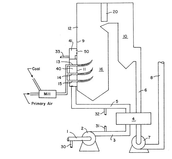
As shown in Figure 1 of the drawings, our new
process for reducing the nitrogen oxide content of gases
in flues 10, 6, and/or 8, can be readily practiced in a
retrofitted existing furnace 12. The furnace 12 can be
one which uses coal that may be milled and combined with
primary air or other fuel, although it is shown here
using coal. The furnace may be designed to produce steam
or heat other materials, but here it is shown as part of
a steam generation system. The fuel enters the furnace
12 by way of fuel entries 13, 14 and 15, which are
located in the lower portion of the furnace 12. It burns
in large part in the primary combustion zone 16 which
--7--
2036654
typically has temperatures which can exceed 3000lF. The
combustion products produced in the primary combustion
zone 16 are cooled by the furnace walls 9 and then by the
convective section or heat exchanger 20. They progress
through duct sections 10 and 6 into the air heater 4,
where they are cooled further by the incoming air. They
then proceed into the induced draft fan 7 which expels
them into the stack 8, and from there into the
atmosphere. The flue gas has a temperature range of
2100,F to 2400lF when it exits the furnace near the heat
exchanger 20. Accordingly, at any point above the
primary flame zone 16 the temperature is lower than it is
in that zone. During the combustion of the fuel, some of
the fixed nitrogen reacts with oxygen to form nitrogen
oxides. Nitrogen oxides are also formed from atmospheric
nitrogen and oxygen. During the process, secondary air
is taken in by the forced draft fan 2 and conveyed by
duct work 3 into the air heater 4 where it is heated and
flows through duct work 5 into the secondary air plenum
40, which supplies secondary air to the burners 13, 14
and 15 on furnace wall 11. Fan 2 may also supply
secondary air by an additional duct or plenum 41 to
overfire air ports 50 which are provided in some furnaces
near the burners. As shown in Figure 2, the overfire air
port 50 may have a throat 51. Primary air which may be
extracted from the heated secondary air source or other
-8- 2036654
sources, and coal are fed to a mill where the coal is
pulverized and blown into the burners. Overfire air
ports 50 are sometimes used to add additional air in
order to complete combustion beyond the burners if they
operate with near stoichiometric or even slightly fuel-
rich mixtures. The purpose of such a procedure is to
reduce the nitrogen oxide emissions.
In other furnaces, secondary air is introduced
around the primary air and fuel stream as shown in Figure
3. In this arrangement, a pipe 52 which carries the
primary air and fuel stream, is positioned within housing
54 which carries secondary air. Commonly, a throat 55 is
provided at the entry of the housing 54 through the
adjacent furnace wall 11. A spreader 53 may be provided
on the entry of pipe 52. Frequently, the entire
structure in Figure 3 is called a burner.
We provide fuel addition apparatus 30, 31, 32 or
33 which may be pipes, nozzles, orifices, or injectors
with static mi xi ~g devices as needed. The fuel addition
apparatus may be positioned at the secondary air intake
as is pipe 30, after the forced draft fan as is pipe 31,
after the air heater 32, or in the duct to overfire air
plenum 41 as is pipe 33. These devices introduce natural
gas or other gaseous or volatile fuels having little or
no fixed nitrogen into the secondary air stream so that
those fuels are well mixed with the air before they enter
-
-9- 2036654
the furnace. The resulting fuel/air mixture does not
have enough fuel to burn at ambient conditions. As it
mixes into flames in the furnace or with hot gases from
the primary flames, the fuel in the air burns. Much of
the fuel burns at temperatures well below the peak flame
temperature.
Much of the fuel burns at low temperature.
Almost all of the fuel which enters through overfire air
ports 50 will burn at low temperature. This combustion
will reduce the NOx by a number of mechanisms, plus the
combustion of this fuel heats the overfire air and so
assists in mixing it into the combustion products.
An alternative method of introducing the
air/fuel mixture is to start with an air stream which is
naturally or industrially contAminAted with a fuel. This
mixture can be introduced at air intake 30. An example
of this is coal mine ventilation air which contains
methane.
Fuels desirable in addition to natural gas are
hydrogen, petroleum products and compounds of the form
CXHy or CyHyOz and mixtures of these.
These fuels as they burn at low temperatures,
form very little nitrogen oxide. In addition, their
combustion produces fuel radicals such as CH, CH2, CH3,
and others which react rapidly with previously formed
nitrogen oxide to reduce it to near its low equilibrium
2036654
--10--
values which exist at those low temperatures. The
radicals react with nitrogen oxide to form nitrogen-like,
ammonia-like, and cyanide-like compounds:
(1) CH3 + NOx --> N2 + NHi
These reduced nitrogen compounds react with additional
nitrogen oxide to form nitrogen by the following
reactions:
(2) NHi + NO --> + HiO
(3) HjCN + NO --> N2 + HjCO
These equations characterize the process, but do not show
all the reactions, pathways and intermediate species
which may occur.
We may add the fuel to the air in various
locations. We prefer to keep the concentration below the
lower explosive limit of the air/fuel mixture. This
lower explosive limit will be the upper limit for the
heated air after it leaves the air heater. However, as
it is heated further in the furnace, it will ignite and
burn. Most of this further heating will be by m; x; ng
with combustion products.
If the furnace uses overfire air ports 50, it
may be desirable to add the fuel only to the air going to
the overfire air ports as indicated by line 33. All of
the fuel will burn at low temperatures. The mAX;~um NOX
-11- 203665~
reduction per unit of fuel mixed with air will be
achieved.
As we have mentioned, we also use the process of
this invention to consume air which has been contaminated
with fuel. Such air may be mine ventilation air, paint
booth ventilation air, print drying air, solvent drying
air and other air which has been cont~mi~ted with
combustible materials. Such use reduces nitrogen oxide
emissions, saves energy, reduces hydrocarbon emissions,
and prevents hydrocarbons emissions from becoming part of
the greenhouse effect problem. If such waste air/fuel
streams are directed to overfire air ports or burner out
of service registers, the nitrogen oxide emissions are
even further reduced.
The use of fuel mixed with air will reduce
nitrogen oxides in the flue gas in three ways. First,
the fuel contains little if any fixed nitrogen.
Consequently, unlike a fuel cont~ining fixed nitrogen,
the combustion of this fuel creates very little
additional nitrogen oxide. Second, since at least part
of the fuel which has been mixed with air will burn at a
lower temperature, very little nitrogen oxide will form.
Third, natural gas also reduces the amount of nitrogen
oxides in the flue gas directly by the chemical reactions
set forth in e~uations (1), (2), and (3) above.
-12- 20366~4
In addition to providing a large reduction in
the nitrogen oxide content of flue gas, our invention is
cost-effective as a retrofit to existing furnaces,
boilers, kilns, and heaters.
Our process is also useful for stoker fired
boilers, one of which is illustrated in Figure 4. The
process can be used on any type of stoker. This
particular stoker is a spreader stoker, which has a
rotary-spreader 123 to throw the coal onto the grate 104.
A feeder 122 delivers the coal from a bunker 150 to the
rotary spreader 123. Air is taken into the ID fan 102
through the inlet duct 101, where it passes to the
undergrate plenum 103. From the plenum 103 it passes
through the grate 104 and burns the coal on the grate.
Some of the coal also burns above the grate. The air,
combustion products, volatile hydrocarbons from the coal,
and partially burned products progress to a higher level
in furnace 105 where combustion continues. To improve
the combustion, overfire air is often added to stoker
furnaces to assist in the mixing. The overfire air is
supplied by overfire air fans 120 or duct work 130 from
the primary air fan and it flows to headers 121 and from
the headers it flows through multiple pipes into the
furnace m; X; ng the gases and completing the combustion.
From the upper furnace the flue gas flows through to
convective pass 106 to the economizer 107, the ash hopper
-
2036654
-13-
108, into the dust collector 109, into the induced draft
fan 111 and finally into the stack 112. In the stack,
the flue gas will contain nitrogen oxides. Stokers may
or may not have air heaters and either or both of the
induced draft or induced draft fans may not be used.
In order to implement our invention on stokers,
we will add gaseous fuel or volatile fuel through pipes
143 or 144 to the air before it enters the induced draft
fan 102 or the overfire air fan 120, to the air after it
leaves those fans 102 or 120, or to the air in ducts 121
leading to the overfire air headers. Alternatively, air
cont~m;n~ted with fuel can be introduced in place of all
or part of the usual undergrate or overfire air.
While we have shown and described a present
preferred embodiment of the invention and have
illustrated a present preferred method of practicing the
same, it is to be distinctly understood that the
invention is not limited thereto, but may be otherwise
variously embodied and practiced within the scope of the
following claims.