Note: Descriptions are shown in the official language in which they were submitted.
Patent 13DV-9594
2~3~2~
~YPASS V~LVE SYST~M
This invention was made with Government
support under Contract F33657-83-C-0281 awarded by the
Department of the ~ir Foece. The Government has certain
rights in this invention.
Cross-reference to Related Application
This application is related to application
serial n~mber _ , (docket number
13DV-10393) filed concurrently herewith and entitled
nBypass Valve Doorn.
Technical Field
The present invention relates generally to
gas turbine engines, and, more specifically, to an
improved bypass valve system.
Backqround Art
A conventional variable cycle gas turbofan
engine includes a core engine driving a fan, and a
bypass duct surrounding the core engine which is in flow
communicatlon with the fan. A conventional bypass valYe
is disposed at an upstream, inlet end of the b~pass duct
and is positionable in a closed position which
substantially blocks flow from the fan into the b~pass
duct under certain conditions in the flight envelope of
an aircraft being powered by the engine while allowing
flow from the fan to be channeled into the core engine.
The bypass valve is also positionable in an open
position which allows sub~tantially unobstructed flow
from the fan into the bypass duct for bypassing a
Patent 13D~-9594
~3~2~
-2-
portion of the fan air around the core en~ine while
allowing the remaining portion of the fan air to be
channeled through the core en~ine during operation of
the aircraft at other conditions in the flight envelope.
Conventional bypass valve assemblies are
relatively complex and are controlled in accordance with
predetermined schedules corresponding to operation in
the flight envelope of the aircraft. An exemplary
conventional bypass valve assembly includes an annular
ring valve which is translatable to open and close an
annular inlet to the bypass duct. Conventional linkages
and servovalves are used to translate the valve and are
operatively connected to the control system of the
engine for being responsive to the predetermined
schedules cont~ined in the control system for opening
and closing the bypass valve at various conditions in
the flight envelope.
In the open position, the bypass valve must
provide for substantially unobstructed flow into the
bypass duct for reducing or minimiziny pressure losses
therefrom which would decrease performance of the engine
and reduce the cooling ability of the bypass air
channeled in the bypass duct. The bypass air is
typically used to improve cruise SFC and to cool
downstream structures in the engine, such as, for
example, a conventional augmentor and ~ariable area
exhaust nozzle, and any pressure losses due to the
bypass duct would have to be accommodated, t~pically by
increasing pressure in the bypass duct which decreases
engine performance. Furthermore, the bypass valve must
also provide for substantially unobstructed flow and
smooth transition into the bypass duct to prevent or
minimize any backpressure on the fan which would
undesirably reduce stall margin of the fan.
The bypass valve in the form o a mode
Patent 13DV-9594
~ ~ $3 ~
selector valve is typically positioned between a fully
open position and a fully closed position for double or
single bypass operation of an exemplary double bypass
engine. In alternate embodiments, the bypass valve may
additionally be disposed at intermediate positions
therebetween, as required by particular aircraft engine
applications. In this way, the bypass ratio
conventionally represented by the total engine airflow
divided by the core engine airflow may be varied during
operation of the aircraft engine.
A significant problem associated with the
variable geometry required for positioning bypass valves
is the availability of mounting space, and
correspondingly, the amount of allowable weight for the
bypass valve system. Typically, little axial and radial
envelope is available in conventional augmented turbofan
engines due to the close proximity between the fan,
compressor rotors, and external gear box for the bypass
valve system. Without available space, the engine must
be redesigned for having a larser diameter and longer
axial length for accommodating the required bypass valve
system. Increased radial and axial size of a gas
turbine engine and the corresponding increase in weight,
is undesirable since it leads to additional weight and
penalty losses for the overall engine.
Furthermore, conventional bypass valve
systems typically require rigging, or adjustments at
assembly to ensure coordinated movement and full travel
of parts. Rigging increases assembly time and costs
associated therewith.
Obiects of the Invention
Accordingly, one object of the present
invention is to provide a new and improved bypass valve
Patent 13DY-9594
~ ~ 3 ~
~ystem.
Another object of the present invention is to
provide a bypass Yalve system which is relatively
compact and lightweight.
Another object of the present invention is to
provide a bypass valve system having an improved
actuation system requiring relatively few part
Another object of the present invention is to
provide a bypass valve system having an actuating system
requiring relatively little space for positioning a
bypass valve between opened and closed positionsO
Another object of the present invention is to
provide a bypass valve system includin~ an improved
bypass valve door which is positionable in an open
position for providing a smooth fluid boundary with
minimal aerodynamic losses therefrom.
Another object of the present invention is to
provide a bypass valve assembly having reduced, or
eliminated r ig g ing .
Disclosure of Invention
A bypass valve system includes an annular
frame defining a cavity and having an intermediate
casing with an annular opening including a plurality of
bypass valve doors disposed thereinc ~n annular
actuation ring is disposed in the frame cavity and a
plurality of space links are pivotally connected between
the ring and the bypa~s valve doors. Each of the space
links includes a longitudinal axis and means are
provided for rota~ing the actuation ring between a first
position wherein each link longitudinal axis bas a first
inclination angle and the doors are in a first position,
and a ring second position wherein the space link
longitudinal axi~ has a second inclination angle less
Patent 13DV-9594
2 ~
--5--
than the first inclinatlon angle so that the links pivot
the doors about a doox first end to position the door in
a door second position.
Brief Descri~tion of ~rawings
The novel features believed characteristic of
the inven~ion are set forth and differentiated in the
claims. The inven~ion, in accordance with preferred and
exemplary embodiments, together with further ob~ects and
advantages thereof, is more particularly described in
the following detailed description taken in conjunction
with the accompanying drawing in which:
Figure 1 is a schematic representation of an
augmented, variable cycle, gas turbine turbofan engine
for powering an aircraft which includes a bypass valve
system in accordance with one embodiment of the present
invention.
Figure 2 is a perspective schematic
representation of a portion of the bypass valve system
illustrated in Figure l.
Figure 3 is an upstream facingO perspective
view of a por~ion of the bypass valve system illustrated
in Figure 2 taken along line 3-3 illustrating bypass
valve doors in an open position.
Figure 4 is a view of the portion of the
bypass valve system illustrated in Figure 3 showing the
bypass valve doors in a closed position.
Figure 5 is a transverse se~tional view of a
portion of the bypass valve system illustrated in Figure
2 showing means for actuating the bypass valve doors
therein.
Figure 6 is a transverse sectional view of
the bypass valve system illustrated in Figure 4 taken
along the line 6-6.
Patent 13DV-9s94
3~2~
Figure 7 i6 a top view of a portion of the
bypass valve system illustrated in Figure 3 taken along
line 7-7 illustrating the bypass valve doors in the open
position~
Figure 8 is a top view of the b~pass valve
system illustrated in Figure 4, similar to the view
illustrated in Figure 7, showing the bypass valve doors
in the closed position.
Figure 9 is a transverse sectional view of
the actuation r ing used in the bypass valve system
illustrated in Figure 7 taken along line 9-9.
Figure 10 is a top, partly sectional view of
one of the space links used in the bypass valve system
illustrated for example in Figures 3 and 4.
Figure 11 is a transverse sectional view of
the space link illustrated in Figure 10 taken along the
plane defined by line 11-11,
Figure 12 is a transverse sectional view of
the space link illustrated in Figure 11 shown in a
compressed position.
Figure 13 is a perspective view of one of the
bypass valve doors used in the bypass valve system
illustrated for example in Figures 3 and 4~ along with a
complementary portion of the frame.
Figure 14 is a partly schematic, top view of
one of the bypass valve doors similar to the view
illustrated in Figure 7, for example, with the space
link being removed for clarity~
Figure 15 is a com~ound, transverse,
sectional view of an upstream end portion of one of the
bypass valve doors and the complementary frame taken
along line 15-15 in Figure 13.
Figure 16 is a transverse sectional view of a
bypass valve system in accordance with a second
embodiment of the present invention.
-~ Patent 13DV-9594
2~3~2~
~7--
Figure 17 is a top view of a portion of the
bypas~ valve system illustrated in Figure 16 taken along
line 17-17.
Figure 18 is a perspective view of a portion
of the second embodiment of the bypass valve system
showing a second embodiment of the actuation ring joined
to a respective bypass valve door.
Mode(s) For CarrYinq Out the Invention
Illustrated in Figure l is a schematic
representation of an exemplary variable cycle gas
turbine turbofan engine lO for powering an aircraft in a
flight envelope including subsonic and supersonic speeds
at various altitudes. The engine lO includes an annular
inlet 12 for receiving ambient air 14 followed in turn
by a conventional forward fan 16, aft fan 18y or low
pressure compressor, high pre~sure compressor (HPC) 20~
combustor 22, high pressure turbine (HPT) 24, and low
pressure turbine (LPT) 26. The HPT 24 powers both the
aft fan 18 and the HPC 20 through a conventional first
shaft 28. The LPT 26 powers the forward fan 16 by a
conventional second shaft 30.
The engine lO further includes an outer
casing 32 which is spaced from an inner casing 34 to
define a conventional bypass duct 3~ therebetween.
Extending downstream from the outer casing 32 and the
LPT 26 is a conventional afterburner, or augmentor, 38
which includes a conventional liner 40 surrounded by a
conventional annular afterburner duct 42.
The afterburner duct 42 is in flow
communication with the bypass duct 36 and a conventional
mixer 44 is disposed therebetween for mixing a portion
of bypass air 4~ channeled through the bypass duct 36
with combustion discharge gases 48 discharged from the
Patent 13DV-9594
-8~
LPT 26, which are channeled into the aPterburner 38 and
discharged through a conventional variable area nozzle
50 disposed at the downstream end of the afterburner 38~
In this exemplary embodiment, the engine 10
S is a double bypass engine including an optional~
conventional valve 52 disposed in the inner casing 34
between the aft fan 18 and the HPC 20 or channeling
into the bypass duct 36 a portion of the air 14 which
flows through the aft fan 18 during certain operation of
the engine. The valve 52 may be conventionally open or
closed as desired or, in another embodiment, the valve
52 may be omitted which allows continuous flow o~ a
portion of the air 14 from between the aft fan 18 and
the HPC 20 into the bxpass duct 36.
The engine 10 is conventional except for a
b~pass valve system 54 in accordance with a preferred,
exemplary embodiment of the invention disposed between
the orward fan 16 and the aft fan 18, Illustrated in
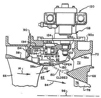
Figure 2 is the bypass valve ~ystem 54 shown in more
particularityO The system 54 includes an annular fan
frame 56 having an intermediate casing 58 and an inner
casing 60 spaced radially inwardly from the inner casing
58 to define a first channel 62 for channeling the air
14. The forward fan 16 includes a plurality of
~5 conventional fan blades 64 which are conventionally
connected to the second shaft 30, and a plurality of
conventional fan outlet guide vanes (OGVs) 66 which are
disposed in the first channel 62 for supporting the
inner casing 60 to the intermediate casing 58 and for
channeling the air 14.
A conventonal annular flow splitter 68 is
conventionally fixedly disposed between the intermediate
and inner ca ings S8 and 60 by a plurality of
circumferentially spaced struts 70 extending between the
intermediate casing 58 and the splitter 68 which ca~ing
Patent 13DV-9594
_g_
and splitter deflne a second flow channel 72, or inlet
to the bypas~ duct 36. The splitter 68 is
conventionally connected to the inner caslng 60 by a
plurality of circumferentially spaced conventional inlet
guide vanes (IGVs) 74 which define therebetween a third
~low channel 76, or inlet to the core engine. The aft
fan 18 of the core engine includes the IGVs 74 and a
plurality of conventional, circumferentially spaced
blades 78 conventionally operatively connected to the
first shaft 28. The splitter 68 includes a leading edge
80 which splits the air 14 into a bypas~ airflow 82
which is channeled into the second channel 72, and a
core airflow 84 which is channeled into the third
channel 76.
The assembly 54 further includes an annular
opening 8S in the intermediate casing 58 facing the
splitter 68. Disposed in the annular opening 86 is a
plurality of circumferentially juxtaposed bypass valve
doors 88. In an exemplary embodiment, there are 12
doors 88 disposed over the 360 circumferential extent
of the opening 86~
The frame 56 further includes an outer casing
90 spaced radially outwardly from the intermediate
casing 58 to define a cavity 92 therebetween. An
annular actuation ring 94 is disposed in the cavity 92
coaxially about a longitudinal centerline axis 96 of the
frame 56, and of the engine 10. ~s illustrated in
Figure 3, each of the doors 88 includes an outer surface
98 and an upstream, first end 100 pivotally connected to
the frame 56. More specifically, formed integrally to
the door outer surface 98 at the up~tream end 100 is a
pair of circumferentially spaced clevises 102, each of
which i8 pivotally connected to a hinye support 104~ for
example by a bolt extending through the hinge 6upport
and the clevis J with the hinge support being f ixedly
Patent 13DV-9594
3 ~ ~
--10~
connected to the intermediate casing 58. Conventional
composite bushings, such as for example Avimid N
bushings available from Tribon Bearing Company, may be
disposed between tAe bolts and the complementary
apertures in the clevises 102 and the hinge support 104
for reducing friction as the door 88 rotates relative to
the hinge support 104. A straight hinge axis 106
extends through the centers o~ the bolts in the clevises
102 for defining an axis about which the doors 88 are
pivotable. Each of the doors 88 further includes a
downstream, or second end 108.
The doors 88 are positionable in a first, or
open position, as illustrated in solid line in Figure 5,
which is generally parallel to the intermediate casing
58 to allow subs~antially unobstructed flow of the
bypass airflow 82 into and through the second channel
72. The doors 88 a~e also positionable in a second, or
closed position, as illustrated in dashed line in Figure
5, wherein the door do~nstream end 108 is disposed
adjacent to the splitter 68 for substantially blocking
the bypass airflow 82 from the first channel 62 to
prevent its passage into the second channel 72 while
allowin~ substantially all of the air 14 to enter the
core enyine through the third channel 76 as core airflow
84.
The system 54 further includes a plurality of
space links 110 as illustrated in ~igure 3, each having
a first, upstream end 112 pivotally connected to the
ring 94, and a second, downstream end 114 pivotally
connected to a respective one of the doors 88. In this
exemplary embodiment, there are twelYe space links 110
associated with the respective twelve doors 88. The
space link 110 also includes a centerline lon~itudinal
axis 116 extending from the first end 112 to the second
end 114. Means 118 are provided for rotatiny the
Patent 13DV-9594
2 ~
actuation ring 94 between a ring first positlon and a
ring second position. The ring fir~t position
corresponds to the door first positioni wherein each
link longitudinal axis 116 ha~ a fir~t circumferential
inclination angle C~ 1 relative to the axis 96 and the
door 88 is in the door open position as illustrated for
example in Figure 3. The ring second position
corresponds with the door second position wherein the
link lon~itudinal axis 116 has a second circumferential
inclination angle ~2 relative to the axis 96 which is
less than the first inclination angle d l so that the
link 88 pivots the door 88 about the door upstream end
100 and about the hinge axis 106 to position the door 88
in the door closed position as illustrated for example
in Figure 4.
As illustrated in Figure 3, the link
longitudinal axis 116 has a first projected axial length
Ll between its upstream and downstream ends 112 and 114
relative to the frame centerline axis 96 in the door
open position. As illustrated in Figure 4, the link
longitudinal axis 116 has a second projected axial
length L2 relative to the frame centerline axis 96 in
the door closed position. Each of the links 110 is
predeterminedly positioned between the ring 94 and the
doors 88 so that the second inclination angle c~ 2 is
less than the first inclination angleCX 1 for obtaining
an increase in projected axial length, L2 being greater
than Ll, to push each of the doors 88 for rotating the
doors 88 about the hinge axi~ 10~ to the closed
position. Since the axial projected length L2 is
greater than Ll and the ring 94 does not translate in
the axial direction, then the link second ends 114 must
move in a downstream direction thereby eotatin~ the
doors 88 about the hinge axis 106 for positioning the
doors 88 in the closed position. As illustrated in
Figure 6, each of the links 110 i8 also positioned at a
Patent 13DV 9594
2 ~
-12-
first radial inclination angle~ 1~ which rQpresents the
inclination of the link lon~itudinal axis 116 relative
to the frame centerline axis 96 in the radial direction
when the door 88 is in the open position. When ~he door
88 is disposed in the closed position, the link
longitudinal axis 116 is dlsposed at a second radial
inclination angle ~ 2 which is larger than the first
radial inclination angle ~ 1- In the preferred
embodiment, the link longitudinal axis 116 is initially
inclined radially inwardly from the ring 94 toward the
doors 88 for improving the mechanical transfer of
actuation forces for closing the doors 88.
In the preferred embodiment of the present
invention, the first circumferential inclination angleCXl
is about 50, the second circumferential inclination
angleC~ 2 is about 0, the first radial inclination
angle ~ 1 is about 17, and the second radial
inclination angle ~ 2 is about 41. Although the two
angles ( ~ and ~ ) are used herein to describe the
angular position of the link 110, the position could
also be described by other angular conventions including
a single angle representing a resultant of the two
angles. In all cases, however, the projected length of
the link 110 is used to describe its relative increase
in length between the ring 94 and the door 88 for
closing the door 88, and relative decrease in length to
open the door 88.
About 3 of rotation of the actuation ring
118 relative to the frame centerline axis 96 ~e.g.,
clockwise) results in about 45 of rotation of each of
the doors S8 about the hinge axis 106 from the open to
the closed door positions. Correspondingly, rotating
the ring 94 counterclockwise for about 3 will po~ition
the doors 88 in the closed position illustrated in
Figure 4 to the open position illustrated in Figure 3.
Patent 13DV-gS94
-13~
Accordingly, pivoting of the doors 88 about the hinge
axis 106 by rotation of the actuation ring 94 is
controllable by the size and positioning of the ring 94,
space links 110 and the doors 88. One skilled in the
art may vary the size and position of these elements f~r
varying the amount of the full rotational travel of the
doors 88 about the hinge axis 106 and the corresponding
rotation of the actuation ring 94 as desired.
Referring for example to Figures S, 7 and 8,
the rotating means 118 preferably includes a single
conventional rotary actuator 120 for minimi~ing
complexity, weight and space requirements. The rotary
actuator 120 is conventionally fixedly secured to an
outer surface 90a of the outer casing 90 by bolting for
example~ The actuator 120 has a rotatable actuator rod
122 extending through a complementary aperture through
the outer casing 90 and into the cavity 92. A
conventional crankarm 124 has a fir~t end 124a fixedly
connected to the actuator rod 122, by a nut for example,
for rotation therewith, and a second end 124b pivotally
connected to the ring 94. A conventional roller bearing
126 is pivotally connected to the crankarm second end
124b which allows the roller bearing 126 to rotate
relative thereto~
The ring 94 includes a generally U-shaped
slot 128 extending parallel to the axis 96 and genexally
parallel to the crankarm second end 124b and has a width
W, as illustrated in Figure 7, which is complementary to
an outer diameter D of the beariny 126, as illustrated
in Figure 5, with the roller bearing 126 being
positioned in the slot 128. Upon rotation of the
crankarm 124 the roller bearing 126 impar~s a force to
the ring 94 through the slot 128 in a circumferential
direction for rotating the ring 34 while rolling a~ially
in the slot 128. Figures 3 and 7 show the doors 88 in
Patent 13DV-9594
;3~C~
the open po~ition and the ring 94 in its respective
first position. The ring 94 ic rotatable clockwise to
its second position illustrated in Figures 4 and 8 for
positioning ~he doors 88 in the clo~ed po~itionO In the
preferred embodiment, the anqular rotation of the ring
94 from its first position to its second position , e.g.,
Figures 7 and 8, is about 3. The ring 94 may then be
rotated counterclockwise from its second position
illustrated in Figures 4 and 8 to i~s first position as
illustrated in Figures 3 and 7 to reopen the doors 88.
Accordingly, the actuator 120 is effective for rotating
the actuation rod 122 and the crankarm 124 either
clockwise or counterclockwise for rotating the ring 94
between the ring first and second positions for placing
the doors 88 in their corresponding open and closed
positions.
The rotating means 118 further includes the
ring 94 being rotatably and slideably disposed in the
frame 56 and axially restrained therein for preventing
translation of the ring 94 in the axial direction
parallel to the frame centerline axis 96 as illustrated
for example in Fiqures 5, 6 and 9. More specifically,
the ring 94 is preferably ~-shaped for reducing weight
and includes an annular radially ou~er surface 94a, an
annular first, or upstream, side surface 94b and an
annular second, or downstream~ side surface 94c. The
frame 58 further includes an annular first, or upstream,
flange 130 fixedly connected to an inner surface 90b of
the outer casing 90 in the cavity 92, and a plurality of
equiangularly and circumferentially spaced second
flanges 132 fixedly connected to the outer casing inner
surface 90b in the cavity 92 and spaced axially
downstream from the first flange 130. The ring 94 is
preferably sized with an outer diameter and width so
that it is positioned between the first and second
Patent 13DY-9594
$ 2 d.
-15-
flanges 130 and 132 and adjacent to the outer casing 90
in sliding contact therewith for allowing rotation of
the ring 94 while restraining axial translation of the
ring 94. By being so trapped between the first and
second flanges 130 and 132, ~he ring may ro~ate without
axial translationO
In order to minimize friction between the
ring ~4 and the first and second flanges 130 and 132 and
the outer casing inner surface 90b, a low frictisn
material is preferably positioned between the ring 94
and these elements. As illustrated for example in
Figures 3, 7 and 9, the low ~riction material may be
provided in the form of a plurality Qf conventional rub
buttons 134 disposed between the ring 94 and at least
one of the first and second flanges 130 and 132 and the
outer casing surface 90b for reduciny friction against
the ring 94. In the preferred ~bodiment~ the rub
buttons 134 are circular and include a plurality of
circumferentially spaced first rub buttons 134a fixedly
attached to the ring first side surface 94b for
contacting the frame first flange 130, a plurality of
circumferentially spaced second rub buttons 134b fixedly
attached to the ring second side surface 94c for
contactin~ the frame second flange 132, and a plurality
of circumferentially spaced third rub buttons 134c
fixedly attached to the ring outer surface 94a for
contacting the outer casing inner surface 90b. In the
preferred embodiment, there are six firs~ rub buttons
134a, six second rub buttons 134b; and twelve third rub
buttons 134c. The rub buttons are made from
commercially available Avimid N available from Tribon
Bearing Company, which provides for relatively low
friction forces and is stable at temperatures up to
about 350 C. The rub button~ include a conventional
tubular portion having tab~ which are disposed through a
-- Patent 13~V-9594
'~3~2~
-16-
complementary hole in the ring 94 for mechanically
interlockin~ the but~ons 134 to the ring 94 (not ~hown)O
As illustrated for example in Figures 10, 11
and 1~, each of the space links 110 i~ preferably
compressible for eliminating the need for rigging, i.e~,
tailoring of the length of the space link 110 during
assembly, so that when the doors 88 axe in the closed
position, at least one, or each of the space links 110
is slightly compressed between the ring 94 and a
respective one of the doors 88 for ensuring that the
closed position is fully closed. One means for
obtaining compression capability of the space links 110
is to form the space links 110 with a male end 110a~ a
female end 110b and a compression spring 136 disposed
therebetween so that movement G~ the male end 110a
relative to and toward the female end 110b compresses
the spring 136~
Each space link in the form o~ a spring link
110 also includes an annular base plate 110c fixedly
attached to the male end 110a, and the spring 136 is
positioned between the base plate 110c and the female
end 110b so that movement of the base plate 110c
relative to the female end llOb compresses the spring
136. The base plate llOc is preferably internally
threaded, and the male end 110a is preferably externally
threaded so that the base plate 110c may be initially
threaded to the male end ll~a. A tack weld 138 is
preferably used to fixedly join the base plate 110c
threaded to the male end 110a tn prevent unthreading.
An annular retention cap 110d having
central opening 140 is dispo~ed around the male end 110a
before the base plate 110c is attached to the male end
110a during assembly. The spring link 110 is assembled
by f irstly positioning the retention cap 110d over the
male end 110a and then positioning and securing the base
Patent 13DV-959~
8~
-17-
plate llOc to the male end llOa~ The spring 136 is
positioned between the base plate llOc and the female
end llOb and the cap llOd is preferably threaded onto
the ~emale end llOb. The retention cap llOd in the
preferred embodiment includes internal threads which are
complementary to external threads on the female end llOb
so that these two elements may be fixed together. The
base plate llOc is larger than the central opening 140
50 that as the cap llOd i5 threaded onto the female end
llOb during assembly, the retention cap llOd pushes
against base plate llOc for predeterminedly initially
compressing the spring 136 against the female end
llOb. Another tack weld 138 may then be used to
fixedly connect the retention cap llOd to the female end
llOb to prevent separation during operationO The
retention cap llOd also encases the spring 136 and
prevents debris from entering the spring chamber formed
between the retention cap llOd and the ~emale end llOb.
The base plate llOc is positioned between the
retention cap central opening 140 and the female end
llOb so that the spring link 110 is unextendable when
the base plate llOc contacts the retention cap llOd.
The space link first and second ends 112 and
114 include conventional rotatable uniballs 142 which
are simply conventional spherical rod ends. The
uniballs 142 each have a central bore 144 for being
connected to the actuation ring ~4 and the door 88 by a
bolt extending therethrough~ The uniballs 142 have a
diameter sized relative to the width of the link first
and second ends 112 and 114 for allowing the uniball to
be pivotal over an angular range ~ of up to about 52.
As illustrated in Figure 11, the spring link
110 has an uncompressed first position represented by a
length L3 between the central bores 144 and is
un~xtendable in that first position, and is compressible
Patent 1 3D V- 9 5 9 4
J ~
1~-
from the first po~ition to a compressed second positlon
as illustrated in Figure 12 and as represented by a
compressed length L4, whlch is smaller than the
uncompressed length L3, with the difference representing
L3 - L4. In the preferred embodiment of the invention
the spring 136 is formed from conventional 17-7PH steel
and is designed to require about eighty pounds (36.4 kg)
to compress the spring about 00200 inches (5.08 mm)~
i.e., L3 - L4 is 0.200 inches (5008 mm)~ Accordingly,
~he links 110 are sized so that in the door closed
position they are each predeterminedly designed to
compress this amount to compensate for manufacturing
tolerances to eliminate riggingO This amount of over
travel is preferably built into the bypa~s valve system
54 to ensure that all of the doors 88 are fully closed
in the closed position for accommodating manufacturing
tolerances up to this amountO
As illustrated for example in Figure 7, the
ring 94 also includes a plurality of conventional,
circum~erentially spaced, u-shaped first clevises 146
extendinq from the ring second side surface 94c in a
downstream facing direction toward the doors 88~ Each
of the first clevises 146 ha~ a pair o conventional,
coaxially aligned apertures through which a conven~ional
~5 bolt is positioned. Each of the doors 88 includes a
conventional, single U-shaped second clevis 148, each
having conventional, coaxially aligned apertures for
similarly receiving a conventional bolt. Each of the
space links 110 is disposed between a respective pair of
the first and second clevises 146 and 1~8 so that the
uniball central bores 1~4 are aligned with the clevis
apertures, and a respective conventional bolt is
disposed through the clevis apertures and the uniball
central bores for pivotally connecting each of the space
links 110 to the ring 9~ and a respective door 88. In a
Patent 13DV-9594
-
h ~3$~21
1~-
preferred embodiment, the second clevls 148 is disposed
on the door ~8 adjacent to the door downstream end 198
for providing a maximum amount of closing torque to the
door 88. Also in the preferred embodiment, the second
clevis 148 is centrally disposed in the door 8~ for
uniformly spreading the closing torque to the door 88
for uniform rotation about the hinge 106. In other
embodiments of the invention, the second clevis 148 may
be disposed at other po~itions on the door 88 and there
may be more than one second clevis, and corresponding
space link 110, for each door as desired.
Referring for example to Figures 6i 13~ 14
and 15, preferred details of each of the doors 88 are
illustrated. Tbe door 88 includes an inner surface 150
which is preferably arcuate, or concave, relative to the
frame centerline axis 96 ~o that the door inner surface
150 may be positioned coextensiYe with the intermediate
casing 58 for providing a smooth boundary of the second
flow channel 72 when the doors 88 are in the open
position. As illustrated in Figure 5, for example, the
door inner surface 150 is coextenfiive with inner
surfaces 58a to eliminate any abrupt changes in the
surface for providing a smooth surface for channeling
the bypass airflow 82 through the second channel 72. In
the preferred embodiment, the door inner surface 150 is
aerodynamically contoured or blended with the inner
surface 58a defining the outer surface of the second
channel 72 and has a first radius Rl relative to the
frame centerline axis 96 at the door upstream end 100,
and a second radius R2 relative to the frame centerline
axis 96 at the door downstream end 108, both when the
door 88 is in the open position. In this exemplary
embodiment, since the door 88 in the open position
illustrated in Figure 6 is inclined radially outwardly,
R~ is greater than Rl so that the door inner surface 150
- P~tent 13~V-9594
~3$ ~
-2~-
may provide a desirable aerodynamic transition from the
door upstream end 100 to the door downstream end 1080
As illustrated for example in Flgure~ 6 and
13, the door 88 further includes an arcuate seal seat
152 extendin~ obliquely and outwardly from the door
ou~er surface g8 at the door downstream end 108 which is
positionable fully with~n th~ cavity 92 when the door 88
is in the open position as shown in solid line in Figure
6. As shown in dashed line in Figure 6, when the door
is positionable in the closed position, the seal sea~
152 is positioned in sealing contact with the splitter
68. The seal seat 152 preferably includes a
keyhole-shaped recess 154 which receives an ela~tomeric
seal member 156 conventionally fixedly secured therein,
either mechanically or by an adhesive. The seal member
156 extends outwardly from the seal seat 152 for
resiliently contacting the splitter 68 for creating a
seal therewith when the door ~8 is in the closed
position. In a preferred embodiment, the seal 156 is
made from commercially available RALREZ made by E.I~
DuPont Company which is effective at temperatures up to
about 400C~ In another embodiment, the seals 156 may
be eliminated where leakage is acceptable.
As illustrated for e~ample in ~igures 6, 13,
and 14, the seal seat 152 has a third radius R3 relative
to the frame centerline axis ~6 which is generally equal
to the radius (R3) of the splitter 68 at the point where
the seal seat 15~ contacts tbe splitter 68 when the seal
seat 152 is positioned adjacent to the splitter 68 for
forming a first seal therewith when the door is in the
closed position. It should be noted that the door
downstream end 108 has a compound curvature with the
seal seat 152 having the radius R3 to match the splitter
68 in the door closed position, while the door
downstream end 108 at the door inner surface 150 has
- Patent 13DV-9594
~ 3Q2
-21-
the ~econd radius R2 when the door 88 i6 in the open
position for matching the radius of the flow channel 72
for ens~ring smooth airflowO
The door generally has an hourglass profile,
for example, as illustrated in Figures 13 and 14, or
providing a second seal between the door upstream end
100 and a complementary seal portion 158 formed
integrally with the intermediate casing 58, The
hourglasc profile also provides the first seal between
the door downstream end 108, or more specifically, the
seal seat 152, with the splitter 68 when the door is in
the closed position as described above. The second seal
at the upstream end 100 is effective for reducins
airflow leakage during movemen~ of the door 88 between
the open and the closed position.
Since the hinge axis 106 is spaced outwardly
from the door outer surface 98 at the door upstream end
100, the door upstream end 100 and the intermediate
casing seal portion 158 have preferred profiles for
maintaining a uniform first seal. More specifically,
each of the doors B8 includes an arcuate leading edge
160 as illustrated for example in Figures 13 and 15~
which extends between first and second door side
surfaces 162 and 164. The leading edge 160 has a radius
R4 relative to the hinge axis 106 with the leading edge
radius R4 having a minimum value R4min at a door center
section 166, and maximum values R4maX at the door first
and second side surfaces 162 and 164. This is more
readily illustrated in Figure 15 which shows the leading
edge 160 at the firs~ side surface 162 and at the center
section 166. Referring to both Figures 13 and lS, it
will be noted that when the door 88 is in its open
position, the leading edge 160 is also curved at the
radius Rl relative to the centerline axis 96 for
matching the generally equal diameter (Rl) at the seal
Patent 13DYW~594
-22-
portion 158. Accordingly, the door 88 i8 preferably
arcuate and the leading edge 160 i8 curved at the radius
Rl relative to the frame centerline axis 96 when the
door 88 is in the open position. The leading edge 160
then forms the second seal with the intermediate casing
seal portion 15~, which second seal is simply a
generally uniform and relatively small gap between the
leading edge 160 and the seal portion 15~ for minimizing
the amount of bypass air which may flow therebetween.
The gap has an axial portion Ga and a radial portion
Gr. The radial gap Gr and axial gap Ga are generally
uniform along the circumference of the door leading edge
160 at all positions of the door 88 from the open to
closed positions.
~s illustrated, for example in Figure 14, the
preferably hour~lass shape of the door 88 is provided
also so that the radial gap Gr and axial gap Ga between
the leading edge 160 and the seal portion 158 may be
maintained relatively small for reducing leakage
therethrough. The leading edge 160 portion of the
hourglass profile of the door 88 is defined by a radius
Rs f the leading edge in a plane generally parallel to
the door inner surface 150 when the door is in the open
position, for exampleO Just as the door downstream end
108 has compound radii, the door upstream end 100 at the
door leading edge 160 also has compound radii. As
described above the leading edge has an arcuate profile
R4 relative to the hinge axis 106 having the values
ranging from R4min to R4maX. Also the leading edge 160
at the door inner surface 150 is formed at the radius R
in the door open position and the complementary seal
portion 158 is also formed at the radius Rl for forming
the generally uniform radial gap Gr. Yet further, the
leading edge 160 is also formed at the radius Rs for
35 maintaining the generally uniform axial gap Ga~ and the
Patent 13DV-9594
8 ~ ~
-23-
complementary seal portion 158 i8 al80 formed with the
radius Rs.
Accordingly, the door hinge axis 106 i5
preferably spaced from the intermediate casing seal
portion 158 for spacing the leading edge l60 therefrom
to deine the axial and radial gaps Ga and Gr which are
generally uniform along the leading ed~e 160 as the door
88 is positioned between the open and closed positionsO
In order to reduce the complexity and weight
of the bypass valve system 54 as above described, the
single rotary actuator 120 is preferred and, the ring 94
is preferably made with a U-shaped profile.
Furthermore, each of the doors 88 is relatively thin and
includes a plurality of conventional stiffening ribs 168
spaced over the door outer ~urface 98 as illustra~ed for
example in Figure 13. The elements of the bypass valve
sys~em 54 may be formed from suitable metals, but
titanium is preferred for reducing weiqht for aircraft
flight applications. For example, the bypass doors 88
may be made from titanium, Ti 6-2-4-2, material and the
rin~ 94 may be made from titanium, Ti 6-4 material. The
bypass valve system 54 is relatively compact and may be
easily sized for fitting in the available space formed
by the cavity 92 with the rotary actuator 120 being
diposed outside the outer casing 90O Furthermore, the
doors 88 may be opened and closed within a range of
about 45 by relatively little rotation of the ring 94,
which in the preferred embodiment is only about 3.
Furthermore, the preferred hourglass shape of the door
88 as above described provides for a relatively ~mooth
boundary in the second flow channel 72 when the door is
in the open position while additionally providing for
effective and uniform seals between the door upstream
end 100 and its complementary seal portion 158, and the
door downstream end 108, at the seal seat 152~ and the
Patent 13DV-9594
2~3~ 3
--24--
Qplitter 68 when the door ls in l:he closed positlon.
Furthermore the seal at the door leadtng edge 160 also
includes generally uniform radial and axial gaps Gr and
Ga during the entire movement of the door between the
open and closed positions.
Illustrated in Figures 16-18 i3 another
embodiment of the invention whlch is essentially
identical to the first embodiment described above except
for an alternate embodiment of the rotating means 118~
More specifically, instead of usiny a rotary actuator
120, the rotating means 118 includes first and second
linear actuators 170 dispose~ 180 apart, fixedly joined
to the outer casing 90 and each having an extendable
actuator rod 172. The actuators 170 are conventional
servovalves. A pair of conventional bellcranks 174 are
operatively connected to respective ones of the
actuators 170. Each bellcrank 174 includes a rotatable
transfer rod 176 extending through an aperture in the
outer casing 90 and having first and second ends 176a
and 176b. A first lever 178 has a first end 178a
pivotally connected to a respective one of the actuators
170 by a conventional bolt for example, and also
includes a second end 178b fixedly connected to the
transfex rod first end 176a by a conventional nut for
example. A second lever 180 has a first end 180a
fixedly connected to the transfex rod second end 176b,
which is preferably formed integrally therewith, and
also includes a second end 180b having a conventional
roller bearing 182 pivotally secured thereto by a
conventional bolt for example.
The actuation ring 9~ in this embodiment of
the invention, includes a plurality of circumferentially
spaced first slots 184 disposed therein, in which first
slots 184 are received respective ones of the roller
bearings 182~ The bell cranks 174 are sized and
Patent 13DV-959~
2~6~
-25-
positioned for rotating the actuation rlng 94 for
positioning the doors 88 between the open and closed
pOfi itions.
More 6pecifically, the bellcrank first and
second leverq 178 and 180 are disposed about 90
relative to each other and the second lever 180 is
disposable relative to the longitudinal centerline axis
96 of the frame 58 within a range of about ~30 and -30
for positioning the doors between the closed and open
position~. In this way, a maximum amount of rotation of
the ring 94 may be obtained with a minimum amount of
rotation of the second levers 180. The second lever 180
i5 preferably initially positioned about 30 relative to
one side of the longitudinal axis 96 corresponding to
lS the open position of the doors 88 and is rota~ed to 30
on the opposite side relative to the longitudinal axis
96 corresponding to the door closed position.
In order to allow the ring 94 to rotate while
restr~ining axial translation thereof~ the rotating
means in this embodiment further includes a plurality of
equidistantly circumferentially spaced third roller
bearings 186 pivotally connected to the outer casing 90
in the cavity 92, for example ~y bolting to the outer
casing 90. The actuation ring 94 further includes a
plurality of elongate circumferentially spaced second
slots 188, as illustrated in Figure 18, whicb receive
therein respective ones of the third roller bearings
186. The second slots 183 are circumferentially
elongate for guiding the third roller bearings 186 for
allowing the ring 94 to rotate without axial translation
of the ring 94O
Since the second lever 180, as illustrated in
Figure 17, rotates, its second end 180b move~ in a
circumferential direction as well as partly in an axial
direction. In order to accommodate this axial
P~tent l~DV-9594
3 2 ~
-26-
component, the fir~t ~lots 184 are preferably elongate
in the axial direction parallel to the frame
longitudinal axis 96 to allow the second roller bearing
182 joined to the second lever second end 180b to move
axially within the fir~t slots 184O In thi~ manner, the
second lever 180 imparts a force in the circumferential
directlon for rotating the ring 94 while axial
displacement o~ the ~econd roller bearing 182 is
accommodated in the ~irs~ slot 184 to prevent the second
roller bearings 182 from imparting axial forces on the
ring 94~
Lastly, in order to reduce leakage of the
bypass airflow 82 between adjacent ones of the doors 88,
an elongate flap seal 190 r as illustrated for example in
15Figures 4 and 13, is provided. The flap seal 190 may be
disposed on either, or both, door side surfaces 162 and
164 and in the preferred embodiment it is disposed on
only the door first side surface 162. The flap seal 190
includes a first side l90a which is fixedly attached to
20the door outer surface 98 at the first side surface 162,
for example by riveting. The flap seal 190 ~ur~her
includes a second, integral side l90b which extends
outwardly from the door first side surface 162 for
sealing against a second side surface 164 of an adjacent
door 88, as illustrated for example in Figure 4.
Accordingly, when the doors 88 are positioned in the
closed position, the flap seal 190 is compressed against
and contacts the adjacent door 88 at the second side
surface 164 for providing a seal therewith. In a
preferred embodiment, the seal 190 may comprise
Fluoroloy R surrounding a partially flattened tubular
spring member having strap coils obtained from the
Fluorocarbon Company~ The flap seal 190 may also be
formed from RALREZ manufactured by Dupont~ In yet
anotber embodiment, the seals 190 may be eliminated
Patent 13DV-9594
-27- ~3~2~
where leakage is acceptable in a particular design.
While there have been described herein what
are considered to be preferred embodiments of the
present invention, other modifications of the invention
shall be apparent to those skilled in the art from the
teachings herein, and it is, tberefore, desired to be
secured in the appended claims all such modifications as
fall within the true spirit and scope of the inventionO