Note: Descriptions are shown in the official language in which they were submitted.
20368(~
- The present invention relates to a magneto-
optical disk and a method of reproducing data recorded on
the magneto-optical disk.
An optical disk, in which data can be optically
recorded and reproduced by a light beam such as a laser
beam, is quite useful and advantageous as it has a large
capacity and is capable of high density recording media for
digital data.
There are various types of optical disks. One
type is referred to as a read only memory (ROM) optical
disk, such as a CD-ROM (compact disk ROM), whereby data can
be only read by the user with a ROM-type reproducing
apparatus, such as a CD player. Another type is referred
to as a write once read many (WORM) optical disk, whereby
data can be written only once and read many times by the
user with a WORM-type reproducing apparatus.
ROM and WORM optical disks are provided with a
thin transparent disk-shaped substrate. The digital signal
is recorded on the optical disk in the form of a row of
pits in a physical concave/convex manner in a size in the
order of a micron. The pits are formed on a predetermined
track in a recording layer of the optical disk, with a
pitch of about 1.6 ~m in a spiral shape, by irradiating a
light beam which is controlled to form a focused light spot
at a prescribed position on the track, for example.
In the ROM or WORM optical disk reproducing
apparatus, a reproducing light beam is controlled by a
focusing servo-mechanism and a tracking servo-mechanism,
etc. so as to be focused on the row of pits with a spot
diameter not greater than 1 ~m, for example.
Accordingly, by detecting the light intensity of
the reflected light from the disk, which depends on the
existence of the pits, the digital data on the ROM or WORM
optical disk can be reproduced.
In such a reproducing operation, the light beam
is irradiated to the pits through the transparent
substrate. Accordingly, since the diameter of the light
2036890
beam at the surface of the substrate is relatively large
compared with the diameter of the focused light spot at the
pits, the undesirable effect of dust or a scratch on the
surface of the substrate is effectively reduced.
Another type of optical disk is a magneto-optical
disk, wherein the data recording operation is performed by
turning the direction of the magnetization of the magnetic
film to form a perpendicular magnetic anisotropy on the
transparent substrate. This magneto-optical disk is
provided with a recording film made of a rare earth
transition metal alloy, for example. Such a magneto-
optical disk is useful and advantageous since the content
of the recorded data can be changed many times by the user.
Data is reproduced on such a magneto-optical disk
by a magneto-optical disk recording/reproducing apparatus
using the magneto-optical Kerr effect or the Faraday
effect. Namely, when a linearly polarized light beam is
incident on a magnetic film with perpendicular magnetic
anisotropy, the polarization plane of the reflected light
or the transmitted light is rotated by a certain angle with
respect to the direction of the polarization plane of the
incident light.
Accordingly, by detecting such a rotation of the
polarization plane, which depends on the direction of the
magnetization of the recording film, the digital data on
the magneto-optical disk can be reproduced.
As mentioned above, the magneto-optical disk can
not be reproduced by a ROM- or WORM-type reproducing
apparatus, since the detection object of the magneto-
optical disk is the rotation of the polarization planeenhanced by the Kerr effect or the Faraday effect, while
the detection object of the ROM- or WORM-type optical disk
is simply the light intensity of the reflected light.
That is to say, the magneto-optical disk can only
be reproduced in the presence of an exclusive magneto-
optical disk reproducing apparatus, having no compatibility
with ROM or WORM optical disk reproducing apparatuses.
- 2036890
This is a great disadvantage since the ROM or WORM optical
disk reproducing apparatuses are quite useful and are
popular with users.
In addition, since such an exclusive magneto-
optical disk reproducing apparatus requires a linearlypolarized light beam, a relatively large number of optical
components are necessary. The desired accuracy in the
optical arrangement thereof results in an increase of the
total cost and size of the apparatus.
A signal detecting method can be also
theoretically effected for magneto-optical disks using the
circular dichroism effect of a magnetic material. The
circular dichroism effect is such that the intensity and
phase of the light is changed due to the direction of the
magnetization of the magnetic material when a circularly
polarized light beam is incident on the magnetic material.
Japanese Applied Magnetic Academy Report, 12,
1988 reports one example of such a detecting method using
the circular dichroism effect, in which a garnet film is
utilized as a recording film and a differential signal at
a bit boundary is detected. However, the circular
dichroism effect by this reported method is very small,
especially in the case of making a recording film from the
rare earth transition metal alloys, so that it is very
difficult to detect the corresponding signal. Accordingly,
it is difficult to put this method into practical use.
An object of the present invention is to provide
a magneto-optical disk which can be easily reproduced.
Another object of the present invention is to
provide a method of reproducing the magneto-optical disk of
the present invention.
According to one aspect of the present invention,
there is provided a first magneto-optical disk which is
reproduced by two types of reproducing lights each having
a predetermined wavelength different from each other
comprising a transparent substrate of a disk shape, and a
multiple layered structure formed on said transparent
-- 3 --
2036890
substrate, said multiple layered structure including a
plurality of transparent dielectric films and a plurality
of magnetic recording films, said transparent dielectric
films and said magnetic recording films being alternately
layered, said multiple layered structure being so
constructed that a circular dichroism effect of said
multiple layered structure is enhanced with respect to one
type of said reproducing lights and a magnetic Kerr effect
of said multiple layered structure is enhanced with respect
lo to the other type of said reproducing lights, the
refractive indexes and thicknesses of said transparent
dielectric films and said magnetic recording films being
prescribed as a function of said predetermined wavelengths.
According to another aspect of the present
invention, there is provided a second magneto-optical disk
which is reproduced by two types of reproducing lights each
having a predetermined wavelength different from each other
comprising a transparent substrate of a disk shape, a first
transparent dielectric film formed on said transparent
substrate, a recording film with a perpendicular magnetic
anisotropy formed on said first transparent dielectric
film, said recording film with said perpendicular magnetic
anisotropy being adapted to be responsive to said two types
of reproducing lights, a second transparent dielectric film
formed on said recording film with said perpendicular
magnetic anisotropy, and a reflection film formed on said
second transparent dielectric film, said first transparent
dielectric film, said second transparent dielectric film
and said recording film with said perpendicular magnetic
anisotropy being so constructed that a circular dichroism
effect of said magneto-optical recording disk is enhanced
with respect to one type of said reproducing lights and a
magnetic Kerr effect of said magneto-optical recording disk
is enhanced with respect to the other type of said
reproducing lights, the refractive indexes and thicknesses
of said first transparent dielectric film, said second
transparent dielectric film, and said recording film with
2036~90
said perpendicular magnetic anisotropy being prescribed as
a function of said predetermined wavelengths.
According to a further aspect of the present
invention, there is provided a first method of reproducing
signals recorded on the above magneto-optical recording
disks comprising the steps of inputting a circularly or
elliptically polarized light on said magneto-optical
recording disk as said one type of said reproducing lights,
and detecting an intensity change of said light caused by
said magneto-optical recording disk due to said circular
dichroism effect thereof as a reproduced signal.
According to still another aspect of the present
invention, there is provided a second method of reproducing
signals recorded on the above magneto-optical recording
disks comprising the steps of inputting a linearly
polarized light on said magneto-optical recording disk as
said one type of said reproducing lights, and detecting a
rotation change of a polarization plane of said light
caused by said magneto-optical recording disk due to said
magnetic Kerr effect as a reproduced signal.
In the first magneto-optical disk, the
information signal can be recorded as the direction change
of the magnetization in the magnetic recording films.
According to the first reproducing method, one
method of reproducing the first magneto-optical disk thus
recorded can be enabled by inputting a circularly polarized
light or an elliptically polarized light, with a relatively
large ellipticity for example, to the magneto-optical disk
as a reproducing light.
At this time, since the transparent dielectric
films and the magnetic recording films are alternatively
layered in the multiple layered structure, the circular
dichroism effect is enhanced by the multiple layered
structure. Accordingly, the intensity of the reflected
light or transmitted light of the magneto-optical disk is
changed according to the direction change of the
magnetization i.e. the information signal recorded in the
203689~
magnetic recording films. Thus, just by detecting the
light intensity of the reflected or transmitted light, the
information signal can be reproduced in the same manner as
a ROM or WORM optical disk reproducing apparatus.
According to the second reproducing method,
another method of reproducing the first magneto-optical
disk thus recorded can also be enabled by inputting a
linearly polarized light to the magneto-optical disk as a
reproducing light.
At this time, since the transparent dielectric
films and the magnetic recording films are alternatively
layered in the multiple layered structure, the magnetic
Kerr effect is enhanced by the multiple layered structure.
Accordingly, the rotation of the polarization plane of the
reflected light or transmitted light of the magneto-optical
disk is changed according to the direction change of the
magnetization i.e. the information signal recorded in the
magnetic recording films. Thus, by detecting the rotation
of the polarization plane of the reflected or transmitted
light, the information signal can be reproduced by a
magneto-optical disk reproducing apparatus.
As described above, the first magneto-optical
disk can be easily reproduced.
In the second magneto-optical disk, the
information signal can be recorded as the direction change
of the magnetization in the magnetic recording films.
According to the first reproducing method, one
method of reproducing the second magneto-optical disk thus
recorded can be enabled by inputting a circularly polarized
light or an elliptically polarized light, with a relatively
large ellipticity for example, to the magneto-optical disk
as a reproducing light.
At this time, since the first transparent
dielectric film, the recording film with the perpendicular
magnetic anisotropy and the second transparent dielectric
film are formed on the transparent substrate in the
multiple layered structure, the circular dichroism effect
2036890
is enhanced by the multiple layered structure.
Accordingly, the second magneto-optical disk can be
reproduced in the same manner as the above-mentioned first
magneto-optical disk of the present invention.
According to the second reproducing method,
another method of reproducing the second magneto-optical
disk thus recorded can also be enabled by inputting a
linearly polarized light to the magneto-optical disk as a
reproducing light.
At this time, since the first transparent
dielectric film, the recording film with the perpendicular
magnetic anisotropy and the second transparent dielectric
film are formed on the transparent substrate in the
multiple layered structure, the magnetic Kerr effect is
enhanced by the multiple layered structure. Accordingly,
the second magneto-optical disk can be reproduced by the
second reproducing method of the present invention in the
same manner as the above-mentioned first magneto-optical
disk of the present invention, the second magneto-optical
disk can be reproduced by the second reproducing method of
the present invention.
In the accompanying drawings which illustrate
embodiments of the present invention:
Figure 1 is a partial cross-sectional view of a
structure of a magneto-optical disk of a first embodiment
of the present invention;
Figure 2 is a graphical representation of the
characteristic curves of the Kerr rotation angle and the
ellipticity in the first example of the first embodiment of
Figure l;
Figure 3 is a graphical representation of the
characteristic curves of the Kerr rotation angle and the
ellipticity in another example of the first embodiment of
Figure 1;
Figure 4 is a schematic constructional view of an
optical system for reproducing the magneto-optical disk of
Figure 1;
2036890
Figure 5 is a partial cross-sectional view of a
structure of a magneto-optical disk of a second embodiment
of the present invention;
Figure 6 is a schematic constructional view of an
optical system for reproducing the magneto-optical disk of
Figure 5; and
Figure 7 is a schematic constructional view
showing another optical system for reproducing the magneto-
optical disk of Figure 5.
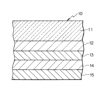
Referring now to Figure 1, a magneto-optical disk
10 includes a transparent protection substrate 11. A first
nitride film 12 as a first transparent dielectric film, a
magnetic film with perpendicular anisotropy 13, a second
nitride film 14 as a second transparent dielectric film,
and a reflection film 15 are successively layered on the
substrate 11 in this order, to form a multiple layered
structure of the magneto-optical disk 10.
The substrate 11 is made of glass with a
thickness of 1.2 mm, for example. Polycarbonate (PC),
polymethyl methacrylate (PMMA) or amorphous polyolefin
(APO) may be utilized as a material for the substrate 11
instead of glass.
The first nitride film 12 and the second nitride
film 14 are made from AeN (aluminum nitride) with a film
thickness of 50 nm which has a refractive index of 2.05,
for example.
The magnetic film 13 is made from TbFeCo (terbium
iron cobalt) with a film thickness of 20 nm, which has a
refractive index of [(3.20-3.55i)+(0.05-0.03i)] with
respect to a reproducing light wavelength of 780 nm, and a
refractive index of [(2.5-2.4i)+(0.008-0.025i)] with
respect to a reproducing light wavelength (~) of 390 nm,
wherein i represents the imaginary part, and the sign of
the refractive index is positive when the magnetization is
directed upward, and negative when it is directed downward.
Rare earth transition metal alloys such as GdTbFe
(gadolinium terbium iron) and DyFeCo (dysprosium iron
- 2036890
cobalt), MnBi (manganese bismuth), MnBiCu (manganese
bismuth copper), Bi substituted garnet, oxide magnetic
bodies of Co ferrite, PtMnSb (platinum manganese antimony),
Pt/Co or Pd/Co may be utilized as a material for the
magnetic film 13 instead of TbFeCo.
The reflection film 15 is composed of an Ae layer
with a thickness of 50 nm, which has a refractive index of
(2-7i) with respect to a reproducing light wavelength of
780 nm, and a refractive index of (0.78-2.2i) with respect
to a reproducing light wavelength of 390 nm.
Gold, silver, copper, nickel or platinum may be
utilized as a material for the reflection film 15 instead
of Ae.
Silicon nitride (SiN), zinc sulfide (ZnS),
silicon aluminum oxide nitride (SiAeON), aluminum nitride
germanium (AQNGe) or silicon oxide (sio) may be utilized as
a material for the first and second nitride films 12, 14
instead of AeN.
The magneto-optical disk 10 thus constructed,
enhances the circular dichroism effect and the magneto-
optical Kerr effect depending on the wavelength of the
incident reproducing light, because of its multiple layered
structure.
Hereinbelow, the calculation results of the
magneto-optical Kerr rotation angle ~ and the ellipticity
~ by means of simulation will be explained with reference
to Figures 2 and 3. In the first example, the nitride film
14 is made of AeN with the refractive index of 2.05 and the
film thickness thereof is varied from o to 200 nm.
Figure 2 presents the calculation results with
respect to a reproducing light wavelength of 780 nm, while
Figure 3 presents the same with respect to the reproducing
light wavelength of 390 nm.
In Figures 2 and 3, the ellipticity ~ is a value
determined by the complex reflecting index depending on the
direction of the magnetization recorded on the magnetic
film 13. This is because the thickness of the nitride film
2036890
",
14 affects the magnitude of the Kerr effect much more than
thicknesses of other films. The calculation is made
according to the method of A.E. Bell (IEEE,QE-14(7),1978).
As shown in Figure 2, by setting the thickness of
the nitride film 14 at about 80 nm as indicated by an arrow
Al, the ellipticity ~ can be made to be about 2.1 with
respect to a wavelength of 780 nm.
On the other hand, as shown in Figure 3, by
setting the thickness of the nitride film 14 at about 80 nm
as indicated by an arrow A2, the Kerr rotation angle ~k can
be made to be about 0.44 with respect to a wavelength of
390 nm.
Accordingly, in this first example, on one hand,
the Kerr rotation angle ~ can be made to be about 2.6 times
as large as that of a single layer TbFeCo structure (in
which the ellipticity ~ is about 0.14 with respect to a
wavelength of 780 nm, while the Kerr rotation angle ~k iS
about 0.17 with respect to a wavelength of 390 nm). On
the other hand, the ellipticity ~ can be made to be about
4.8 times as large as that of the above-mentioned single
layer TbFeCo structure. That is to say, the circular
dichroism effect can be enhanced as the ellipticity ~ is
made large, while the Kerr effect can be enhanced as the
Kerr rotation angle ~ is made large, due to the multiple
layered structure of this first example.
As described above, by forming the magneto-
optical disk 10 having the multiple layered structure with
the film thicknesses of the first example, the bit pattern
recorded on the magnetic film 13 using a light beam with a
wavelength of 390 nm, can be reproduced by the detection of
the reflected light intensity, i.e. by a ROM or WORM
optical disk reproducing apparatus, such as a CD player for
example, which uses a reproducing light beam with the
wavelength of 780 nm.
As a second example of the first embodiment, the
thicknesses of the first nitride film 12, the magnetic film
13, the second nitride film 14 and the reflection film 15
-- 10 --
2036890
are set to 80 nm, 20 nm, 20 nm and 50 nm, respectively, in
the multiple layered structure of the first embodiment.
In this second example, the ellipticity ~ can be
made to be 0.61 with respect to a wavelength of 390 nm,
while the Kerr rotation angle ~ can be made to be 1.3 with
respect to a wavelength of 780 nm.
In this second example, on one hand, the Kerr
rotation angle ~ can be made to be about 3.0 times as large
as that of a single layer TbFeCo structure (in which the
ellipticity ~ is about 0.34 with respect to a wavelength
of 390 nm, while the Kerr rotation angle ~ is about 0.43
with respect to a wavelength of 780 nm). On the other
hand, the ellipticity in this second example can be made to
be about 1.8 times as large as that of a single layer
TbFeCo structure. That is to say, the circular dichroism
effect can be enhanced as the ellipticity ~ is made large,
while the Kerr effect can be enhanced as the Kerr rotation
angle ~ is made large, due to the multiple layered
structure of this second example.
As described above, by forming the magneto-
optical disk 10 in the multiple layered structure with the
film thicknesses of the second example, the bit pattern
recorded on the magnetic film 13 by a magneto-optical disk
recording/reproducing apparatus using a light beam with a
wavelength of 780 nm, can be reproduced by the detection of
the reflected light intensity, i.e. by a ROM or WORM
optical disk reproducing apparatus, which uses a
reproducing light beam with a wavelength of 390 nm.
The above-mentioned reproducing light with a
wavelength of 780 nm is, for example, generated by a
semiconductor laser source with 40 mW output power, while
the reproducing light with a wavelength of 390 nm is, for
example, generated by SHG (Second Harmonic Generator) with
3 mW output power.
The wavelength of the reproducing light is not
limited to 780 nm or 390 nm (one half of the first
-- 11 --
20368 90
..
wavelength). Many different types of wavelengths ~ can be
utilized by different types of the light sources.
Figure 4 shows the construction of the optical
system used in the reproducing operation of the magneto-
optical disk 10. In this reproducing optical system, thecircular dichroism effect is used for detection. That is
to say, this optical system is constructed as a ROM optical
disk reproducing apparatus, such as a CD player or a VD
(video disk) player, in which the circularly or
elliptically polarized light beam is inputted and the
recorded information is detected as the reflected light
intensity.
In Figure 4, the optical system includes a
semiconductor laser source 21. The laser source 21 emits
a linearly polarized light beam as a reproducing light
beam.
The optical system also includes a beam splitter
22 and a ~/4 plate 23. The reproducing light beam is
transmitted through the beam splitter 22 and the plate 23.
At the plate 23, the light beam is changed to a circularly
polarized or elliptical light beam. The light beam is then
irradiated on the magneto-optical disk 10, where it is
reflected toward a light detector 25 through the plate 23,
the beam splitter 22 and lenses 24.
When the reflected light beam is transmitted
through the plate 23, it becomes a linearly polarized light
beam which polarization plane is rotated by 90. Thus, the
reflected light beam is reflected by the beam splitter 22
and directed toward the detector 25.
At this time, the reflected light intensity
corresponds to the information recorded on the magneto-
optical disk 10, i.e. the direction of the magnetization of
the magnetic film 13, because the circular dichroism effect
is enhanced by the magneto-optical disk 10. The reflected
light intensity is detected and changed to an electrical
signal as reproduced data at the light detector 25.
2036890
._
As described above, the optical system of the
first embodiment can be made in a simple form, compared
with an optical system using the Kerr effect, except the
arrangement of the plate 23 for obtaining the circular
polarization. Thus, the optical system and the disk
driving apparatus for reproducing the magneto-optical disk
by use of the circular dichroism effect for the magneto-
optical signal detection of the first embodiment can be
constructed in a compact form with a reduced weight,
compared with the optical system using the Kerr effect.
Referring now to Figure 5, a second embodiment of
a magneto-optical disk 30 includes transparent protection
substrates 31 and 36. An AeN film 32 is formed on the
lower surface of the substrate 31. An AeN film 35 is
formed on the upper surface of the substrate 36. Recording
films 33 and AQN films 34 are formed between the AeN films
32, 35 alternatively and successively, to form a multiple
layered structure of the magneto-optical disk 30.
Each of the AeN films 32, 34 and 35 is composed
of a transparent dielectric film. SiN, ZnS, SiAeoN~ AeNGe
or sio may be utilized as a material of the films 32, 34,
35 instead of AeN.
The AeN film 32 has a refractive index of 2.05,
for example, and a thickness of 100 nm. Each of the films
34 has a refractive index of 2.05, for example, and a
thickness of 0.5 nm. The film 35 has a refractive index of
2.05, for example, and a thickness of 75 nm.
Each of the films 33 is made from TbFeCo with a
thickness of 0.5 nm, which has a refractive index of
t(3.20-3.55i)+(0.05-0.03i)] with respect to a reproducing
light wavelength (~) of 780 nm, wherein i represents the
imaginary part, and the sign of the refractive index is
positive when the magnetization is directed upward, and
negative when it is directed downward.
Rare earth transition metal alloys, such as
GdTbFe and DyFeCo, MnBi, MnBiCu, Bi substituted garnet,
oxide magnetic bodies of Co ferrite, PtMnSb, Pt/Co or
20368~U
Pd/Co, may be utilized as a material of the recording films
33 instead of TbFeCo.
Each of the substrates 31 and 36 is made of
glass. PC, PMMA or APO may be utilized as a material for
the substrates 31, 36 instead of glass.
The magneto-optical disk 30 thus constructed,
enhances the circular dichroism effect and the magnetic
Kerr effect when a reproducing light beam is incident
thereto due to its multiple layered structure.
Figure 6 shows the construction of the optical
system used in the reproducing operation of the magneto-
optical disk 30. This optical system is constructed as a
ROM or WORM optical disk reproducing apparatus, in which
the circularly or elliptically polarized light beam is
incident on the magneto-optical disk 30 and the recorded
information is detected as the intensity variations of the
reflected light.
In Figure 6, the optical system includes a beam
splitter 41, a ~/4 plate 42 and an objective lens 43. The
linearly polarized reproducing light beam with a wavelength
of 780 nm, from a light source (not shown) such as a
semiconductor laser source, is introduced to the beam
splitter 41.
The light beam is transmitted through the beam
splitter 41 and the plate 42. At the plate 42, the light
beam is changed to a circularly or elliptically polarized
light beam. Then, the light beam is irradiated through the
lens 43 on the magneto-optical disk 30 from the side of the
substrate 36. The light is then reflected from the
recording films 33 and introduced to the beam splitter 41
through the lens 43 and the plate 42.
When the reflected light beam is transmitted
through the plate 42, it becomes a linearly polarized light
beam which polarization plane is rotated by 90. Thus, the
reflected light beam is reflected by the beam splitter 41
and directed toward the light detector 46 through a
condensor lens 44 and a cylindrical lens 45.
- 14 -
- ~o36890
At this time, the reflected light intensity
corresponds to the information recorded on the magneto-
optical disk 30, i.e. the direction of the magnetization of
the recording films 33, because the circular dichroism
effect is enhanced by the magneto-optical disk 30. The
reflected light intensity is detected and changed to an
electrical signal as reproduced data at the light detector
46.
As described above, the optical system of the
second embodiment can be made in a simple form, compared
with an optical system using the Kerr effect, except the
arrangement of the plate 42 for obtaining the circular
polarization. Thus, the optical system using the circular
dichroism effect for the magneto-optical signal detection
as the second embodiment, can be constructed in a compact
form with reduced weight.
Hereinbelow, the calculation results of the
ellipticity ~ by means of simulation will be explained as
for the magneto-optical disk 30.
The ellipticity ~ is a value determined by the
complex refraction index depending on the directional
difference of the magnetization recorded on the recording
films 33. The calculation is made according to the method
of A.E. Bell.
With respect to the light beam with a wavelength
of 780 nm as shown in Figure 6, the ellipticity ~ can be
made to be about 0.85. This value of ellipticity ~ is
about 6.1 times as large as that of a single layer TbFeCo
structure (in which the ellipticity ~ is about 0.14 with
respect to a wavelength of 780 nm). That is to say, the
circular dichroism effect can be enhanced as the
ellipticity ~ is made large due to the multiple layered
structure of the second embodiment.
As described above, by forming the magneto-
optical disk 30 in the multiple layered structure with theaforementioned film thicknesses, the bit pattern, which is
magneto-optically recorded on the magneto-optical disk 30,
- 15 -
2036890
can be reproduced by a ROM optical disk reproducing
apparatus such as a CD player, using a reproducing light
beam with a wavelength of 780 nm which enhances the
circular dichroism effect.
Figure 7 shows another construction of the
optical system used in the reproducing operation of the
magneto-optical disk 30. This optical system is
constructed as a magneto-optical disk reproducing
apparatus, in which the linearly polarized light beam is
incident on the magneto-optical disk 30 and the recorded
information is detected as the rotation of the polarization
plane of the reflected light.
In Figure 7, the optical system includes a half
mirror 51, an objective lens 52, a condensor lens 53 and a
beam splitter 54. The reproducing light beam of a linearly
polarized type with a wavelength of 830 nm, from a light
source (not shown) such as a semiconductor laser source, is
irradiated on the magneto-optical disk 30 from the side of
the substrate 31. The light is then reflected from the
recording films 33 and introduced to the mirror 51 through
the objective lens 52. Then the reflected light beam is
reflected at the half mirror 51 and directed toward the
beam splitter 54 through the condensor lens 53.
At the beam splitter 54, the reflected light beam
is divided into a P polarization component and an S
polarization component.
At this time, the rotation of the polarization
plane of the reflected light corresponds to the information
recorded on the magneto-optical disk 30, i.e. the direction
of the magnetization of the recording films 33, because the
magneto-optical Kerr effect is enhanced by the magneto-
optical disk 30. The P polarization component and the S
polarization component are detected by each of light
detectors 55 and 56. The light intensity of the P
polarization component is changed to an electrical signal
at the light detector 55, while the light intensity of the
S polarization component is changed to an electrical signal
- 16 -
203689~
at the light detector 56. Then, the difference between the
output signals from the light detectors 55 and 56 is
amplified as reproduced data.
As described above, the magneto-optical disk 30
can be reproduced by a magneto-optical disk reproducing
apparatus using the magnetic Kerr effect.
Hereinbelow, the calculation results of the
magnetic Kerr rotation angle ~ by means of simulation will
be explained, as for the magneto-optical disk 30. The
calculation is made according to the method of A.E. Bell.
With respect to the light beam with a wavelength
(A) of 830 nm as shown in Figure 7, the Kerr rotation angle
~ can be made to be about 1.13. This value of the Kerr
rotation angle ~ is about 2.6 times as large as that of a
single layer TbFeCo structure (in which the Kerr rotation
angle ~ is about 0.43 with respect to a wavelength of 830
nm). That is to say, the Kerr effect can be enhanced as
the Kerr rotation angle ~ is made large due to the multiple
layered structure of the second embodiment.
As described above, by forming the magneto-
optical disk 30 in the multiple layered structure with the
aforementioned film thicknesses, the bit pattern, which is
recorded on the recording films 33 by a magneto-optical
disk recording/reproducing apparatus, can be reproduced by
the magneto-optical disk reproducing apparatus using a
reproducing light beam with a wavelength of 830 nm.
The wavelength of the reproducing light is not
limited to 780 nm or 830 nm. Many different types of
wavelengths ~ can be utilized by different types of the
light sources for recording and reproducing. Especially,
for recording and for reproducing, light beams of the same
wavelength may be used, or light beams of a different
wavelength may be used.
In the above-described construction of the second
embodiment, the magneto-optical disk 30 has two substrates
31 and 36. However, the magneto-optical disk can be
constructed to have only one substrate with a transparent
- 2036890
protection coating film in place of the other substrate,
which may be made of an ultraviolet hardening polymer, for
example.
The number of recording films 33 can be increased
or decreased, and the thickness of the film 33 and other
films can be also changed, where the thickness of the
recording films 33 may be either constant or variable.
In the above-described embodiments, reflected
light is detected for signal detection, but transmitted
light through the magneto-optical disk may be detected
instead of the reflected light.
- 18 -