Note: Descriptions are shown in the official language in which they were submitted.
-1- 2037229
E~ISE BLOCR ADAPTERS E'OR TERMINAL BLOCRS
Background of the Invention
The invention relates generally to the
combination of a fuse block and a terminal block for
electrical apparatus, and more particularly to apparatus
for joining a conventional fuse block to a conventional
terminal block to form such a combination.
The combination of a terminal block, a fuse
block, and a transformer is known. One advantage of this
combination is that the terminal and fuse blocks can be
supported on the transformer above its mounting plate.
Thus, separate places need not be provided on a circuit
board for a transformer, a terminal~block, and a fuse
block.
Prior combinations of fuse blocks and terminal
blocks have been specially fabricated, low-volume parts,
since the number and types of fuses and terminals used
with a transformer vary. Thus, such combinations have the
disadvantage of being expensive. Individual transformers,
fuse blocks, terminal blocks, and transformer/terminal
`~L
.~
2037229
block comblnatlons, on the other hand, have been standardlzed
and are mass manufactured at low cost. Thus, lt would be
deslrable to lnstall one or more standard fuse blocks on a
standard termlnal block ln an economlcal manner.
Another dlsadvantage of speclally fabricated fuse
block/termlnal block assemblies is their lack of flexibility.
A clrcult manufacturer who uses termlnal blocks and fuse
blocks in several types of apparatus must elther keep separate
lnventorles of each speclally fabricated fuse block/termlnal
block assembly or lose the advantages of uslng such
assemblles. Nelther cholce ls deslrable.
Customers may also want to modlfy or repalr a
preexlstlng clrcuit contalning a transformer and termlnal
block by addlng a fuse block or replaclng an exlsting fuse
block. Many exlsting devlces cannot be modlfled or repalred
ln this manner.
One partlcular transformer and termlnal block
assembly whlch could deslrably be supplemented by a fuse block
ls shown ln U.S. Patent No. 4,804,340, lssued to Hamer, et al.
on February 14, 1989. Thls patent ls hereby lncorporated by
reference ln lts entlrety hereln to show a transformer and
terminal block assembly for use wlth the present lnventlon.
Summary of the Inventlon
The present lnventlon ls an adapter for mechanlcally
~olnlng a termlnal block and a fuse block to support the fuse
block; the termlnal block havlng at least one external
surface, at least one bay recessed ln the external surface,
and a bay termlnal wlthln the bay; the fuse block comprlslng
opposed flrst and second sldes, fuse engaglng means fastened
- 2 -
66597-88
20372~9
to the flrst slde, and fuse terminals; said adapter comprislng
a plate having opposed first and second sides; flrst fastenlng
means for attachlng the flrst slde of sald plate to the fuse
block second slde; and second fastenlng means for attachlng
the second slde of sald plate to the termlnal block adjacent
to the external surface thereof.
The adapter can preferably be lnterposed between a
standard fuse block and a standard termlnal block to ~oln them
together.
The lnventlon can provlde an lnexpensive adapter and
allow a new or dlfferent fuse block to be lnstalled on an
exlsting terminal block. The fuse block can be lnstalled on a
terminal block wlthout reworklng the termlnal block or the
fuse block. The adapter preferably shields the termlnals of
the termlnal block wlthout lmpairlng access to and use of the
terminals.
One feature of the preferred embodlment ls that the
usual terminal screws of a standard termlnal block can be used
to mechanlcally attach the adapter plate to the
66597-88
2037229
terminal block. No electrical connection of the fuse
block to the adapter plate or terminal block is required.
The separation of mechanical and electrical connections
provides the maximum possible flexibility of use.
Another feature of the preferred embodiment is
that the fuse blocks can be mounted singly or ganged,
using the same adapter.
Brief DescriPtion of Drawin~s
Figure 1 is an exploded perspective view of a
first embodiment of the present invention.
Figure 2 is a section of the assembled parts of
Figure 1, taken along line 2--2 of figure 1.
Figure 3 is an exploded perspective view of a
second embodiment of the present invention.
Figure 4 is a section of the assembled parts of
Figure 3, taken along line 4--4 of Figure 3.
Detailed Description of the Invention
While the invention will be described in
connection with certain preferred embodiments, it will be
understood that the inventors do not intend to limit the
invention to those embodiments. On the contrary, the
inventors intend to protect all alternatives,
modifications, and equivalents as may be included within
the spirit and scope of the invention as defined by the
appended claims.
2037~29
--5--
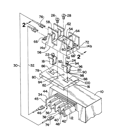
Referring first to Figures 1 and 2, the
transformer 10 and terminal block 12 are made and joined
as described in U.S. Patent No. 4,804,340, which hàs been
incorporated herein by reference. In Figure 1, only a
single terminal block is shown. However, in the structure
shown in the patent incorporated by reference, a terminal
block 12 is located on each side of the transformer, one
facilitating connections to the input leads and the other
facilitating connections to the output leads of the
transformer.
The fuse block 14 is a double fuse block, one
example of which is a gang of two LittelfuseX Class CC
fuse blocks, part L60030C-lPQ, as described in U.S. Patent
No. 4,767,339, issued to Comerci on August 30, 1988. Each
fuse holder of the gang is separable from the others. A
single fuse block can be used, or two or more single fuse
blocks can be ganged together. Here, the single fuse
blocks are labeled 14a and 14b.
The adapter according to the present invention
comprises an adapter plate 16, adapter clips 18 and 20,
and terminal screws 22 and 24 which are the screws
normally used with the terminal block 12 to fasten leads
to the terminals. Screws 26 and 28 secure the fuse blocks
14a and 14b to the adapter plate 16. The jumper wires 30
and 32 are used to make electrical connections between the
screw terminals of the terminal block 12 and the fuse
block 14.
The terminal block 12 comprises flanges 34, 36,
38, 40 and 42. Each flange such as 34 has an upper edge
44 and a side edge 45, the coplanar upper edges such as 44
defining an external surface of the terminal block 12.
2~1372~9
--6--
The space between two adjacent flanges such as 40 and 42
defines a terminal bay 46 recessed in the external
surface. Typically, an electrical terminal such as the
lug 48 is located within each bay, enough bays being
provided in one or more terminal blocks to allow separate
connections to be made to all the input and output leads
of the transformer or other apparatus. Excepting the
terminal lugs such as 48, the entire terminal block 12 is
typically made of an electrically insulating material, and
the terminal lugs such as 48 are recessed sufficiently to
prevent casual contact by a person or any apparatus in the
vicinity. In this embodiment, each terminal lug such as
48 has an aperture 50 which receives a terminal screw such
as 24 having a head such as 52. In the conventional use
of a terminal block 12, the head 52 bears against the
surface of the lug 48 when no terminal is attached. When
a wire terminal is present, it is clamped between the lug
48 and the head 52 to provide a secure mechanical and
electrical connection.
The specific features of the fuse block 14
relevant herein are opposed first (or top) and second (or
bottom) sides 54 and 56 and fuse engaging means. Here,
the fuse-engaging means are the pairs of fuse clips 58, 60
and 62, 64 which receive conventional cartridge fuses and
are respectively connected to the fuse terminals 66, 68,
70, and 72. Typically, one terminal of each fuse is
connected to a terminal of the block 12, and the other
terminal of the same fuse is left open to allow a
connection to an external circuit. Thus, the fuse
terminals 66-72 serve as the terminals of the assembly.
To make the necessary electrical connections between the
20~7229
--7--
terminal block 12 and the fuse block 14, the jumper wire
30 has a wire terminal 74 received by and clamped between
the head 52 and lug 48 and a wire terminal 76 for
connection to the fuse terminal 66. Similar ends and
connections are provided for the jumper wire 32.
Turning in particular to the adapter shown in
Figures 1 and 2, the adapter plate 16 has opposed first
(or top) and second (or bottom) sides 78 and 80, and is
made of electrically insulative material in the preferred
embodiment. One suitable material is conventional
phenolic-impregnated fiber board.
The adapter includes first fastening means for
attaching the first side 78 of the adapter plate 16 to the
second side 56 of the fuse block 14. In this embodiment,
the first fastening means comprises apertures 82 and 84 of
the adapter plate 16 which receive the self-tapping screws
26 and 28. The shafts of the screws 26 and 28 are passed
through the mounting holes such as 85 of the fuse blocks
14a and 14b. Since disassembling the ganged blocks 14a
and 14b requires one of the fuse blocks to be slid
vertically with respect to the other fuse block, and since
both fuse blocks are mounted on a common surface (the
first side 78), a single mounting screw for each fuse
block is sufficient to prevent the fuse blocks from
pivoting.
The adapter plate 16 is secured to the terminal
block 12 using second fastening means. The second
fastening means comprises the apertures 86 and 88, adapter
clips 18 and 20, and terminal screws 22 and 24. Each clip
such as 20 is generally U-shaped, comprising a bight
portion 90 and upstanding legs 92 and 94, each leg such as
-8- 203~229
94 terminating in a pair of ears such as 96. Each adapter
clip such as 20 also has an aperture such as 98 to pass
the threaded shaft of the terminal screw such as 24.
Each aperture such as 88 allows the bight
portion 90 to drop through the adapter plate 16. Each
aperture such as 88 includes two pairs of partial depth
slots such as 100, each about as deep as the ears 96. The
slots 100 receive the ears 96, so the tops of the legs 92
and 94 are substantially flush with the first side 78 of
the adapter plate 16 and can drop no further. When the
fuse block 14 is attached to the first side 78 by the fuse
block screws 26 and 28, the adapter clips 18 and 20 are
captured by the second side 56 of the fuse block 14. The
separation between the ears such as 96 and the bight
portion 90 of each adapter clip such as 18 is such that
the bottom of the bight portion rests slightly above the
terminal lug such as 48 when the assembly of Figure 1 is
put together.
The apparatus is assembled as follows. First,
all the wire terminals such as 74 are led to the
appropriate terminal lugs such as 48 of the terminal block
12. The terminal screws 22 and 24 which are to be used
for attaching the adapter are removed from the terminal
lugs such as 48 at this point. The terminal screws which
are not used for attaching the adapter are advanced to
clamp the corresponding wire terminals in place.
The adapter clips 18 and 20 are inserted in the
apertures 86 and 88, and the adapter plate 16 is placed so
its second side 80 abuts the external surface defined by
the upper edges such as 44 of the terminal block 12. The
bight portions such as 90 of the adapter clips such as 20
2037229
bear against the wire terminals such as 74. When a
terminal screw such as 24 is installed and tightened, its
head 52 bears against the margin of the bight portion 90
outside the aperture 98. The wire terminals such as 74
received by the terminal lugs such as 48 are clamped
between the surface of the terminal lug such as 48 and the
bight portion such as 90.
Before or after the terminal block 12, fuse
block 14, adapter plate 16, and associated parts are
assembled as just described, the wire terminals such as 76
of the jumper wires such as 30 are connected in the usual
manner to the fuse terminals such as 70. The electrical
connections between the terminals (such as the lug 48) of
the terminal block 12 and the corresponding terminals
(such as 70) of the fuse block 14 are thus completed. The
mounting of the terminal block on a transformer can be
carried out conventionally or according to U.S. Patent No.
4,804,340, issued to Hamer et al., incorporated by
reference previously. The installation of the transformer
on the chassis or circuit board of an electrical or
electronic apparatus, the connection of the remaining
terminals of the fuse block to such apparatus, and the
circuit comprising a transformer, fuses, and other
apparatus may be conventional.
The clips 18 and 20 could be made of an
insulating material within the scope of the invention.
However, for ease of fabrication and durability, and to
provide the best possible connection between the wire
terminals such as 74 and terminal lugs such as 48, the
clips are desirably made of electrically conductive metal.
2037229
--10--
The fuse block screws 26 and 28 are used to
attach the fuse block 14 to the apertures 82 and 84 of the
adapter plate 16. Electrical leads such as the jumper
wires 30 and 32 already connected to the desired terminals
of the terminal block 12 may then be attached to the
desired terminals of the fuse block 14.
While securing the jumper wires 30 and 32
represents an extra step in assembling the present
combination, the use of jumper wires provides extra
flexibility in the provision of electrical connections
between a standard fuse block and a standard terminal
block. There is no need to electrically connect any
particular terminal of the block 12 to a particular fuse
terminal. The adapter plate 16 can be narrower to
accommodate a single fuse block such as 14a or wider to
accommodate three or more fuse blocks within the scope of
the present invention.
Referring now to Figures 3 and 4, a second
embodiment of the invention will be described. In this
embodiment, the transformer 110, terminal block 112, fuse
blocks 114a and 114b, and jumper wires 116 and 118
correspond to their counterparts in the first embodiment,
except that in this embodiment the terminal block 112 has
lugs such as 120 on its opposed side faces 122 and 123
which are engaged by the fingers 124, 126 extending
perpendicularly from the second surface 128 of the adapter
plate 130.
The fingers such as 126 and the lugs such as 120
have complementary bevelled surfaces 132 and 134, and the
fingers 124 and 126 are made of resilient material. Thus,
the fingers 124 and 126 are displaced outward as the
2037~29
adapter plate 130 is pushed down and the surfaces 132 and
134 engage each other. When the lugs such as 120 are
registered with the slots such as 136 of the fingers such
as 126, the lugs such as 120 are received in the slots
such as 136 and the fingers 124 and 126 snap against the
side faces 122 and 123. In this embodiment, it is easier
to snap the adapter plate 130 onto the terminal block 112
than to remove it, since the lower faces of the lugs 120
are not bevelled. The fingers 124 and 126 can be pried
apart, however, to disengage the slots 136 from the lugs
120.
By a slight modification of structure the lugs
120 (which represent a modification of a standard terminal
block 112) would not be necessary. The fingers 124 and
126 could be provided with inward barbs at their lower
ends which would be received under the lower edges such as
138 of the faces such as 123.
To attach the fuse blocks 114a and 114b to the
adapter plate 130, the fuse block screws 26, 28 and
apertures 82 and 84 of the first embodiment are replaced
by split stakes such as 140, each having a neck 142 sized
to pass through a corresponding aperture 143 of a fuse
block such as 114a (which will accept either a stake or a
screw), and upper ends 144 which are barbed and resilient.
The upper ends 144 are urged together when their
respective beveled upper surfaces bear against the margin
of the aperture 143 of the fuse block 114b and spring
apart when they emerge from the aperture 143, locking the
barbs over the margins of the aperture 143. A particular
advantage of the structure of Figures 3 and 4 is that the
adapter plate 130 can be a single molded plastic part.
2037229
-12-
Thus, apparatus has been shown for physically
mounting one or more fuse blocks on a terminal block, each
of which can be a standard part. The adapter can be
inexpensive and can allow a first or additional fuse block
to be installed on an existing terminal block in a
circuit. The adapter plates 16 and 130 also shield the
terminals of the terminal blocks, 12 and 112, from the
environment without impairing access to or use of the
terminals. Thus, one or more of the objects of the
present invention are realized.