Language selection

Search

Patent 2037249 Summary

Third-party information liability

Some of the information on this Web page has been provided by external sources. The Government of Canada is not responsible for the accuracy, reliability or currency of the information supplied by external sources. Users wishing to rely upon this information should consult directly with the source of the information. Content provided by external sources is not subject to official languages, privacy and accessibility requirements.

Claims and Abstract availability

Any discrepancies in the text and image of the Claims and Abstract are due to differing posting times. Text of the Claims and Abstract are posted:

  • At the time the application is open to public inspection;
  • At the time of issue of the patent (grant).
(12) Patent: (11) CA 2037249
(54) English Title: IMPLEMENT SUSPENSION MECHANISM
(54) French Title: SUSPENSION POUR INSTRUMENT ARATOIRE
Status: Deemed expired
Bibliographic Data
(52) Canadian Patent Classification (CPC):
  • 56/49
(51) International Patent Classification (IPC):
  • A01D 67/00 (2006.01)
  • A01B 59/044 (2006.01)
  • A01D 34/64 (2006.01)
(72) Inventors :
  • KUHN, JOHN BOYD (United States of America)
  • HUNT, KENNETH EDWARD (United States of America)
  • THORMAN, CHRISTOPHER SCOTT (United States of America)
(73) Owners :
  • DEERE & COMPANY (United States of America)
(71) Applicants :
(74) Agent: BORDEN LADNER GERVAIS LLP
(74) Associate agent:
(45) Issued: 1994-04-26
(22) Filed Date: 1991-02-27
(41) Open to Public Inspection: 1991-09-06
Examination requested: 1991-02-27
Availability of licence: N/A
(25) Language of filing: English

Patent Cooperation Treaty (PCT): No

(30) Application Priority Data:
Application No. Country/Territory Date
07/488,807 United States of America 1990-03-05

Abstracts

English Abstract


IMPLEMENT SUSPENSION MECHANISM
Abstract of the Disclosure
A mechanism for suspending an implement from a vehicle,
such as a lawn and garden tractor. The mechanism includes
front and rear supports between the vehicle and implement, the
supports being adapted for quick and easy connection. The
rear supports include spring-loaded J-pins connectable with
the tractor lift linkage. The front support includes a U-
shaped member, the base of which is receivable in upwardly
opening jaws carried on the implement. The sides of the U-
shaped member serve as draft links and are adjustably coupled
with a cross member that is receivable in similar jaws carried
by the tractor. A latch handle is connected to a bell crank
which is provided on the cross member for tensioning the draft
links and securing them in their tensioned configuration.


Claims

Note: Claims are shown in the official language in which they were submitted.


The embodiments of the invention in which an exclusive
property or privileged is claimed are defined as follows:

1. A mechanism for mounting an implement from a vehicle
comprising:
first and second support means carried between the
vehicle and implement,
each support means including pin means receivable
through an opening of a bracket, the pin means being biased
towards engagement with the opening;
hanger means supporting the implement from the
vehicle, said hanger means including first and second spaced
apart jaw means carried by the implement and the vehicle
respectively, a U-shaped member having leg portions joined to
a transversely extending first cross member, the cross member
being adapted to be received in one jaw means, a second
elongated cross member connected with the leg portions, spaced
from the first cross member and receivable in the other jaw
means, cam means coupled with one cross member and operable to
shift the leg portions between forward and rearward positions;
and
latch means operatively coupled to the cam means for
securing the leg portions in one of their positions.
2. A mechanism for detachably mounting an implement
from a vehicle having upwardly opening hook means carried
thereon, comprising:
first and second transversely spaced bracket means,
each bracket means including a U-shaped pin means connectable
with the vehicle;
draft linkage means fore and aft spaced of the first
and second bracket means, said linkage means including
upwardly opening hook means carried by the implement;
hanger means having first and second fore and aft
spaced cross members receivable respectively in the hook means
of the vehicle and the implement,
said hanger means further including cam means
attached to one cross member and a handle connected to the cam
means for rocking the cam means between first and second
positions whereby the first and second hook means are moved
between closer and spaced apart positions.


3. Mechanism for releasably suspending one end of an
implement from a vehicle having bracket means carried on the
lower portion thereof, said bracket means including a first
pair of transversely spaced apart and upwardly opening jaw
means;
a second pair of transversely spaced apart and
upwardly opening jaw means carried at the forward portion of
the implement, said second jaw means adapted to be positioned
fore and aft spaced from the first jaw means;
a pair of transversely spaced apart fore and aft
extending draft links, said links having front and rear
portions;
first and second fore and aft spaced and
transversely extending pivot members extending between and
connecting the respective front and rear portions of the
links, said first and second pivot members being respectively
receivable in the first and second jaw means; and
cam means operatively connected to one pivot member,
shiftable between first and second positions and operable to
shift said pivot member between fore and aft spaced positions
as the cam means is shifted between its first and second
positions.
4. The invention defined in claim 3 wherein the base of
a rod-like U shaped member serves as one pivot member and its
sides serve as the draft links.
5. The invention defined in claim 3 wherein the draft
links have means permitting fore and aft adjustment of their
length.
6. The invention defined in claim 3 wherein one pivot
member is carried within a sleeve member and the draft links
are adjustably coupled with the sleeve member.
7. The invention defined in claim 3 wherein there is
further provided a handle for moving the cam means between its
first and second positions and the handle and vehicle are
provided with latch means between them for securing the cam
means in one of its positions.
8. The invention defined in claim 7 wherein the latch
means includes a lug carried by the handle and a recess


carried by the vehicle, with the lug being selectively
receivable in the recess.
9. The invention defined in claim 3 wherein the cam
means includes a bell crank carried by the one pivot member
and a handle is coupled to one leg of the bell crank.
10. The invention defined in claim 3 wherein stop means
is provided between the one pivot member and the jaw means it
is receivable in, the stop means being selectively effective
to prevent movement of the one pivot member out of the jaw
means.
11. The invention defined in claim 3 where there is
further provided transversely spaced apart bracket means
between the implement and vehicle, said bracket means being
fore and aft spaced from the jaw means of the vehicle and the
implement and including spring loaded J-pins carried by the
implement for registering with the vehicle.


Description

Note: Descriptions are shown in the official language in which they were submitted.


2037249

IMPLEMENT SUSPENSION MECHANISM
Field of the Invention
The present invention relates generally to lawn and
garden vehicles and specifically to suspension means for
mounting an implement such as a mower from such vehicles.
Description of the Related Art
Mechanisms for suspending a mower from a vehicle, such as
a lawn and garden tractor, typically are directed at providing
an even cut of grass. Anti-scalp wheels or rollers are
usually also provided on the mower to accommodate bumps and
other uneven terrain during operation.
Many present suspension devices provide a parallelogram
linkage arrangement between the front and back portions of the
implement and vehicle to assure that as it is raised or
lowered, the sides, front and rear of the mower are lowered or
raised equally.
Since mowers and similar implements are not utilized full
time with the lawn and garden tractor, such suspension means
must further facilitate quick, easy removal and reinstallation
of the implement and be comprised of as few parts as
realistic. While providing for quick removal or installation,
it is also desirable for the suspension means to be simple and
yet maintain the parallelogram arrangement between connections
on the implement and vehicle to assure that the even cut of5 grass desired at various heights of adjustment is realized.
Summary of the Invention
Accordingly, there is provided herein a mechanism which
permits quick and easy installation and removal of the
implement from the vehicle while also providing a
parallelogram arrangement to assure even cuts of grass.
The invention provides a pair of conventional J-shaped
spring-loaded pins carried by the mower implement for
connecting the rear portions of the mower to the vehicle
frame. At the front portion of the mower, there is provided a
unique and simple draft linkage to connect the front portion
of the mower to the vehicle frame.
The linkage provided at the front of the mower is
comprised of two generally parallel and transverse linkage
members coupled with two generally fore-and-aft extending


2037249

transversely spaced linkage members. A pair of upwardly
opening jaws are carried on the front portion of the implement
frame and the undercarriage of the vehicle for receiving the
respective transversely extending linkage members. A
tensioning means is provided in the form of a cam and handle
and is connected to one transverse linkage member for
tensioning the fore-and-aft linkage members after they have
been positioned in the respective jaws of the implement and
vehicle frame.
Tensioning of the fore-and-aft linkage members provides
positive connection points between the mower and vehicle and
- maintains the desired parallelogram suspension arrangement
required for even cuts of grass.
The cam handle carries a tab and is biased toward the
lS vehicle frame member to enable the tab to be received in a
recess carried in the frame member to positively lock the
handle in place once the links have been tensioned.
A stop member is further provided on the cam member for
engaging one surface of the jaw opening and thereby preventing
unintended separation of the front transverse linkage member
from the vehicle jaws when the mower is backed up.
With the combination of the spring-loaded J-pins at the
rear of the mower and the front suspension linkage which
permits quick and easy insertion and locking in the mower
vehicle jaws, a simple and reliable suspension means is
provided that maintains the parallelogram linkage required to
facilitate even cuts of grass.
Description of the Drawinas
;~ Fig. 1 is a side view of a lawn and garden tractor
utilizing the present invention to support a rotary mower
therebeneath.
Fig. 2 is an enlarged partial view of the Fig. 1
illustrating in greater detail the present invention.
Fig. 3 is an enlarged view of the J-pin bracket
arxangement taken along lines 3-3 as shown in Fig. 2.
Fig. 4 is an enlarged left front side elevational
perspective of the front linkage suspension means.
Fig. 5 is an enlarged right front side elevational
perspective of the front linkage suspension means.

20t~724~
Fig. 6 is an enlarged partial view of the front
suspension means prior to tensioning the draft lengths with
the handle.
Description of the Preferred Embodiment
Looking now to Fig. 1 there is illustrated a lawn and
garden tractor 10 having a rotary mower 12 suspended
therebeneath. The conventional lawn and garden tractor lo
includes front and rear wheels 14 and 16 sufficiently spaced
apart to carry the mower 12.
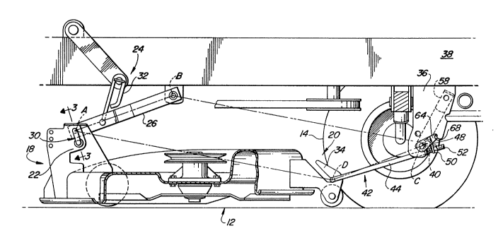
- 10 As illustrated in Fig. 2, provision is made for
suspending the rotary mower 12 from the framework of the
tractor 10 both at the rear 18 and at the front 20 of the
mower 12. The suspension mechanism is designed to provide a
four bar parallelogram linkage for equal lifting of the front
and rear mower housing 20 and 18 as it is adjusted.
The mechanism for releasably suspending the implement 12
from the tractor 10 includes a pair of transversely spaced and
rearwardly positioned brackets 22. A conventional lift
linkage control mechanism 24 includes the lift link 26 for
adjusting the height of the mower 12 beneath the tractor 10.
The brackets 22 are adapted to receive the lift link 26 of the
implement lift linkage mechanism 24 between their respective
walls 28. Conventional spring loaded pins means 30 are
provided to quickly and positively couple the lift links 26
~- 25 with the brackets 22. Fig. 3 illustrates in detail the spring- loaded J-pin 30 and the lift link 26 as seen along lines 3-3
of Fig. 2.
A lost motion link 32 is provided between the lift link
26 of the tractor lift linkage control mechanism 24 for
accommodating upward movement of the mower 12 as uneven
terrain is encountered between the front and rear wheels 14
and 16 of the tractor 10.
Provided at the front portion 20 of the mower 12 are a
pair of transversely spaced apart and upwardly opening jaw or
hook means 34 (see FIGS. 2, 4 and 5). Similarly provided on
the downwardly extending brackets 36 carried by the tractor
frame 38 are upwardly opening jaw means 40. A hanger means 42
for supporting the implement 12 from the vehicle 10 is

2037249
provided to interconnect the upwardly opening jaws 34 and 40
carried respectively by the vehicle 10 and the implement 12.
Looking now to Figs. 4, 5 and 6, there is shown a hanger
means 42 which is comprised of a U-shaped rod~like bar or
`~k 5 member 43 having leg portions 44 joined to a base portion 46.
The base portion 46 is adapted to be received in the upwardly
opening hooks 34 carried by the implement 12. The forward
ends of the leg portions or draft links 44 are received in an
elongated cross-member 48 and secured thereto by nuts 50
received on threaded ends 52 of the U-shaped member 43.
Through adjustment of the nuts 50, the length of the leg
portions 44 can be varied.
The cross-member or sleeve 48 carries a transverse bar 54
having offset end portions 56 which are received in the jaws
40 carried by the tractor brackets 36. Carried at one end of
the transverse bar 54 and rigidly attached to the offset
portion 56 is a handle 58 which carries on its upper end a lug
60 which is receivable in a recess 62 carried on one bracket
36 (See FIGS. 5 and 6).
Carried on the offset portion 56 of the transverse bar 54
at its other end is an ear 64 which carries a stop surface 66
at its end. This ear 64, when positioned as illustrated in
Fig. 4, will extend upwardly and forwardly and have its stop
surface 66 adjacent the downwardly opening abutment or stop
surface 68 carried by the tractor bracket 36.
The operation of the implement suspension mechanism will
now be reviewed. When an operator wants to install the
implement 12 beneath the tractor 10 he will first position the
tractor 10 above the implement 12, so that the two lift links
26 can be inserted into the brackets 22. With the spring
loaded J-pins 30, he need only pull on the J-pin 30 to retract
the top leg 70 from the opening 71, insert the link 26 between
the bracket walls 28 so that the link 26 rests on the lower
leg 72 of the J-pin 30 and then release the J-pin 30. The
spring 74 will urge the top leg 70 of the J-pin 30 back into
the bracket opening 71 and through an aligned opening 73 in
the lift link 26.
After securing the two J-pins 30 in the brackets 22
carried at the rear of the mower 12, he positions the base 46


,:~


;.:
, .- ~

: 2037249
of the U-shaped front hanger means 42 in the hook means 34
carried by the front of the mower 12. Thereafter he positions
the front cross-member 54 in the jaws 40 carried by the
tractor brackets 36, then grasps the handle 58, rotating it
upwardly from the position illustrated in Fig. 6 to that
position illustrated in Fig. 5. As the handle 58 is rotated,
the transverse bar 54 serves as a pivot member and the offset
portions 56 serve as bell cranks or cam means to tension the
` draft links 44 and provide a tight connection between the
tractor brackets 36 and the implement jaws 34. Since the
handle 58 is preferably comprised of a springy or resilient
material, the operator can easily pull it outwardly and away
from the frame bracket 36 as he rotates it upwardly. He then
slips the lug 60 into the recess 62 of the bracket 36 to latch
;~ 15 the handle 58 and the draft links 44 in the desired position.
The nuts 50 provided on the ends of the draft links 44
permit him to quickly make any necessary adjustments and
provide the desired tension in the draft links 44.
Looking again at Fig. 2, there is illustrated a side view
of the suspension mechanism with the four-bar parallelogram
linkage arrangement illustrated by the dotted lines. This
four-bar linkage is provided through the connections A, B, C
and D and assures that as the operator adjusts the height of
the lift linkage 24 at the back 18 of the mower 12, the front
20 of the mower 20 correspondingly will raise an equal amount.
In this manner the operator is assured that the mower 12 is
suspended at an uniform height above the surface for realizing
the desired height of cut.
When the operator wants to remove the implement 12, he
simply reverses the above discussed procedure and stores the
front suspension linkage.

Representative Drawing
A single figure which represents the drawing illustrating the invention.
Administrative Status

For a clearer understanding of the status of the application/patent presented on this page, the site Disclaimer , as well as the definitions for Patent , Administrative Status , Maintenance Fee  and Payment History  should be consulted.

Administrative Status

Title Date
Forecasted Issue Date 1994-04-26
(22) Filed 1991-02-27
Examination Requested 1991-02-27
(41) Open to Public Inspection 1991-09-06
(45) Issued 1994-04-26
Deemed Expired 2007-02-27

Abandonment History

There is no abandonment history.

Payment History

Fee Type Anniversary Year Due Date Amount Paid Paid Date
Application Fee $0.00 1991-02-27
Registration of a document - section 124 $0.00 1991-08-07
Maintenance Fee - Application - New Act 2 1993-03-01 $100.00 1993-02-26
Maintenance Fee - Application - New Act 3 1994-02-28 $100.00 1994-02-25
Maintenance Fee - Patent - New Act 4 1995-02-27 $100.00 1995-02-24
Maintenance Fee - Patent - New Act 5 1996-02-27 $150.00 1996-02-26
Maintenance Fee - Patent - New Act 6 1997-02-27 $150.00 1997-02-26
Maintenance Fee - Patent - New Act 7 1998-02-27 $150.00 1998-02-26
Maintenance Fee - Patent - New Act 8 1999-03-01 $150.00 1999-02-26
Maintenance Fee - Patent - New Act 9 2000-02-28 $150.00 2000-02-25
Maintenance Fee - Patent - New Act 10 2001-02-27 $200.00 2001-02-26
Maintenance Fee - Patent - New Act 11 2002-02-27 $200.00 2002-02-26
Maintenance Fee - Patent - New Act 12 2003-02-27 $200.00 2003-02-26
Maintenance Fee - Patent - New Act 13 2004-02-27 $250.00 2004-02-03
Maintenance Fee - Patent - New Act 14 2005-02-28 $250.00 2005-02-02
Owners on Record

Note: Records showing the ownership history in alphabetical order.

Current Owners on Record
DEERE & COMPANY
Past Owners on Record
HUNT, KENNETH EDWARD
KUHN, JOHN BOYD
THORMAN, CHRISTOPHER SCOTT
Past Owners that do not appear in the "Owners on Record" listing will appear in other documentation within the application.
Documents

To view selected files, please enter reCAPTCHA code :


To view images, click a link in the Document Description column. To download the documents, select one or more checkboxes in the first column and then click the "Download Selected in PDF format (Zip Archive)" or the "Download Selected as Single PDF" button.

List of published and non-published patent-specific documents on the CPD .

If you have any difficulty accessing content, you can call the Client Service Centre at 1-866-997-1936 or send them an e-mail at CIPO Client Service Centre.


Document
Description 
Date
(yyyy-mm-dd) 
Number of pages   Size of Image (KB) 
Cover Page 1994-07-09 1 16
Abstract 1994-07-09 1 23
Claims 1994-07-09 3 121
Drawings 1994-07-09 3 125
Description 1994-07-09 5 250
Representative Drawing 1999-06-30 1 26
Office Letter 1991-08-16 1 22
PCT Correspondence 1994-01-28 1 18
Fees 1997-02-26 1 92
Fees 1996-02-26 1 43
Fees 1995-02-24 1 37
Fees 1994-02-25 1 29
Fees 1993-02-26 1 33