Note: Descriptions are shown in the official language in which they were submitted.
2037~07
Safe~uard for_a sanitary fi~
The present invention relates to a safeguard for
a sanitary fitting for preventing the backflow of water
into a feedline, in accordance with the preamble of claim
1 or 16.
There are sanitary fitti.ngs, in which the quality
of the feed water can be endangered on re-suction of
impure water into the feedline. These include, in par-
ticular, washbasin and sink fittings having a pull-out
hose shower and shower and bath tap units having a hose
shower. It can occur in the case of fittings of this type
that the shower is lying in a basin or in a bath when,
for example, the feedline breaks. If the fitting is open
at that moment, the water in the basin or the bath can be
completely sucked out via the shower due to the negative
pressure which is built up in the feedline due to the
water flowing off. Fittings of this type must have
safeguards, by means of which the re-suction of impure
water into the feedline is prevented.
2~ A safeguard of this type is known from German
Offenlegungsschrift 3,805,462. The fitting has a shutoff
valv~ which is connected in the flow path between the
feedline and the outlet of the fitting. Branching off
from the flow path, seen in the flow direction of the
water, after the shutoff valve is an aeration path, in
which the two valves of the safeguard are connected.
These valves are constructed as sensitive check valves
which, under normal operating conditions, are in the
closed position. Under conditions allowing backflow, the
two valves open automatically and thus aerate the outlet
and the feedline in order to prevent backflow of the
water. It is possible under normal operating conditions,
in particular in the case of rapid closure of the shutoff
valve, for a negative pressure to be built up briefly in
the flow path following the shutoff valve, by which means
valves of the safeguard can be caused to open, which can
lead to the fact that a droplet can emerge through said
valves. In order to prevent this, the &erman
"
- 2 - 2037~07
Offenlequngsschrift mentioned teaches that the two valves
should be arranged successively in such a way that the
negative pressure in the case of a rapid interruption of
the water-drawing process only affects the first valve
situated nearer to the flow path. It is achieved by the
delay between the two valves that, under these operating
conditions, the second valve does not open, with the
result that a water droplet emerging through the first
valve is caught in the region between the two valves. In
the case of a negative pressure lasting longer, such as
occurs under conditions allowing backflow, both valves of
the safeguard open in order to aerate the outlet and to
prevent backflow of water into the feedline. It is
disadvantageous in this known safeguard that the two
valves have to be coordinated with one another extremely
precisely and that they cannot prevent a reliable preven-
tion [sic] of the backflow of water into the feedline
since they do not interrupt the flow path of the fitting
for the water.
Furthermore, a so-called ~combined safeguard~ is
known from DIN 1988, Part 4, which consists of a backflow
preventer and a pipe aerator connected downstream from
the latter seen in the flow direction. Under conditions
allowing backflow, the backflow preventer, constructed as
a check valve, closes off the flow path, whereas the pipe
aerator connects the outlet to the ambient air.
Setting out from this prior art, an object of the
present invention is to provide a safeguard for a
sanitary fitting which reliably prevents backflow of
3~ water into the feedline and emargence of water through
the aeration path.
This object is achieved by the features of the
defining part of claLms 1 and 16.
The two valves of the safeguard according to the
invention are connected in the flow or aeration path of
the fitting in the same manner as the backflow preventer
and pipe aerator in accordance with a combined safeguard
according to DIN 1988, Part 4. Corresponding to claim 1,
the first valve connected in the flow path is constructed
~ _ 3 _ 2037~07
to be automatic and capable of movement between an
operating position and a backflow position. Under normal
operating conditions, the first valve is in the operating
position and, under conditions allowing backflow, is
moved automatically into a backflow position due to the
pressure difference on the two sides of the valve. Since
the valve body of the second valve also executes the
movement of the first valve, the second valve is in-
evitably closed when the first valve is in the operating
position, while the second valve is inevitably opened
when the valve moves into the backflow position. It is
ensured by this means that, under conditions allowing
backflow, the flow path is shut off by the first valve
and the outlet is inevitably aerated at the same time.
Under normal operating conditions, the second valve is
inevitably closed, which prevents emergence of water even
during rapid closure of the shutoff valve.
In an extremely simple safeguard in accordance
with claim 16, the first valve itself is provided in a
stationary manner, in which case, however, for inevitable
actuation of the second valve, its valve body also
executes the movement of the valve body of the first
valve.
Preferred developments of the present invention
are specified in the dependent claims.
The present invention is now described in greater
detail with reference to the exemplary embodiments
illustrated in the drawing, in which, purely
diagrammatically:
Figure 1 shows, partially in section, a sink fitting
having a pull-out hose shower;
Figures 2 to 4 show a safeguard for the fitting in
accordance with Figure 1, under different
operating conditions; and
Figures 5 to 13 show, in section, four further develop-
ments of the safeguard under normal operating
conditions and under conditions allowing
backflow.
The sanitary fitting shown in Figure 1 has a
_ 4 _ 2037~07
fitting housing 10 and a pull-out hose shower 12. The
fitting housing 10 consists essentially of three parts,
a lower and an upper housing part 14 and 16 respectively,
these form a fixed housing part 16a, and a jacket element
20 which is mounted on said housing part so as to be
swivelable about an axis 18 extending essentially in the
vertical direction. The lower housing part 14 is essen-
tially of sleeve-shaped construction, penetrates with an
attachment nozzle 22 an approximately horizontally
extending edge 24 of a sink 26, and is fastened to the
sink 26 by means of a nut 28 screwed onto the attachment
nozzle 22.
The upper housing part 16 is seated on the lower
housing part 14 and is attached to the latter. The
essentially cylindrical fixed housing part 16a, formed by
the lower and upper housing parts 14, 16, is surrounded
by the jacket element 20 which is mounted on said fixed
housing part so as to be swivelable about the axis 18.
The upper housing part 16 has a cylindrical
recess 30 which is open toward the top and has the form
of a blind hole, in which recess a control cartridge 32,
indicated only diagrammatically, is inserted. The control
cartridge 32 is a single-lever mixing valve, such as is
generally ~nown and is described in detail, for example
in the Swiss Patent Specifications 651,119 or 654,088. On
the inlet side, the control cartridge 32 is connected in
each case to a feedline 34 for cold and hot water, only
one of the feedlines 34 being shown in the figure. The
feedlines 34 are guided from below through the attachment
nozzle 22 and the lower housing part 14 and open out into
a bore hole (not illustrated) in the upper housing part
16, which bore hole connects the feedlines 34 to the
control cartridge 32.
Connected downstream from the control cartridge
32 is a safeguard 36, indicated only diagrammatically in
this figure, which is inserted in a further recess 38 in
the upper housing part 16, which recess is open toward
the lower housing part 14 and has the form of a blind
hole. Provided between the recess 30 and the further
2037~07
- 5 -
recess 38 is a passage aperture 40 which connects the
control cartridge 32 in terms o~ flow to the safeguard
36. Guided away from the safeguard 36 in the direction of
the axis 18 toward the bottom is a pipe 42 which is
guided through the attachment nozzle 22 below the sink
26. This end of the pipe 42 is connected to a flexible
hose 44 of the shower hose 12, which hose is guided with
the other end region throu~h the attachment nozzle 22
again, forming a supply loop below the sink 26. The lower
housing part 14 has an aperture 46 extending approx-
imately in the radial direction, passing through which
aperture the end region of the hose 44 is guided into a
nozzle 48 which is molded onto the jacket element 20 and
projects obliquely upward from the latter. The hose 44
opens out into a shower 50, the handle 50' of which is
inserted with the hose-side end region in a guide bush
48' arranged in the nozzle 48 in a manner such that it
can be pulled out again. The outlet of the shower hose 12
is denot~d as 52. The aperture 46 for the hose 44 is of
such a size in the circumferential direction of the lower
housing part 14 that swiveling of the jacket element 20
is possible without any problems.
Provided in the upper housing part 16 is an
aeration channel 54 which extends from the further recess
38 to the nozzle 48. Provided on the upper side of the
nozzle 48 is a hole 56 which, together with the nozzle 48
and the aeration channel 54 connects the safeguard 36 to
the ambient air, forming an aeration path 58. A further
possible development of the aeration path 58 is described
in the Swiss Patent Application 04 481/89-9.
Situated between the feedline 34 and the outlet
52 is the flow path 60 for the water, in which flow path
the control cartridge 32 and, mounted downstream from the
latter seen in the flow direction S of the water, the
safeguard 36 are connected and which has the passage
aperture 40, the pipe 42, the hose 44 and the shower S0.
Figure 2 shows an embodiment of the safeguard 36
which is inserted from below in the further recess 38 of
the upper housing part 16. Advantageously the
2037407
- 6 -
safeguard 36 is attached to the upper housing part 16 in
such a way that it can be dismantled, for example for
servicing, without any problems. Thus it is possible for
the safeguard 36 to be constructed such that it can be
screwed into the upper housing part 16 or attached in a
known manner by means of screws, pins or spring rings.
The water flows from the control cartridge 32 through the
passage aperture 40 in the flow direction S through the
safeguard 36 to the pipe 42, indicated in dashed lines,
which is guided from below into an outlet aperture 62 of
a housing 64 of the safeguard 36. The aeration channel 54
is guided away from the central region of the further
recess 48 obliguely upward through the upper housing part
16 to the nozzle 48 (see Figure 1).
The safeguard 36 has two valves 66, 68, the first
valve 66 being connected in the flow path 60 leading
through the safeguard 36 and the second valve 68 being
connected in the aeration path 58 connecting the flow
path 60 to the ambient air. The second valve 68 is
provided at the entry of the aeration path 58 into the
flow path 60 and is mounted, seen in the flow direction
S, downstream of the first val~e 66.
The housing 64 has an essentially cylindrical
housing recess 70 which is open toward the passage
aperture 40 and has the form of a blind hole, in the base
region of which there is constructed an annular valve
seat 72 for the second valve 68. The valve seat 72
borders and bounds an aeration passage 74 which extends
away from the housing recess 70 downward firstly in the
direction of the axis 64' and then in the radial direc-
tion to a circumferential groove 76 provided on the
housing 64, which circumferential groove is connected in
terms of flow to the aeration channel 54. Extending
around the valve seat 72 there is a groove-shaped inden-
tation 78, from which bore holes 80 begin extending inthe direction of the axis 64', which bore holes connect
the housing recess 70 to the outlet opening 62.
In the housing recess 70, a piston-shaped valve
seat element 82 is guided so as to be displaceable in the
2037~07
-- 7 --
direction of the axis 64'. It has a plurality of flow
apertures 84 arranged in annular fashion around the axis
64' and extending parallel to said axis, which flow
apertures open out at the bottom into an indentation 86
in the valve seat element 82, said indentation being an
upwardly directed bell shape. Provided in this indenta-
tion 86 are both the valve body 88 of the first valve 66
and the valve body 90 of the second valve 68.
The valve body 88 of the first valve 66 has a
bell-shaped form, it consists of rubber-elastic material,
covers the flow apertures 84 and bears with its lower end
region against the inside wall 82' of the valve seat
element 82, which inside wall thus forms the valve seat
of the first valve 88. The valve body 88 is attached to
the valve seat element 82 by means of a shaft 92
penetrating said valve body and the valve body 90 of the
second valve 68 is seated on the free end region of the
shaft 92 projecting in the direction toward the bottom.
Said valve body has a lip 90' interacting with the
annular valve seat 72.
Mounted in the upper end region on the valve seat
element 82 is a step-shaped peripheral widening 94 which,
as the stop 95 acting in the direction S, interacts with
a corresponding stepwise taper 96 in the housing recess
2S 70. This stop 95 defines the operating position of the
valve seat element 82 shown in Figure 2 and thus the
first valve 66.
Inserted in the upper region of the valve seat
element 82 is a perforated disk 98, the holes 98' of
which are in alignment with the flow apertures 84 in the
valve seat element 82. Held at the inner end between the
valve seat element 82 and the perforated disk 98 is an
annular sealing member 100 shaped like a rolled diaphragm
made of rubber-elastic material which surrounds the
widening 94 and the upper end region of the housing 64 in
a U-shape counter to the flow direction S and is held
braced between the housing 64 and the upper housing part
16 by means of a protrusion 100' engaging in a circum-
ferential groove 102 in the housing 64.
2037~07
- a
The perforated disk 98 is attached to the valve
seat element ~2 by means of the ~haft 92. The shaft 92
penetrates the valve seat element 82 and engage~ with its
upper end region 92' of rib-type construction in a blind
hole 104 in the perforated disk 98. The ribs of the upper
end region 92~ of the shaft 92 are of lamella-type
construction, with the result that they prevent the shaft
92 from being released from the blind hole 104. The two
valve bodies 88, 90 are held by means of circumferential
holding ribs 92~' of the shaft 92, the valve body 88 of
the first valve 66 being arranged between the valve seat
element 82 and one holding rib 92" and the valve body 90
of the second valve 68 being arranged between said
holding rib and the other holding rib 92ll.
The valve seat element 82 is constructed coni-
cally widening, seen in the flow direction S, between the
widening 94 and the lower end region, with the result
that the valve seat element 82 is guided on the housing
64 in a sliding manner only at its lower end region. This
reduces the friction between the housing 64 and the valve
seat element 82. Additionally, this prevents scaling
which could impede or preYent displacement of the valve
seat element 82 counter to the flow direction S from the
operating position shown in the figure into a backflow
position shown in Figure 4.
Provided below the circumferential groove 76 is
an O-ring 106 which bears against the upper housing part
16 and is arranged in a corresponding groove in the
housing 64 of the safeguard 36. Thus the circumferential
3Q groove 76 is sealed off at the top by the protrusion 100'
of the sealing member 100 and at the bottom by this
O-ring 106.
The mode of functioning of the safeguard 36 shown
in Figure 2 is now described with the aid of Figures 2 to
4. In Figures 3 and 4 respectively, the safeguard 36
shown in Figure 2 is shown during a normal water-drawing
process (Figure 3) and under conditions allowing backflow
(Figure 4). The reference numerals in Figures 3 and 4 are
specified only insofar as this is necessary for
- 9 - 2037~07
understanding the fiqures.
Under normal operating conditions, the first
valve 66 is in the operating position shown in Figures 2
and 3, in which the valve seat element 82 bears with the
widening 94 against the taper 96 of the housing recess
70. In this case, the lip 90' interacting with the valve
seat 72 holds the second valve 68 closed, with the result
that the flow path 60 is cut off from the aeration path
58. If the control cartridge 32 does not allow water to
flow from the feedlines 34 through the passage aperture
40 and from the further parts of the flow path 60 to the
outlet 52 (Figure 1), the first valve 66 is closed as a
result of the prestress of the valve body 88, as is shown
in Figure 2. If the control cartridge 32 is now opened,
water flows in the flow direction S along the flow path
60 through the passage aperture 40 into the further
recess 38. At that point, the water is fed through the
holes 98' of the perforated disk 98 and the f~ow aper-
tures 84 in the valve seat element 82 to the first valve
66 which opens automatically due to the elastic valve
body 88 bending downward, as is shown in Figure 3. The
water then flows through the bore holes 80 to the outlet
aperture 62 where it is conducted to the pipe 42 and
through the hose 44 to the outlet 52 of the shower 50. It
should be noted that the second valve 68 is always closed
and, when the water is flowing, the lip 90' is pressed
against the valve seat 72, which prevents emergence of
water in the direction towards the aeration path 58.
~dditionally, the valve seat element 82 is held bearing
against the stop 95 by the water flowing in the flow
direction S. If the control cartridge 32 is now closed
again, the first valve 66 also closes automatically since
the valve body 88 moves back into the position shown in
Figure 2 aqain, in which it bears against the inside wall
82' of the valve seat element 82. Even in the case of the
water flow being interrupted very rapidly by closure of
the control cartridges 32, the lip 90' of the second
valve 68 cannot be lifted from the corresponding valve
seat 72 since the valve seat element 82 is pulled in the
lO 2037~7
flow direction S by the rapid deceleration of the water
column following the control cartridge 32 in the flow
path 60, which prevents the second valve 68 from opening.
Consequently, under normal operatiny conditions no water
can flow out through the second valve 68 since the latter
is inevitably held in its closed position.
If the extremely rare case now occurs that a
negative pressure is built up in the feedline 34, for
example due to a pipe rupture in the feed network with
the control cartridge 32 opened, the water attempts to
flow back counter to the flow direction S. In this case,
however, the valve body 88 closes the first valve 66
immediately, with the result that no water can be drawn
back from the outlet 52 through the flow path 60 into the
feedline 34. Consequently, the negative pressure is
maintained on the side of the first valve 66 facing the
feedline 34, whereas, on the side facing the outlet 52,
ambient pressure prevails. The consequence of this is
that the first valve 66, together with the valve body 90
2~ of the second valve 68, is displaced into the backflow
position 82a shown in Figure 4. In this backflow position
82a, the sealing member 100 shaped like a rolled dia-
phragm is in contact with the upper housing part 16, (at
the base of the further recess 38). By this means, the
second valve 68 is inevitably opened, with the result
that the part of the flow path 60 which is on the outlet
side in relation to the first valve 66 is connected ~o
the aeration channel 54. Consequently, under conditions
allowing backflow the outlet 52 is inevitably aerated.
The first valve 66 now remains in the backflow
position 82a until water again impacts on the valve seat
element 82 or the perforated disk 98 in the flow direc-
tion S. Due to the impacting water, the valve seat
element 82 sliding readily in the housing recess 70 and
thus the first valve 66 is pushed back into the operating
position shown in Figures 2 and 3, by which means 'he
second valve 68 is inevitably closed. The water can then
again flow to the outlet 52 by automatic opening of the
first valve 66.
11 203~7
The development of the safeguard 36 shown in
Figures 5 and 6 is similar to the safeguard shown in
Figures 2 to 4, the valve seat element 82 itself, how-
ever, being constructed as valve body 90 of the second
valve 68. Parts with the same ~unction are denoted by the
same reference numerals as in Figures 2 to 4.
In this development of the safeguard 36, too, the
essentially cylindrical housing 64 is inserted from below
in the further recess 38 of the upper housing part 16 and
fastened in a known manner. The water coming from the
control cartridge 32 (Figure 1) flows in the flow direc-
tion S into the further recess 38, flows through the
safeguard 36 and is fed to the hose 44 by means of the
pipe 42 leading away from the safeguard 36 and to the
outlet 52 of the shower 50. Provided in the housing 64 is
an essentially cylindrical housing recess 70 which has
the form of a blind hole and which opens out in its base
region into a conically tapering outlet aperture 62 which
is connected in terms of flow to the pipe 42 which is
inserted with this end region into a connection nozzle
108 of the housing 64. The axis of the housing 64 and of
the housing recess 70 is denoted as 64' and indicated by
dot-dashed lines. Provided in the housing recess 70 is
the essentially cylindrical valve seat element 82 which,
in the operating position shown in Figure 5, is in
contact with a lug 110 projecting downward in the axial
direction at the base 70' of the housing recess 70,
forming the stop 95. Extending through the valve seat
element 82 along a circle about the axis 64' and parallel
thereto are flow apertures 84 which connect the passage
aperture 40, seen in the flow direction S, to the bell-
shap~d indentation 86 in the valve seat element 82 on the
outlet side. Provided in this indentation 86 is the valve
body 88 of the first valve 66, which valve body interacts
with the valve seat formed [lacuna] the region of the
inside wall 82' following the flow apertures 84. The
valve body 88 consists of a rubber-elastic material, is
of bell-shaped construction and is in contact with the
inside wall 82' when the water does not flow in the flow
2037~07
- 12 -
direction S, as is shown in Figure 6. The valve body 88
is seated on the shaft 92 which is constructed as a shaft
screw, penetrates the valve seat element 82 in the region
between the flow apertures 84 in the direction of the
axis 64' and is screwed into a cap-shaped nut 112 by its
end region 92' remote from its head or the valve body 88.
Provided between the nut 112 and the valve seat element
82 is a washer 114 made of plastic. In the case of water
flowing in the flow direction S, the valve body 88 made
of rubber-elastic material is deformed into the shape
shown in Figure 5 in order to conduct the inflowing water
to the outlet aperture 62 and to the pipe 42.
Seen in the flow direction S, an annular sealing
member 100 shaped like a rolled diaphragm is attached,
for example by means of vulcanizing or bonding on, to the
valve seat element 82 where it begins, which sealing
member is clamped along its outer circumferential region
between this end 64" of the housing 64 and a step 70" of
the housing recess 70. ~he sealing member 100 prevents
the through~low of water between the valve seat element
82 and the housing 64.
Seen in the radial direction, the valve seat
element 82 is spaced away from the inside wall of the
housing 64 bounding the housing recess 70 and has a
circumferential sealin~ protrusion 116 which interacts
with a cross-sectionally U-shaped annular seal 118 which
forms the valve seat 72 for the second valve 68. Conse-
quently the valve seat element 82 is also the valve body
of the second valve 68. The sealing ring 118 is held in
the housing 64 by its outer flanX 118~ in a relief 120
adjacent to the base 70' of the housing recess 70, the
other flank 118~ being constructed as a resilient sealing
lip and bearing against the sealing protrusion 116 on the
circumferential side when the valve seat element 82 is in
the operating position. The regisn of the housing recess
70, which is bounded, seen, in the radial direction, by
the housing 64 and the valve seat element 82 and, in the
axial direction, by the sealing member 100 and the second
valve 68, is connected via a plurality of aeration
- 13 _ 2037~07
passages 74, extending approximately radially through the
housing 64, to a circumferential groove 76 which is
provided on the housing 64 and, through the aeration
channel 54, is in connection with the ambient air
(cf. Figure 1). Provided below the circumferential groove
76 is an 0-ring 106 which is let into a corresponding
groove in the housing 64 and bears against the upper
housing part 16 (in the region of the further recess 38).
This 0-ring 106 and the circumferential region of the
sealing member 100 seal off the circumferential groove
76.
The safeguard 36 illustrated in Figure 6 corres-
ponds exactly to that in accordance with Figure 5, but in
this case the first valve 66 together with the valve seat
element 82 is in the backflow position 82a. Since all the
parts of Figure 6 are identical to the parts of Figure 5,
the reference numerals are only shown in Figure 6 insofar
as is necessary for understanding the figure. If the
first valve 66 is in the backflow position 82a, the
sealing protrusion 116 is remote from the annular seal
118 due to the displacement of the valve seat element 82
counter to the flow direction S, by which means ~he
second valve 68 is inevitably opened and the outlet 52 is
in flow connection with the ambient air through the
aeration path 58, the opened second valve 68 and the part
of the flow path 60 of the water following the first
valve 66, seen in flow direction S.
The safeguard 36 shown in Figures 5 and 6
operates as follows: under normal operating conditions,
the first valve 66 together with the valve seat element
82 is in the operating position shown in Figure 5. In
this case, the valve seat element 82 is supported on the
base 70' of the housing recess 70 via the lug 110 counter
to the charging by the water fed in in flow direction S.
If the water flow is interrupted by the control cartridge
32, the first valve 66 is closed by the valve body 88
bearing against the inside wall 82', as shown in Figure
6. If, in contrast, the water flow is released by the
control cartridge 32, the valve body 88 of the first
2037~7
- 14 -
valve 66 is deformed into the shape shown in Figure 5, by
which means the flow from the feedline 34 to the outlet
52 is released in the d~rection of the arrow S along the
flow path 60. If the water flow is interrupted by closure
of the control cartridge 32, the first valve 66 closes by
automatically bearing of the valve body 88 against the
inside wall 82' of the indentation 86 in the valve seat
element 82. Even in the case of very rapid closure of the
control cartridge 32, the second valve 68 cannot open
since, in this case, the valve seat element 82 is pulled
in the flow direction S against the stop 95. Conse-
quently, no water can flow out into the aeration path 58
through the second valve 68' (Figure 5?.
Howeverj if conditions allowing backflow occur,
this is only the case when the control cartridge 32 is
opened as is described above, the first valve 66 closes
automatically and interrupts the flow connection between
the outlet 52 and the feedline 34. As a result of the
pressure conditions acting on the valve seat element 82
on both sides of the first valve 66, the valve seat
element 82 together with the second valve 68 is displaced
into the backflow position 82a counter to the direction
of the arrow S, as is shown in Figure 6. The valve body
90 of the second valve 68 formed by the sealing protru-
sion 116 thereby also executes the movement of the valveseat element 82 and moves away from the sealing ring 118,
by which means the second valve 68 is inevitably opened,
which leads to an aeration of the outlet 52. If water now
flows in the flow direction S to the safeguard 36 again,
the first valve 66 is displaced back into the operating
position shown in Figure 5 again by displacement of the
valve seat element 82 in the direction of the arrow S, by
which means the second valve 68 is inevitably closed
again. It should be noted that, in this embodiment, the
valve seat element 82 is guided solely by the sealing
member 100 in the shape of a rolled diaphragm and, in the
backflow position 82a, an impermissible swiveling-out of
the valve seat element 82 is prevented by the lug 110
surrounded with clearance by the flank 118".
- 15 - 2037~7
A third development of the safeguard 36 is shown
in Figures 7 and 8. The essentially cylindrical housing
64 of the safeguard 36 is inserted in a known manner in
the further recess 38, which is open toward the bottom,
in the upper housing part 16. The cylindrical housing
recess 70 which extends in the direction of the axis 64'
of the housing 64 and has the shape of a blind hole,
opens out at its lower end into the outlet opening 62
which is connected in terms of flow to the pipe 42 which
is inserted with this end in the housing 64. Arranged
between the upper end 38' of the further recess 38 and
the upper end 64" of the housing 64 is the valve body 90
of the second valve 68 constructed as a rubber-elastic
diaphragm 122. Said diaphragm is constructed so as to be
thicker at its circumferential region 122' and is held in
this region braced between the upper end 38' of the
further recess 38 and the housing 64. The diaphragm 122
interacts with an annular valve seat 72 which is pro-
vided, seen in the flow direction S, below the diaphragm
122 and is bounded in the radial direction on the inside
by the housing recess 70 and on the outside by an aera-
tion groove 124 which runs around the valve seat 72 and
is open in the direction toward the diaphragm 122. The
aeration groove 124 is connected via aeration passages 74
extending parallel to the axis 64' to a circumferential
groove 76 constructed below the aeration groove 124 on
the housing 64, which circumferential groove is in
connection with the ambient air via the aeration channel
54 in the upper housing part 16 (cf. Figure 1).
In the central reyion, the diaphragm 122 has an
annular water passage 126, the edge 126~ of which, as the
valve seat of the first valve 66, interacts with a ball
128 forming the valve body 88. Following the water
passage 126 seen in the flow direction S, the ball 128 is
held so as to be freely movable with clearance in a
tubular holding device 130 so that the ball 128, seen in
the flow direction S, can be lifted from the edge 126'
and the water can flow around the ball 128 to the exit
132 situated downstream. The holding device 130 made of
20~7~07
- 16 -
plastic has an es~entially hollow-cylindrical sleeve 134
which is attached, for example by bonding or vulcanizing
on, to the membrane 122 by its end facing said membrane
122. An annular end section 136 having a web 136' extend-
S ing in the direction of the diameter is inserted and
fastened in the sleeve 134 in the end region remote from
the diaphragm 122, which web prevents the ball 128
escaping in the flow direction S from the sleeve 134.
Provided below the circumferential groove 76 is
an O-ring 106 which is let into a corresponding groove in
the housing 64 and bears against the upper housing part
116 on the circumferential side. The circumferential
groove 76 is sealed off by the thickening 122~ of the
diaphragm 122 and this O-ring 106 at the top and bottom
seen in the direction of the axis 64. In Figure 7, the
diaphragm 122 is in the operating position which it
assumes under normal operating conditions and in which
the second valve 68 is closed. In this case, the dia-
phragm 122 bears against the valve seat 72.
~igure 8 illustrates the safeguard 36 shown in
Figure 7, the diaphragm 122 being shown as it is deformed
into the backflow position 122" by the opening of the
second valve 68. All the parts of Figure 8 correspond to
the parts of Figure 7. Therefore, reference numerals are
only inserted in Figure 8 insofar as this is necessary
for understanding the figure. In the backflow position
122', the diaphragm 122 bears with its region opposite
the sleeve 134 against the upper end 38' of the further
recess 38, ~y which means the backflow position 122" is
precisely determined and excessive deformation of the
diaphragm 122 is prevented. In this position, the dia-
phragm 122 is lifted from the valve seat 72 and connects
the aeration path 58 coming from the ambient air through
the aeration channel 54, the circumferential groove 76,
the aeration passages 74 and aeration groove 124 to the
part of the flow path 60 following the first valve 66,
seen in the flow direction S. In this case, it should be
noted that the ball 128 bears against the edge 126' and
the first valve 66 is consequently closed.
- 17 _ 2037~07
The safeguard 36 shown in Figures 7 and 8
operates as follows: under normal operating conditions,
the diaphragm 122 forming the valve body 90 of the second
valve 68 bears against the annular valve seat 72. The
second valve 68 is closed (Figure 7). In this case, the
first valve ~6 is in the open position since, when the
water flow is stopped as a result of the dead weight and
in the case of water flowing in the flow direction S
additionally due to the force exerted by the water, the
ball 128 bears against the cover 136. When the control
cartridge 32 is opened (Figure 1), the water can conse-
quently flow along the flow path 60 from the feedline 34
through the first valve 66 of the safeguard 36 to the
outlet 52. Even in the case of very rapid interruption of
the water flow due to closure of the control cartridge
32, the second valve 68 is not opened since, in this
case, the diaphragm 122 is pulled downward in the flow
direction S.
If, in contrast, the rare case of a negative
pressure occurs on the feed side in relation to the first
valve 66, the ball 128 is brought to rest on the edge
126' by the water attempting to flow back counter to the
flow direction S, by which means the first valve 66 is
closed automatically. The pressure difference between the
two sides of the diaphragm 122 now results in the latter
being deformed into the backflow position 122~' shown in
Figure 8 as a result of the suction at the input side. In
this case, the second valve 68 is inevitably opened,
exposing a gap between the diaphragm 122 and the valve
seat 72, by which means the outlet 52 is ~onnected to the
ambient air and aerated.
During deformation of the diaphragm 122 from the
operating position into the backflow position 122~, said
diaphragm passes through an unstable position and, after
passing through this position, is held in a stable manner
in the backflow position 122 " due to its inherent
elasticity, bearing against the upper end 38' of the
further recess 38 until the diaphragm 122 again snaps
back into the operating position upon later impacting of
18 2 0 37~ 07
wa~er fed in in the flow direction S. In this case, the
backflow position 122~ is selected such that small forces
in the direction of the arrow S are quite sufficient to
deform the diaphragm 122 back into the operating posi-
tion.
Of course, it is also conceivable to arrange the
valve seat for the ball 128 in the holding device 130.
Figures 9 to ll show a further development of the
safeguard 36 which is very similar to the safeguard shown
in Figures 5 and 6, the first valve 66 being formed by a
ball check valve. Figures 9 and lO show the safeguard 36
under normal operating conditions and under operating
conditions allowing backflow respectively and Figure 11
shows a horizontal section along the line XI-XI of Figure
9. Firstly the safeguard 36 is described with reference
to Figure 9.
The essentially cylindrical housing 64 of the
safeguard 36 is inserted and held in a known manner in
the further recess 38, which is open downward, in the
upper housing part 16. The essentially cylindrical
housing recess 70 extending in the direction of the axis
64' of the housing 64 has in its lower end region a step-
type taper 138, the cylindrical wall 138', following the
taper 138 seen in the flow direction S, forming the valve
seat 72 of the second valve 68. The housing recess 70
opens out into the conically tapering outlet aperture 62
which is connected in terms of flow to the pipe 42
inserted with its end region in the connection nozzle
108. The annular, cross-sectionally U-shaped sealing
member 100 in the shape of a rolled diaphragm made of
rubber-elastic material (cf. also Figures 2 to 4) is held
by its outer end region at the upper end region of the
housing 64 by engaging with a protrusion lO0' in a
circumferential groove 102 of the housing 64 and heing
held there clamped between the housing 64 and the upper
housing part 16. In its inner end region engaging in the
recess 70, the sealing member 100 is of cross-sectionally
forX-shaped construction, the inner lip 100" forming with
its end of thickened construction the valve seat of the
2037407
- 19 -
first valve 66. The valve body interacting with this
valve seat is formed by the ball 128 (cf. also Figures 7
and 8) which is arranged in the interior of the tubular
holding device 130. The sleeve 134 of the holding device
130 engages with its upper end region in the forked
sealing member 100 and is attached to the latter. The
sleeve 134 has four wings 134' pro~ecting outward in the
radial direction in order to support the holding device
130 on the housing 64 so as to be readily displaceable in
the direction of the axis 64'. For this purpose, the
distance between the outer ends, seen in the radial
direction, of the diametrically opposite wings 134~ are
s7ightly smaller than the free diameter of the housing
recess 70. Additionally, inside wings 134', projecting
inward and likewise extending in the axial direction, are
molded onto the sleeve 134 in order to mount the ball 128
so as to be readily displaceable in the direction of the
axis 64'. An essentially hollow-cylindrical end section
136 is inserted from below in the sleeve 134 and prefer-
ably held by means of a snap-on connection. The end
section 136 has a web 136' which penetrates said end
section in the manner of a spoke. Consequently, the ball
128 can be displaced back and forth between the lip 100"
and the web 136' in and counter to the flow direction S.
Molded onto the end section 136 below the sleeve 134 is
a circumferential protrusion 140 which is supported on
the taper 138 counter to the flow direction S when the
first valve 66 is in the operating position (Figure 9).
Below the circumferential protrusion 140, the end section
136 has a circumferential groove 142 in which there is
placed an O-ring 144 interacting with the wall 138'.
Consequently, the holding device 130 forms the valve body
of the second valve 68. Consequently, the holding device
130 has exactly the same mode of functioning as the valve
seat element 82 in the development shown in Figures 5 and
6.
The annular space between the housing 64 and the
holding device 130, which is bounded at the top by the
sealing member 100, is connected by means of four aera-
20~7~07
- 20 -
tion passages 74 penetrating the houslng 64 in the radial
direction to the circumferential groove 76 which, in
turn, is in flow connection with the aeration channel 54.
The circumferential groove 76 is sealed off at the top by
the protrusion 100' of the sealing member 100 and at the
bottom by an O-ring 106.
Figure 10 shows the safeguard 36 under conditions
allowing backflow. As a result of the pressure drop
present counter to the flow direction S, the ball 128 is
lifted, with the result that the latter bears against the
lip 100' and consequently the first valve 66 is closed.
Additionally, the holding device 130 is lifted counter to
the direction of the arrow S due to the pressure drop, as
a result of which the second valve 68 is inevitably
opened. ~he flow path 60 between the outlet 52 and the
feedline 34 (Figure 1) is consequently interrupted by the
first valve 66 and the outlet 52 is connected through the
aeration path 58 to the environment as a resul~ of the
opened second valve 68.
The safeguard 36 illustrated in Figures 9 to 11
functions as follows: under normal operating conditions,
the first valve 66 is open and the second valve 68 is
closed, as shown in Figure 9. The water fed in in the
flow direction S flows through the sealing member 100 and
the holding device 130 and is subse~uently fed through
the pipe 42 and the hose 44 to the outlet 52 of the
shower 50. In the interior of the sleeve 134, the water
flows around the ball 128 which is held by the web 136'
counter to the water flow. I~ the water flow is inter-
rupted by closure of the control cartridge 32 upstream of
the safeguard 36, the first valve 66 remains opened. Even
in the case of very rapid closure of the control cart-
ridge 32, the negative pressure which is thereby possible
in the section of the flow path 60 following the control
cartridge 32 cannot open the second valve 68, with the
result that no water can emerge through this valve 68.
If, when the control cartridge 32 is opened, the
extremely rare case now occurs that a negative pressure
prevails in the feedline 34, the first valve 66 is closed
- 21 - 2037~07
automatically by lifting the ball 128, as shown in Figure
lO. Due to the negative pressure on the feed side, the
first valve 66 together with the holding device 130 is
then lifted into the backflow [lacuna] shown in Figure 10
counter to the direction of the arrow S, which inevitably
brings about the opening of the second valve 68. Conse-
quently, under conditions allowing backflow no water can
flow back from the outlet side into the feedline 34 and,
moreover, the outlet 52 is connected through the aeration
path 58 to the environment. If the negative pressure on
the feed side now falls away, the first valve 66 opens by
the ball 128 falling back onto the web 136'. If fresh
water is now fed in again, the holding device 130 auto-
matically moves downward by the charging of the water,
which results in an inevitable and immediate closure of
the second valve 68.
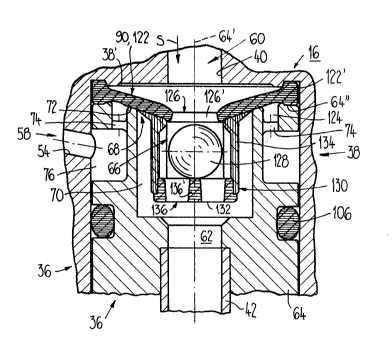
A further embodiment of the safeguard 36 is
illustrated in Figures 12 to 14, said embodiment differ-
ing essentially from the embodiments described above in
that the valve seat of the first valve 66 is arranged in
a stationary manner and the valve body 88 of the first
valve 66 is coupled to the valve body 90 of the second
valve 68. Figure 12 shows the safeguard 36 under normal
operating conditions, whereas in Figure 13 the safeguard
36 is illustrated under conditions allowing backflow.
Figure 14 shows a section along the line XIV-XIV of
Figure 12.
The safeguard 36 is inserted from below in the
further recess 38 of the upper housing part 16 and is
held there by means of a retaining screw 146 which is
screwed into the upper housing part 16 in the radial
direction in relation to the axis 64~ and penetrates said
upper housing part. The retaining screw 146 is of conical
construction at its end facing the safeguard 36 and it
engages in a circumferential retaining groove 146' in the
housing 64 of the safeguard 36. The water fed in through
the feedline 34 (Figure 1) flows from the control cart-
ridge 32 through the passage aperture 40 in the flow
direction S through the safeguard 36 to the pipe 42 which
" 2~37407
- 22 -
is introduced from below into a connection nozzle 148
screwed into the housing 64. The aeration channel 54
leads away from the central region of the further recess
38 obliquely upward through the upper housing part 16 to
the nozzle 48 (cf. Figure 1).
The safeguard 36 has two valves 66, 68, the first
valve 66 being connected in the flow path 60 leading
through the safeguard 36 and the second valve 68 being
connected in the aeration path 58 connecting the flow
path 60 to the ambient air. The second valve 68 is
provided in the flow path 60 at the entry of the aeration
path 58 and is mounted downstream of the first valve 66,
in the flow direction S.
The housing 64 has an essentially cylindrical
housing recess 70 which is open toward the passage
aperture 40 and has the form of a blind hole, in the base
region of which there is constructed an annular valve
seat 72 for the second valve 68. The valve seat 72
borders and bounds an aeration passage 74 which extends
away from the housing recess 70 downward firstly in the
direction of the axis 64' and then in the radial direc-
tion to a circumferential groove 76 provided on the
housing 64, which circumferential groove is connected in
terms of flow to the aeration channel 54. Extending
around the valve seat 72 there is a groove-shaped inden-
tation 78, from which bore holes 80 begin extending in
the direction of the axis 64', which bore holes connect
the housing recess 70 to the outlet opening 62. The
outlet aperture 62 is bounded at the bottom by the
connection nozzle 148.
An annular valve seat element 150, made of
plastic, of the first valve 66 is inserted and held in a
snap-on manner in the passage aperture 40. This valve
seat element 150 interacts with a hemispherical valve
body 88 which has a retaining bolt 152 projec~ing down-
ward. The retaining bolt 152 is pressed into a hole in a
shaft 92 which extends in the direction of the axis 64'.
Seated on the shaft 92 is an annular valve body 90 of the
second valve 68 which is made of rubber-elastic material
2037~7
- 23 -
and has a lip 90' interacting with the valve seat 72. At
its upper end, the annular valve body 90 is in contact
with a step-type taper of the shaft 92 and is held at the
bottom by a holding rib 92~' molded onto the shaft.
Consequently, the valve body 90 is seated fixedly against
displacement on the shaft 92. The lower part 154 of the
shaft 92 projecting over the valve body 90 in the direc-
tion of the axis 64' engages in the aeration passage 74
and is supported on the base 74' of the aeration passage
74 when the valve body 88 is in the operating position.
When the second valve 68 is closed, the position of the
valve body 90 in relation to the valve seat 72 interact-
ing with it is thereby precisely defined.
Provided in the recess 70 in the region between
the housing 64 and the shaft 92 is a flow element 156
which surrounds the shaft 92 in an annular fashion
essentially in the region between the valve body 88 and
the valve body 90, as is also shown in Figure 14. This
flow element 156 is formed from rubber-elastic material
and has a plurality of flow apertures 84 extending in the
direction of the axis 64'. Molded onto the flow element
156 at its inner upper end is a collar 156' which pro-
jects inward in the radial direction and is constructed
so as to be thickened at its free end. The collar 156'
engages between the valve body 88 and the shaft 92 and it
is held on the latter by means of reliefs. Molded onto
the flow element 156 in one piece outside the flow
apertures B4 is a cross-sectionally, U-shaped sealing
member 100 in the shape of a rolled diaphragm which
surrounds the upper end region of the housing 64 and is
held clamped between the housing 64 and the upper housing
part 16 by means of a protrusion 100' engaging in a
circumferential groove 102 in the housing 64.
Provided below the circumferential groove 76 is
an O-ring 106 which bears against the upper housing part
16 and is arranged in a corresponding groove in the
housing 64 of the safeguard 36. Consequently, the circum-
ferential groove 76 is sealed off at the top by the
protrusion 100' of the sealing member 100 and at the
2037~07
- 24 -
bottom by this O-ring 106. A further O-ring 158, which
acts between the housing 64 and the connection nozzle 148
screwed into said housing, seals off the outlet aperture
62 towards the outside.
The mode of functioning of this embodiment of the
safeguard 36 is now described in greater detail with
reference to Figures 12 and 13. Figure 13 shows exactly
the same safeguard 36 as Figure 12, the first valve 66
having closed, however, under conditions allowing back-
flow and the second valve 68 having opened. In Figure 13,
the reference numerals are only included insofar as they
are necessary for understanding the mode of functioning.
Under normal operating conditions, the valve body
88 of the first valve 66 and the valve body 90 of the
second valve 68 are in the operating position shown in
Figure 12. In this case, the first valve 66 is opened and
the lip gor of the second valve body 90 bears against the
valve seat 72. The water fed in in the flow direction S
flows through the flow apertures 84 in the flow element
156 to the bore holes 80 and through the latter into the
outlet apexture 62, from where the water is conducted
through the pipe 42 to the hose 44 and the shower 50. If
the control cartridge 32 upstream of the safeguard 36 i5
closed (Figure l), the valve bodies 88, 90 remain in the
operating position, which results in the second valve 68
remaining closed. This occurs even in the case of rapid
switching-off of the water flow due to closure of the
control cartridge 32. By this means, the emergence of
water through the aeration path 58 is prevented in any
case. If the extremely rare case then occurs that a
negative pressure is built up on the feed side when the
control cartridge 32 is opened, the first valve 66 closes
automatically by the valve body 88 being lifted under the
application of pressure, which is different on the two
sides, to the flow element 56 and the sealing member lO0,
and it is pressed against the valve seat element 150. By
this means, the flow path 60 is interrupted. Water is
thuq prevented from flowing back from the outlet 52 to
the feedline 34. The position of the valve body 88 is
2037~07
- 25 -
shown in Figure 13 with valve 66 closed. Since the valve
body 88 of the first valve 66 is rigidly coupled by means
of the shaft 92 to the valve body 90 of the second valve,
the second valve 68 is inevitably opened by the closure
of the first valve 66. By this means, the outlet 52 is
connected through the aeration path 58 to the
environment.
If water is now fed from the feedline 34 to the
safeguard 36 again, the flow element 156 together with
the two valve bodies 88 and 90 move downward into the
operating position, by which means the first valve 66 is
opened again and the second valve 68 is inevitably
closed.
In all the developments of the safeguard shown,
the first valve can be constructed as a check valve of
any design. In the developments in accordance with
Figures 2-11, the essence of the invention consists in
the fact that, by virtue of the flow conditions in the
flow path under conditions allowing backflow, the first
valve can be brought from an operating position assumed
under normal operating conditions into a backflow posi-
tion and the valve body of the second valve also executes
this movement in order to be inevitably opened. In the
development in accordance with Figures 12-14, the first
valve is closed automatically under conditions allowing
backflow. The closing movement of the corresponding valve
body inevitably opens the second valve.