Note: Descriptions are shown in the official language in which they were submitted.
20376~8
A METHOD FOR RECORDING REMOVAL OF
MATERIAL DURING PRECISION FINISHING
OF PRE-PROFILED WORK PIECES
Background of the Invention
The present invention relates to a method for
recording the removal of material during the
precision fin~hin~ of pre-profiled work pieces,
especially toothings, on a machine tool comprising
a tool, a sensor and a computing device, the tool
preferably being a grinding or polishing tool.
Especially in the aviation industry, profiled
components such as toothings are employed. It is
important that these components not only are a
precisely shaped but are also provided with a layer
of hard materials of a uniform thickness,
especially in load-carrying or stressed areas.
Therefore, during the manufacture of such
components on machine tools, attention must be paid
that during the removal of material with a tool,
preferably a grinding or polishing tool, from a
pre-profiled, hardened work piece a precise profile
shape is achieved and that, on the other hand, a
hardened layer of a required minimum thickness
remains on the surfaces after the machining step.
It is assumed that the pre-profiled work pieces,
that have been hardened before the final machining
step, have a hardened layer of a certain uniform
-- 1 --
2037658
thickness resulting from the respective hardening process employed.
It is therefore an object of the present invention to provide a method
of the ~f~,r~",e"~iulled general kind with which a precise profiling is achieved and a
required minimum hardened layer of a desired thickness is guaranteed.
Summary of the Invention
The invention provides a method for recording removal of material
during precision finishing of pre-profiled work pieces on a machine tool cor"~ i"g
a tool a sensor and a computing device including the steps of: a first measuring
step of measuring a geometric position relative to said tool of at least some points
10 of surfaces to be machined of said pre-profiled work piece with said points being
clldld~ tk for a desired shape of said work piece and ",e",o,i~;"g resulting
first measurements; machining said surfaces of said work piece by removal of
material; a second measuring step of measuring at least said points of said
machined work piece that have been measured in said first measuring step and
",er"o,i~;"y resulting second measurements; c~",~,a,i"g said first and said second
measurements and computing data of effective removal of material at said
positions; outputting said data of effective removal of material for said work piece;
d~l~,l"i";"g in a simulated computation before machining said work piece based
on said first measurements of said pre-profiled work piece values for theoretical
20 ones of said relative positions of said tool to said work piece after said ",a- l,;";"y
comparing said values of said theoretical relative positions with said first
measurements and computing respective machining values for removal of material
during said machining; sorting out ones of said work pieces that require said
respective Illd~;ll;ll;ll9 values to exceed admissible machining limits; performing said
- 2 -
25476-1 51
2037658
",a.,l,i"i"g, said second step of measuring, said Co~ Jd,i"g and computing, and
said outputting on said work pieces not sorted out; measuring in said first
measuring step all of said points of said surfaces to be machined; arld adjusting
said work piece with respect to said ll~eo~ .dl positions such that an average
minimum deviation of said II,eor~,ti~,al positions relative to said first measurements
is achieved.
With the resulting recording of removed
- 2a -
25476-1 51
20376~8
material of at least some points of the surfaces to
be machined of the pre-profiled work piece, with
those points being characteristic for a desired
shape of the work piece, it is ensured, that such
work pieces that have a precise profile but have
been machined such that an intolerable removal of
material has taken place at at least one of the
surfaces, so that a sufficient minimum thickness of
the hardened layer may not be guaranteed, are
sorted out. With the inventive recording it is also
possible to sort out work pieces that have not been
machined properly due to a misadj ustment of the
tool with too much play or tolerance. With a single
clamping step of the work piece onto the machine
tool equipped with a respective tool and a sensor,
a high-precision machining or finishing is
achieved, comprising within a short period of time
an exact determination, based on exact
measurements, of the amount of effectively removed
material, including the determination of the
presence of a minimum thickness of the hardened
layer. The inventive recording of the removal of
material may not only be used to sort out work
pieces with an insufficient hardened layer on at
least one of the machined surfaces but also as
evidence that the work pieces which have been
approved not only have the required precision
-- 3 --
203i7658
proflle and shape but also have at the machlned surfaces a
sufflclent thlckness of the hardened layer. D~r-on~ln~ on the
computer hard ware and soft ware of the comput lng devlce of
the respectlve machlne tool, the recordlng may be provlded ln
the form of tables and/or graphlc dlsplays.
Descrlptlon of Preferred r ~ 5
The present lnventlon wlll now be descrlbed ln
detall wlth reference to the attached drawlngs ln whlch:
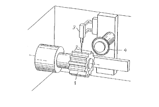
Flgure 1 ls a perspect lve vlew of an apparatus
accordlng to the lnventlon as applled to a toothlng.
Flgure 2 ls a f lowchart of a method accordlng to the
lnvent lon .
In order to avold the tlme consumlng and expenslve
machlnlng of a pre-prof lled work plece when after the f lrst
measurlng process lt ls determlned that the machlnlng of at
least one of the surfaces wlll requlre a removal of materlal
resultlng ln falllng below the mlnlmum requlred thlckness of
the hardened layer, the present lnventlon provldes the
followlng further steps: determlnlng ln a slmulated
computatlon before machlnlng the work plece, based on the
flrst measurements of the pre-proflled work plece, values for
theoret lcal relat lve poslt lons of the tool to the work plece
after the machlnlng7 comparlng the values for the theoretlcal
relatlve posltlons wlth the flrst measurements and computlng
respectlve machlnlng values for removal of materlal durlng the
machlnlng; sortlng out ones of the work pleces that requlre
the respectlve machlnlng values to exceed admlsslble machlnlng
llmlts; performlng r~-hln1n~, the second step of measurlng,
-- 4 --
~1 25476-151
~4
2037658
comparlng and comput lng, and outputt lng on the work pleces not
s o rt ed out .
Wlth thls lnventlve: o~lr- lt ls posslble to
determlne the quallty of the flnlshed product before the
actual machlnlng step takes place, based on the measurements
taken of the pre-proflled work plece. Should lt be lmposslble
to produce a f lnlshed product of the requlred quallty
standards, for example, due to unavoldable deformatlons durlng
the hardenlng step, the respectlve work plece ls sorted out,
result lng ln reduced machlnlng t lme and reduced machlnlng and
t oo 1 cost .
Flgure 1 shows a gear wheel 1 whlch ls measured at
lts functlonal polnts, namely the teeth surfaces, wlth ald of
the measurlng sensor 2 of a measurlng lnstrument 3. The
measured values are memorlzed.
The gear wheel 1 ls subsequent ly f lnlshed wlth ald
of a grlndlng dlsk 4, l.e. on all surfaces to be ~~~h1nl~c
After completlon of thls flnlshlng process, the
f lnlshed gear wheel 1 ls measured agaln, at least at the
polnts measured ln the f lrst procedural step. These values
are also memorlzed.
The values measured prlor to and after the flnlshlng
are now compared and the effectlve removal of materlal
computed at the measured polnts. The computed data for the
removal of materlal are now recorded for each lndlvldual work
plece and attached to the f lnlshed work plece ln sultable
form, so that the documentatlon produced provldes the
purchaser of the gear wheel 1 wlth proof that lt was duly
-- 5
25476-151
A
2037658
flnlshed at all functlonal polnts, ln partlcular wlth respect
to the fact that an adequately large hardened layer was
malntalned .
Flgure 2 agaln lllustrates the method of the
lnvent lon by descrlblng the steps lnvolved .
In a preferred . '1- , the geometrlc posltlon of
all the polnts of the surfaces to be machlned are measured ln
the f lrst measurlng step and the work plece ls then ad~usted
wlth respect to the theoretlcal posltlons such that an average
mlnlmum devlatlon of the theoretlcal posltlons relatlve to the
f lrst measurements ls achleved ( stock dlvldlng), whereby lt ls
ensured that at the polnt wlth the smallest devlat lon of the
flrst measurement from the theoretlcal posltlons a mlnlmum
removal of materl~l ls carrled out.
Wlth the descrlbed lntegratlon of the known
- 5a -
25476-151
, _
2~37658
stock dividing method into the method of the
present invention, the machining expenditure due to
material removal may be minimized while at the same
time it may be possible, by adjusting the
theoretical zero position of the work piece, to
reduce the removal of material at a position with
a surface having a critically thin hardened layer
to such an amount that a work piece usually
considered to be below the quality standards may be
finished to yield a quality product. Since the
machine tool is already provided with a sensor
having the necessary hard and soft ware, in most
cases it is sufficient to upgrade the soft ware in
order to enable a respective machine tool to
perform the described method of stock dividing and
to realize the respective advantages of minimizing
the removal of material and decreasing the
machining time as well as reducing the amount of
rejected work pieces.
With the present invention, a method for
recording removal of material during the precision
finishing of work pieces that must be of an
extremely precise shape and must withstand extreme
stress, as required especially in the aviation
industry, is provided which ensures that the work
piece has a hardened layer of a required minimum
thickness at all stressed or load-carrying
20376~
positions .
The present invention is, of course, in no way
restricted to the specif ic disclosure of the
specification, examples and drawings, but also
encompasses any modifications within the scope of
the appended claims.