Note: Descriptions are shown in the official language in which they were submitted.
~~i~ ~ r~na~
-1- 21-56(10721)A
LOW FRICTION TRUNNION BEARING AND HIGH PRESSURE SEAL
Background of the Invention and Prior Art
This invention relates generally to fluid
level sensing systems and particularly to systems in
which the sensed fluid is in a vessel or tank under
high pressure.
In general prior art systems sense changes in
the level of a liquid in a tank or other container with
a sensing element or float that is in communication
with the liquid in the container and which transmits a
force or movement to a control device that is situated
outside the container. The force or displacement is a
measure of the change in liquid level. For lov
pressure installations, the seal between the container
and the means that transmit the force or motion from
the sensor inside the container to the control means
outside the container may be relatively simple. For
example, a simple bellows would suffice. For high
pressure environments, however, the type of seal is
critical. In such an arrangement, pressures up to
6,000 Ibs. per square inch (~d22 kilograms per square
centimeter) may be encountered. Further, the means for
relaying the force or motion should be capable of
providing reliable and consistent operation in a
variety of different environments. Also the friction
imposed by the bearing and the seal should be minimal
and uniform for different applications. In particular,
the friction in the mechanism should be insensitive to
the high pressure within the tank.
One prior art seal is shown in tl.S. Patent
No. 4,700,738 in which motion is transmitted by a
rotatable shaft. An 0-ring effects a seal between the
shaft and the housing. The rotational type seal
introduces a significant amount of friction and
requires a breakout torque to begin operation which
adversely affects the accuracy of the sensing
mechanism. The amount of friction is also dependent
-2- 21-56(10721)A
upon the pressure applied to the seal.
The device illustrated in U.S. Patent
No. 4,838,303 transmits a rocking motion through the
seal which flexes with movement of the transmitting
shaft. The plane of the motion is defined by a single
point fulcrum and a guiding mechanism. Significant
friction is encountered when sliding occurs between the
pin and the guiding mechanism. Also the seal may not
be serviced without completely~removing the sensor body
from its mounting.
The trunnion bearing and seal of the present
invention not only satisfies the above mentioned
criteria, but has an important advantage of being field
serviceable. The bearing and seal are easily removable
to permit seal renewal or general maintenance. The
trunnion bearing and high pressure seal of the
invention also provides a replaceable low friction,
high pressure liquid level sensor arrangement. The
inventive apparatus consists of a pivot disk that is
connected to a displacer arm (and sensor element) at
one end and to a control arm (and controller) at the
other end. A removable end cap carries a pair of pivot
pins that are engageable with a pair of spherically
shaped depressions in the face of the pivot disk. The
control arm freely passes through an orifice in the end
cap and is spring loaded (against the end cap) to
maintain the pivot disk in engagement with the pivot
pins. An elastomeric seal is prav9.ded between the end
cap and a movable spacer and between the movable spacer
and the pivot disk for permitting slight movement of
the pivot disk about the pivot pins without disruption
of the high pressure seal.
Objects of the Invention
A prinoipal object of the invention is to
provide an improved high pressure fluid level sensor
system.
Another object of the invention is to provide
I~~'
-3- 21-56(10721)A
a novel high pressure fluid level sensor that is
readily replaceable in the field.
A further object of the invention is to
provide a novel low friction bearing and seal
arrangement for transmitting small movements from a
sensor located in a high pressure area to a controller
located in a low pressure area.
_B_ri_ef Description of the Drawings
These and other objects and advantages of the
invention will be apparent upon reading the following
description in conjunction with the drawings, in which:
FIG. 1 shows the sensor movement-responsive
elements of a controller including a relay module, as
used with the preferred embodiment of the invention;
FIG. 2 is a partial section taken along the
line 2-2 of FIG. 1 showing the trunnion bearing and
seal of the invention in a high pressure liquid level
sensor environment;
FIG. 3 is an end view of the pivot disk of
the invention;
FIG. 4 is a sectional view taken along the
line 4-4 of FIG. 3;
FIG. 5 is an end view of the end cap of the
trunnion;
FIG. 6 is a sectional view taken along the
line 6-6 of FIG. 5;
FIG. 7 is an end view of the body that houses
the trunnion bearing;
FIG. 8 is a sectional view taken along the
line 8-8 of FIG. 7;
FTG. 9 is a partial view in the direction
indicated by the arrow A in FIG. 2 showing the pivot
pin arrangement; .
FIG. 10 is a sectional view taken along the
line 10-10 of FIG. 9;
FIG. 11 is a sectional view of the spacer
used in the seal of the invention;
-4- 21-56(10721)A
FIG. 12 is an end view of the spacer of FIG.
11; and
FIGS. 13 and 14 are end and side views,
respectively, of a pivot pin used in the invention.
Description of the Preferred Embodiment
Referring to FIG. 1, a controller 10 has a
base 11 and includes a relay module 12 having a motion
responsive input device 14 that may comprise a pin that
is actuated by means of a pair of pivotally mounted
input and output levers 16 and 18. Input lever 16 has
a flat portion 19 over which a spring clip type fulcrum
is movably mounted. An end 21 of input lever 16 is
formed to engage the end of a control arm 22. As will
be seen, control arm 22 is coupled to a sensing
15 mechanism for determining the level of a liquid in a
tank. Input lever 16 is pivotally mounted to base 11
by means of a pivot l5 and output lever 18 is similarly
pivotally mounted by means of a pivot pin 17. By
moving the spring clip fulcrum 20 along flat portion '
20 19, the force application point between input lever 16
and output lever 18 may be changed. Consequently the
amount of movement of output lever 18 in response to
movement of input lever 16 may ba varied.
A zero adjustment mechanism comprises a coil
spring 24 having a hooked end 25 engaging a groove or
bend in the end of control arm 22. The other end of
spring 24 engages a seating plate 26 that includes a
threaded aperture. A bolt 28 is screwed into the
threaded aperture in seating plate 26 and extends
through a support post 27 which is integral with the
base 11 of controller 10. A wing nut 30 is provided
for adjusting the force exerted by spring 24 and a lock
nut 32 secures the adjustment position. A pair of
gauges 34 and 36 provide suitab Ie information to the
operator and four mounting bolts 38 secure the
controller base l1 to an end cap of the trunnion body,
as will be seen with reference to FIG. 2.
-5- 21-56(10721)A
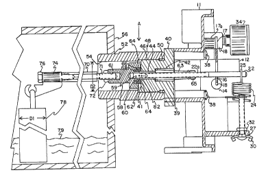
FIG. 2 discloses a side sectional view
through the trunnion body, bearing and seal of the
invention, the controller body and portions of the
sensing mechanism and high pressure tank. A removable
end cap 40 is secured in sealing relationship to base
11 of controller 10 by a suitable gasket 39 and
mounting bolts 38 whic'n engage corresponding threaded
apertures (visible in FIG. 5) in end cap 40. The end
cap 40 has a generally T shaped cross section and
includes an external threaded portion 46 for threaded
engagement with a similar internal threaded portion on
trunnion body 48. A first cylindrical recess 42 opens
into a second, smaller cylindrical passageway 44 in end
cap 40. Control arm 22 has a long threaded portion 22a
which freely passes through cylindrical recess 42 and
passageway 44. Body 4$ is also generally cylindrical
and includes an annular bore 54 of a diameter D2 that,
as mentioned, has a complementarily threaded portion at
one end for engaging threaded portion 46 of end cap 40.
An 0-ring 50 provides a seal between body 48 and end
cap 40. The other end of body 48 has an external
threaded portion 52 that engages a suitable orifice in
a high pressure tank 56, depicted in broken
configuration to show the relevant sensor elements.
A pivot disk element 58 of stepped
cylindrical configuration includes a centrally
disposed, threaded blind hole 59 in which the end of
threaded portion 22a of control arm 22 is secured to
rigidly attach pivot disk 58 to control arm 22. The
other end of pivot disk 58 includes another threaded
blind hole 61. An annular recess 60 is formed in the
large face of pivot disk 58 and is adapted to receive a
ring -shaped spacer 62 having a stepped cross section.
As will be seen in more detail with reference to
FIG, 4, a raised cylindrical collar 82 is situated in
the center of pivot disk 58 and forms an inner (smaller
diameter) wall of annular recess 60, the outer (larger
~~~~1''lj~
-6- 21-56(107z1)A
diameter) wall of recess 60 being parallel thereto.
Spacer 62 engages collar 82 and the outer wall of
annular recess 60 in a slip fit and is therefore
axially movable with respect to these parallel walls.
One end of spacer 62 is adapted to engage a seal
surface 41 formed on the bottom of end cap 40. An 0-
ring 64 seals the end of spacer 62 and the seal surface
41 on end cap 40 and a pair of 0-rings 66 and 6$ seal
the spacer 62 to the pivot disk 5$. A compression
spring 63 is seated in the bottom of cylindrical recess
42 in end cap 40 and affixed to control rod 22 by means
of an adjustment nut 65 that is movable along threaded
portion 22a. Compression spring 63 forces pivot disk
58 toward end cap 40. As best seen by reference to
FIG. 9, a pair of pivot pins limit the travel of pivot
disk 5$ and are loaded by the action of spring 63.
A displaces arm 70 includes a threaded end 71
which engages the threaded blind hole 61 of pivot disk
5$ and is secured in the desired position by means of a
lock nut 72. The other end of displaces arm 70 is
coupled to a support 74 that is secured to the other
end of displaces arm 70 by a suitable nut 76. Support
74 is rotationally movable on displaces arm 70,
however. A displaces or float element 78, preferably
cylindrical in shape and of a diameter D1 that is
smaller than diameter D2 in body 48, is partially
immersed in a fluid such as a liquid 79 and supported
by support 74. As will be seen, vertical movement of
element 78 in response to changes in buoyant force
exerted thereon responsive to changes in the level of
liquid 79 cause displaces arm 70 to move vertically.
This results in an upward (or downward) movement of
pivot disk 58. Pivot disk 58 engages the pair of pivot
pins and is restricted to pivotal movement about a
pivot axis defined by a line perpendicular to the
drawing and passing through point "0°'. Movement of
pivot disk 58 about this pivot axis causes a
;;J
v ~
-7- 21-56(10721>A
proportional opposite movement of control arm 22. The
provision of a cylindrical displaces element 78, of
smaller diameter than the diameter D2 of body 48,
enables removal of the displaces element through the
body 48.
FIGS. 3-8 show plan and sectional views of
pivat disk 58, end cap 40 and body 48. With particular
reference to FIGS. 3 and ~+, pivot disk 58 includes
centrally disposed cylindrical collar 82 that extends
beyond the surface in which annular recess 60 is
formed. A pair of spherical or cup-shaped depressions
80 and 81 are formed in the outer face of pivot disk 58
for cooperation with the pair of pivot pins as will be
described.
In FIGS. 5 and 6, end cap 40 has an outer
configuration that is adapted to be engaged by a wrench
or the like for screwing end cap 40 into and out of
body 48. Four threaded holes 84 are formed in the
large face of end cap 40 for enabling corresponding
bolts 38 to secure the controller base 11 to end cap
40. The smaller end of end cap 40 includes seal
surface 41 and a pair of blind holes 86 and 88 in which
tha pivot pins are secured:
FIGS. 7 and 8 show the cylindrical body 48.
Body 48 also has an exterior that is engageable by a
wrench for facilitating installation of the body in a
suitably threaded orifice in a high pressure tank.
FIG: 9 is a sectional view of the trunnion
and seal arrangement of FIG. 2 viewed in the direction
of arrow A. In this view, a pair of pivot pins 90 and
92 are clearly shown with their points engaging
depressions 80 and 81, respectively. Pivot pins 90 and
92 are secured in recesses 86 and $8, respectively,
that are formed in the bottom of end cap 40. Annular
35' spacer 62, as best shown in FIG. 11, has a generally
stepped cross section and has an outer wall 75 that
forms a slip fit with the larger diameter wall of
-8- 21-56(10721)A
annular recess 60 in pivot disk 58. Its inner wall 77
also forms a slip fit with collar 82 of pivot disk 58.
Consequently, spacer 62 is free to move into and out of
annular recess 60. The pair of 0-rings 66 and 68 seal
spacer 62 to pivot disk 58 arid the 0-ring 64 seals
spacer 62 to seal surface 41 on end cap 40.
In operation, the adjustment spring 24 is
adjusted by means of wing nut 30 to zero the control
arm displacement for the particular sensor
installation. Thereafter, changes in buoyant force
applied to element 78 are reflected in vertical
displacement of displaces arm 70 which causes pivot
disk 58 to pivot about the pivot axis "0" defined by
the points of the pivot pins 90 and 92. The small
movement is accommodated by spacer 62 being axially
displaced along collar 82 and the outer wall of the
annular recess 60 against the urging of the resilient
0-rings 64, 66 and 68. The design enables a very high
pressure seal to be maintained through the trunnion
bearing. The trunnion bearing and seal arrangement
exhibits extremely low friction which is not
substantially affected by the pressure encountered from
the high pressure tank. The body 48, end cap 40, pivot
disk 58 and spacer 62 are all fabricated of metal, the
only elastomeric materials being the 0-rings 64, 66 and
68.
An important feature of the invention is easy
serviaability. Body 48 is secured to high pressure
tank 56 and need not be removed, nor the sensor
components in the tank removed in the event that
maintenance or replacement of the seals is required.
Servicing is accomplished by removing the four
retaining bolts 38 holding body 11 to end cap 40. End
cap 40 may simply be unscrewed to remove it from body
48 without disengaging the pivot disk 58 from pivot
pins 9Q and 92 because displaces arm 70 is rotatable in
support 74. Indeed, because of the relationship of the
-9- 21-56(10721)A
diameter D1 of element 7$ and the diameter D2 of body
48, the entire assembly (end cap 40; 0-rings, spacer
62, pivot disk 58, displaces arm 70, element 78,
control arm 22 and spring 63) may be removed as a unit
for servicing. Alternatively, pivot disk 58 may be
"unloaded" by forcing control arm 22 to the left,
either by physically pushing on the arm or by releasing
the force exerted by spring 63 by turning adjusting nut
65 along threaded portion 22a of the control arm, to
permit removal of end cap 40. (Forcing the pivot disk
58 to the left disengages the pivot disk 58 from pivot
pins 90 and 92 and permits end cap 40 to be unscrewed
from body 48.) Thereafter pivot disk 58, which is
attached to control arm 22, may be withdrawn to permit
servicing of the seals and/or adjustment of the length
of displaces arm 70. This may be accomplished without
removal of the sensor components or body from the high
pressure tank.
What has been described is a novel low
friction, high pressure trunnion bearing and seal. It
is recognized that numerous changes in the described
embodiment of the invention will be apparent to those
skirled in the art without departing from its true
spirit and scope. The invention is to be limited only
as defined in the claims.