Language selection

Search

Patent 2037895 Summary

Third-party information liability

Some of the information on this Web page has been provided by external sources. The Government of Canada is not responsible for the accuracy, reliability or currency of the information supplied by external sources. Users wishing to rely upon this information should consult directly with the source of the information. Content provided by external sources is not subject to official languages, privacy and accessibility requirements.

Claims and Abstract availability

Any discrepancies in the text and image of the Claims and Abstract are due to differing posting times. Text of the Claims and Abstract are posted:

  • At the time the application is open to public inspection;
  • At the time of issue of the patent (grant).
(12) Patent: (11) CA 2037895
(54) English Title: SAFETY RAZORS
(54) French Title: RASOIRS DE SURETE
Status: Expired and beyond the Period of Reversal
Bibliographic Data
(51) International Patent Classification (IPC):
  • B26B 21/18 (2006.01)
  • B26B 21/22 (2006.01)
  • B26B 21/56 (2006.01)
(72) Inventors :
  • BROWN, FRANK EDWARD (United Kingdom)
  • TAYLOR, JOHN (United Kingdom)
  • WILKES, DAVID JOHN (United Kingdom)
(73) Owners :
  • THE GILLETTE COMPANY
(71) Applicants :
  • THE GILLETTE COMPANY (United States of America)
(74) Agent: MACRAE & CO.
(74) Associate agent:
(45) Issued: 1998-07-07
(86) PCT Filing Date: 1990-07-10
(87) Open to Public Inspection: 1991-01-25
Examination requested: 1993-11-17
Availability of licence: N/A
Dedicated to the Public: N/A
(25) Language of filing: English

Patent Cooperation Treaty (PCT): Yes
(86) PCT Filing Number: PCT/US1990/003863
(87) International Publication Number: WO 1991001204
(85) National Entry: 1991-03-25

(30) Application Priority Data:
Application No. Country/Territory Date
8916885.0 (United Kingdom) 1989-07-24

Abstracts

English Abstract


A safety razor in which the blade (1) has a plurality of sharp-edge apertures (2) for shaving and also a sharpened rectilinear
edge (3) for trimming. Provision is made for effecting displacement of the blade relative to the razor handle (10) so that the
trimming edge which is normally in an inoperative position can be moved into an operative position. The blade is held in an
arched position so that the aforesaid movement is of a rocking nature.


French Abstract

Rasoir de sûreté dont la lame (1) comporte une pluralité d'ouvertures (2) à bord tranchant pour effectuer le rasage, ainsi qu'un bord rectiligne (3) pour effectuer les coupes droites. Un mécanisme permet le mouvement de la lame par rapport au manche (10) du rasoir, afin que le bord rectiligne puisse passer d'une position normalement inopérante à une position opérante. La lame est maintenue dans une position arquée, ce autorise le mouvement basculant mentionné ci-dessus.

Claims

Note: Claims are shown in the official language in which they were submitted.

THE EMBODIMENTS OF THE INVENTION IN WHICH AN EXCLUSIVE PROPERTY
OR PRIVILEGE IS CLAIMED ARE DEFINED AS FOLLOWS:
1. A safety razor comprising a perforated blade (1)
having a plurality of sharp edged apertures (2) distributed over
its surface, said blade (1) being mounted in a foil carrier (5),
characterized in that the razor further comprises sharpened,
straight continuous trimming edge means (3, 31A); and,
wherein said edge means is formed on a perimeter of
said blade (1).
2. A safety razor comprising a perforated blade (1)
having a plurality of sharp edged apertures (2) and mounted in
a foil carrier (5), characterized in that the razor further
comprises sharpened, straight trimming edge means (3, 31A); and
wherein said edge means is formed on a perimeter of said blade
(1) said razor also comprising:
a support (6) on which said foil carrier (5) is
mounted; and
said foil carrier (5) being operably displaceable with
respect to said support (6);
whereby, said edge means (3, 31A) is normally
inaccessible for use and is selectively brought into orientation
by displacement of the foil carrier (5) relative to said
support (6).

3. A safety razor according to claim 2, characterized
in that said support includes a guard member (7) which normally
obscures the edge means (3), and that the carrier (5) is
disposable, relative to the support (6), to expose the edge
means (3).
4. A safety razor according to claim 3, characterized
in that the carrier (5) is connected to the support (6) in a
bi-stable manner to occupy either of two operative positions,
means being provided for resiliently detaining the carrier (5)
in each position relative to the support (6).
5. A safety razor according to claim 3, characterized
in that the blade (1) is held in an arched condition in the
carrier (5) and that the support (6) is mounted on a handle (10)
for rocking movement about a horizontal axis (C) parallel with
the axis of curvature of the blade (1) and that indexing means
(14) are provided for selectively retaining the support (6) at
an extreme position in its range of rocking movement.
6. A safety razor according to claim 2, characterized
in that said foil carrier (5) is mounted on a handle (10) for
movement between a position of normal use in which the edge means
is substantially inaccessible for use, and an extreme position
in which the edge means is presented in a position of use.

7. A safety razor according to claim 6, characterized
in that the foil carrier (5) supports the blade member (1) in an
arched condition and is mounted on the handle for rocking
movement about an axis parallel with the axis of curvature of the
blade (1), the carrier being displaceable into said extreme
position in which it is held against rocking movement and in
which the edge means (31A) is presented for use.

Description

Note: Descriptions are shown in the official language in which they were submitted.


CA 0203789~ 1998-03-23
Safety Razors
This invention relates to safety razors, more particularly
in which a blade member is in the form of a foil having a
plurality of sharp edged apertures distributed over its surface
to constitute a plurality of discrete cutting edges. Such blade
members are referred to in the following description as
"perforated blades".
In accordance with the invention, there is provided a
safety razor comprising a perforated blade mounted in a foil
holder and having a sharpened, rectilinear trimming edge means.
Preferably, the said edge means is normally inaccessible
for use but can be brought into operation by effecting
displacement of at least a part of the foil holder relative to
the razor handle.
The razor can accordingly operate normally as a perforated
blade razor, typically being employed with a reciprocating,
"scrubbing" action, but the sharpened edge means can be brought
into use as required for trimming operations, such as the
trimming of sideburns or moustaches.
Some forms of razor in accordance with the invention are
described in detail below, by way of example, with reference to
the accompanying drawings, in which:-
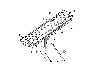
Figs. 1 and 2 are perspective views of a razor with its
parts adjusted into a shaving mode and a trimming mode,
respectively;
Figs. 3, 4 and 5 are sectional views showing the razor
parts in a normal shaving mode, a fixed position and the
trimming mode, respectively;
Fig. 4A is a scrap detail view taken in the direction of
arrow 'A' in Fig. 4;
Fig. 6 is a perspective view of the head of a second form
of razor;
Figs. 7 and 8 are sectional views showing parts of the
second razor in its normal and trimming positions, respectively;
Figs. 9 and 11 show a third form of a razor in its
different operative positions; and
Figs. 10 and 12 are scrap views illustrating details of the
sg/~,~

CA 0203789~ 1998-03-23
razor of Figs. 9 and 11.
The razor shown in the drawings comprises a perforated
blade 1 in the form of a foil having sharp-edged apertures 2
distributed over its surface and having one longitu~; n~l edge
sharpened to form a trimming edge 3.
The blade is attached to a foil carrier 5 mounted in turn
on a support 6 including a guard member 7 and depending lugs 8
by which the support 6 is mounted on cams 9 fast with the razor
handle 10.
The support 6 is mounted on the handle in a manner which
permits free, rocking movement of the support, relative to the
handle, about an axis parallel with the trimming edge 3. This
is conveniently provided by means of a pair of stationary,
arcuate cams 9 fast with the handle, which engage in arcuate
grooves in the lugs 8 of the support. The centre of curvature
of the cams and grooves is disposed close to the surface of the
foil, for example at the axis 'C' indicated in the drawings.
The carrier has a range of free, rocking movement during
normal shaving to permit additional conformance of the foil to
the skin contours. However, to expose the trimmer edge, the
support must first be latched into its fixed position, shown in
Fig. 4, at one end of its range of rocking movement. For this
purpose, a latch projection 14 is formed on one or both lugs 8
for co-operation with an adjacent portion on the cam 9. As best
seen in Fig. 4A, the latch projection 14 takes the form of a
triangular fillet which presents a stop to free rocking movement
of the support in normal use of the razor. However, the user
can apply some manual effort to force the cam to spring past the
projection 14 into the position shown in Fig. 4.
The support 6 includes a platform section 11 fast with the
remainder of the support and onto which the foil carrier is
clipped in a bi-stable manner. In the "normal" and "fixed"
positions shown in Figs. 3 and 4, the platform 11 is fully
engaged in a channel formed in the underside of the foil
carrier. However, due to the resilience of the parts, the
carrier can be displaced angularly relative to the support, to
the position shown in Fig. 5, in which the forward (left-hand)
sgl~u

CA 0203789~ 1998-03-23
edge of platform section 11 has snapped past a detent projection
13 formed on the foil carrier. This exposes the sharpened edge
for trimming, with the foil carrier and support in fixed
position.
To summarise: the razor is normally in the condition
illustrated in Figs. 1 and 3, in which the edge 3 is safely
obscured and the support 6 and foil carrier 5 can rock as one
about the axis C relative to the handle;
by deliberate m~n~l~l displacement applied through the
carrier 5, the carrier and support can be moved into the
position shown in Fig. 4, in which the edge 3 is still concealed
but the support is held stationary on the handle;
further manual effort applied in the same direction causes
the carrier 5 to spring into the position illustrated in Figs. 2
and 5, exposing the edge 3 for use;
reversal of the above procedure will first restore the
carrier 5 to its normal position relative to the support and
guard, and then release the support for rocking movement about
the axis C.
It will be noted that the latch projection 14 is
asymmetrical in its form so as to present less resistance to
movement of the support into the extreme position of Fig. 4 than
in the reverse direction. Also, it is designed to present less
resistance to relative motion than the catch projection 13 in
one direction than in the other, so that a smaller effort is
required to return the carrier to its normal position than to
return the support to its normal position.
Although movement of the parts into the position shown in
Fig. 4 is primarily intended as a prelude to exposing the
trimming edge, the razor is perfectly operable as a "fixed head"
razor in that condition.
The above described razor may be designed as a disposable
razor, in which case the support 6 is permanently associated
with the handle. Alternatively, the support may be releasably
mounted on the handle cams, or the foil carrier (and foil) may
be releasably mounted on the support so that the foil and foil
carrier, with or without the support, can form exchangeable
Sg/ii

CA 0203789~ 1998-03-23
-- 4
blade cartridges.
In the embodiment illustrated in Figures 6, 7 and 8, the
perforated blade 1 has, in addition to the apertures 2 provided
for normal shaving, a row of elongated apertures 31 positioned
adjacent one edge of the foil. The inner edges of these
apertures are sharpened to form a series of aligned, rectilinear
trimming edges 3lA.
In this razor, there is no movable guard to conceal the
trimming edges in normal use of the razor. Instead, they are
simply positioned so as to be held clear of the skin in the
normal range of attitudes of the blade relative to the handle.
The foil holder 5 is again supported on the cam 9 so as to
have a range of rocking movement in normal use of the razor, to
either side of the medial position shown in Fig. 7. When it is
desired to bring the trimming edges into play, the foil holder
is rocked in a clockwise sense, as viewed in Fig. 7, to force
the cam to spring past the latch projection 14, to lock the foil
holder 5 in the position shown in Fig. 8, in which the trimming
edges 31A are positioned "high up" at the leading side of the
blade foil.
The razor shown in Figs. 9 and 10 is generally similar to
that of Figs. 6 to 8 except for the means of latching the foil
holder in the trimming position. In this embodiment, the handle
is fitted with a m~nll~lly actuated sliding latch comprising rod
20 slidably mounted in a slot 21 in the handle and an external
operating button 22. The rod has a pair of rounded ribs 23 at
its lower end and the sides of the slots are formed with upper
and lower pairs of recesses 24, 26 for co-operation with the
ribs.
The latch is shown in Fig. 9 in its lower, retracted
position, where it is held by engagement of.the ribs 23 in the
lower pair of recesses 24, and in which the foil holder 5 is
free to rock for normal shaving. For trimming operation, the
latch is pushed to its upper, extended position. The upper end
of the rod engages the underside of the foil holder 5 and rocks
the holder clockwise to its extreme position, as shown in
Fig. 11. The parts are all held in this position by engagement
sg/~

CA 02037895 1998-03-23
of the ribs 23 in the upper pair of recesses 26, as shown in
Fig. 12.
Upon manual return of the latch to its lower position, the
foil holder is a~ain free to rock.
~/D

Representative Drawing
A single figure which represents the drawing illustrating the invention.
Administrative Status

2024-08-01:As part of the Next Generation Patents (NGP) transition, the Canadian Patents Database (CPD) now contains a more detailed Event History, which replicates the Event Log of our new back-office solution.

Please note that "Inactive:" events refers to events no longer in use in our new back-office solution.

For a clearer understanding of the status of the application/patent presented on this page, the site Disclaimer , as well as the definitions for Patent , Event History , Maintenance Fee  and Payment History  should be consulted.

Event History

Description Date
Inactive: IPC from MCD 2006-03-11
Time Limit for Reversal Expired 2000-07-10
Letter Sent 1999-07-12
Grant by Issuance 1998-07-07
Inactive: Final fee received 1998-03-23
Pre-grant 1998-03-23
Inactive: Received pages at allowance 1998-03-23
Notice of Allowance is Issued 1997-09-24
Letter Sent 1997-09-24
Inactive: Status info is complete as of Log entry date 1997-09-22
Inactive: Application prosecuted on TS as of Log entry date 1997-09-22
Inactive: IPC removed 1997-08-12
Inactive: First IPC assigned 1997-08-12
Inactive: IPC assigned 1997-08-12
Inactive: Approved for allowance (AFA) 1997-08-11
All Requirements for Examination Determined Compliant 1993-11-17
Request for Examination Requirements Determined Compliant 1993-11-17
Application Published (Open to Public Inspection) 1991-01-25

Abandonment History

There is no abandonment history.

Maintenance Fee

The last payment was received on 1998-06-26

Note : If the full payment has not been received on or before the date indicated, a further fee may be required which may be one of the following

  • the reinstatement fee;
  • the late payment fee; or
  • additional fee to reverse deemed expiry.

Please refer to the CIPO Patent Fees web page to see all current fee amounts.

Fee History

Fee Type Anniversary Year Due Date Paid Date
MF (application, 7th anniv.) - standard 07 1997-07-10 1997-06-30
Final fee - standard 1998-03-23
MF (application, 8th anniv.) - standard 08 1998-07-10 1998-06-26
Owners on Record

Note: Records showing the ownership history in alphabetical order.

Current Owners on Record
THE GILLETTE COMPANY
Past Owners on Record
DAVID JOHN WILKES
FRANK EDWARD BROWN
JOHN TAYLOR
Past Owners that do not appear in the "Owners on Record" listing will appear in other documentation within the application.
Documents

To view selected files, please enter reCAPTCHA code :


To view images, click a link in the Document Description column. To download the documents, select one or more checkboxes in the first column and then click the "Download Selected in PDF format (Zip Archive)" or the "Download Selected as Single PDF" button.

List of published and non-published patent-specific documents on the CPD .

If you have any difficulty accessing content, you can call the Client Service Centre at 1-866-997-1936 or send them an e-mail at CIPO Client Service Centre.


Document
Description 
Date
(yyyy-mm-dd) 
Number of pages   Size of Image (KB) 
Abstract 1997-06-18 1 10
Description 1998-03-23 5 214
Claims 1997-06-18 3 75
Cover Page 1993-11-20 1 13
Abstract 1993-11-20 1 9
Drawings 1993-11-20 7 140
Claims 1993-11-20 2 59
Description 1993-11-20 5 189
Description 1997-06-18 5 205
Claims 1998-05-25 3 75
Abstract 1998-05-25 1 10
Description 1998-05-25 5 214
Cover Page 1998-07-04 1 40
Representative drawing 1998-07-04 1 10
Commissioner's Notice - Application Found Allowable 1997-09-24 1 164
Maintenance Fee Notice 1999-08-09 1 179
Correspondence 1998-03-23 6 242
Correspondence 1998-03-23 1 35
Correspondence 1997-09-23 1 95
Fees 1995-06-29 1 60
Fees 1996-06-27 1 59
Fees 1994-06-28 1 67
Fees 1993-07-02 2 89
Fees 1992-06-11 1 19
Prosecution correspondence 1991-03-25 9 371
PCT Correspondence 1991-08-28 1 26
Courtesy - Office Letter 1993-12-30 1 29
Prosecution correspondence 1993-11-17 1 23
Prosecution correspondence 1996-11-18 2 53
Prosecution correspondence 1997-05-09 1 37
International preliminary examination report 1991-03-25 1 42
Examiner Requisition 1996-09-23 2 65
National entry request 1991-04-22 4 146
National entry request 1991-03-25 3 98