Sélection de la langue

Search

Sommaire du brevet 2037895 

Énoncé de désistement de responsabilité concernant l'information provenant de tiers

Une partie des informations de ce site Web a été fournie par des sources externes. Le gouvernement du Canada n'assume aucune responsabilité concernant la précision, l'actualité ou la fiabilité des informations fournies par les sources externes. Les utilisateurs qui désirent employer cette information devraient consulter directement la source des informations. Le contenu fourni par les sources externes n'est pas assujetti aux exigences sur les langues officielles, la protection des renseignements personnels et l'accessibilité.

Disponibilité de l'Abrégé et des Revendications

L'apparition de différences dans le texte et l'image des Revendications et de l'Abrégé dépend du moment auquel le document est publié. Les textes des Revendications et de l'Abrégé sont affichés :

  • lorsque la demande peut être examinée par le public;
  • lorsque le brevet est émis (délivrance).
(12) Brevet: (11) CA 2037895
(54) Titre français: RASOIRS DE SURETE
(54) Titre anglais: SAFETY RAZORS
Statut: Réputé périmé
Données bibliographiques
(52) Classification canadienne des brevets (CCB):
  • 30/27
(51) Classification internationale des brevets (CIB):
  • B26B 21/18 (2006.01)
  • B26B 21/22 (2006.01)
  • B26B 21/56 (2006.01)
(72) Inventeurs :
  • BROWN, FRANK EDWARD (Royaume-Uni)
  • TAYLOR, JOHN (Royaume-Uni)
  • WILKES, DAVID JOHN (Royaume-Uni)
(73) Titulaires :
  • THE GILLETTE COMPANY (Etats-Unis d'Amérique)
(71) Demandeurs :
(74) Agent: MACRAE & CO.
(74) Co-agent:
(45) Délivré: 1998-07-07
(86) Date de dépôt PCT: 1990-07-10
(87) Mise à la disponibilité du public: 1991-01-25
Requête d'examen: 1993-11-17
Licence disponible: S.O.
(25) Langue des documents déposés: Anglais

Traité de coopération en matière de brevets (PCT): Oui
(86) Numéro de la demande PCT: PCT/US1990/003863
(87) Numéro de publication internationale PCT: WO1991/001204
(85) Entrée nationale: 1991-03-25

(30) Données de priorité de la demande:
Numéro de la demande Pays / territoire Date
8916885.0 Royaume-Uni 1989-07-24

Abrégés

Abrégé français

Rasoir de sûreté dont la lame (1) comporte une pluralité d'ouvertures (2) à bord tranchant pour effectuer le rasage, ainsi qu'un bord rectiligne (3) pour effectuer les coupes droites. Un mécanisme permet le mouvement de la lame par rapport au manche (10) du rasoir, afin que le bord rectiligne puisse passer d'une position normalement inopérante à une position opérante. La lame est maintenue dans une position arquée, ce autorise le mouvement basculant mentionné ci-dessus.


Abrégé anglais


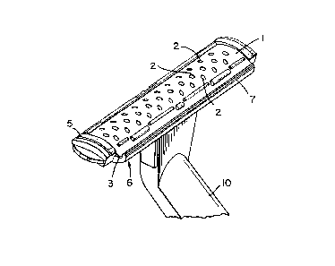
A safety razor in which the blade (1) has a plurality of sharp-edge apertures (2) for shaving and also a sharpened rectilinear
edge (3) for trimming. Provision is made for effecting displacement of the blade relative to the razor handle (10) so that the
trimming edge which is normally in an inoperative position can be moved into an operative position. The blade is held in an
arched position so that the aforesaid movement is of a rocking nature.

Revendications

Note : Les revendications sont présentées dans la langue officielle dans laquelle elles ont été soumises.


THE EMBODIMENTS OF THE INVENTION IN WHICH AN EXCLUSIVE PROPERTY
OR PRIVILEGE IS CLAIMED ARE DEFINED AS FOLLOWS:


1. A safety razor comprising a perforated blade (1)
having a plurality of sharp edged apertures (2) distributed over
its surface, said blade (1) being mounted in a foil carrier (5),
characterized in that the razor further comprises sharpened,
straight continuous trimming edge means (3, 31A); and,
wherein said edge means is formed on a perimeter of
said blade (1).


2. A safety razor comprising a perforated blade (1)
having a plurality of sharp edged apertures (2) and mounted in
a foil carrier (5), characterized in that the razor further
comprises sharpened, straight trimming edge means (3, 31A); and
wherein said edge means is formed on a perimeter of said blade
(1) said razor also comprising:
a support (6) on which said foil carrier (5) is
mounted; and
said foil carrier (5) being operably displaceable with
respect to said support (6);
whereby, said edge means (3, 31A) is normally
inaccessible for use and is selectively brought into orientation
by displacement of the foil carrier (5) relative to said
support (6).


3. A safety razor according to claim 2, characterized
in that said support includes a guard member (7) which normally
obscures the edge means (3), and that the carrier (5) is
disposable, relative to the support (6), to expose the edge
means (3).


4. A safety razor according to claim 3, characterized
in that the carrier (5) is connected to the support (6) in a
bi-stable manner to occupy either of two operative positions,
means being provided for resiliently detaining the carrier (5)
in each position relative to the support (6).


5. A safety razor according to claim 3, characterized
in that the blade (1) is held in an arched condition in the
carrier (5) and that the support (6) is mounted on a handle (10)
for rocking movement about a horizontal axis (C) parallel with
the axis of curvature of the blade (1) and that indexing means
(14) are provided for selectively retaining the support (6) at
an extreme position in its range of rocking movement.


6. A safety razor according to claim 2, characterized
in that said foil carrier (5) is mounted on a handle (10) for
movement between a position of normal use in which the edge means
is substantially inaccessible for use, and an extreme position
in which the edge means is presented in a position of use.


7. A safety razor according to claim 6, characterized
in that the foil carrier (5) supports the blade member (1) in an
arched condition and is mounted on the handle for rocking
movement about an axis parallel with the axis of curvature of the
blade (1), the carrier being displaceable into said extreme
position in which it is held against rocking movement and in
which the edge means (31A) is presented for use.


Description

Note : Les descriptions sont présentées dans la langue officielle dans laquelle elles ont été soumises.

CA 0203789~ 1998-03-23


Safety Razors
This invention relates to safety razors, more particularly
in which a blade member is in the form of a foil having a
plurality of sharp edged apertures distributed over its surface
to constitute a plurality of discrete cutting edges. Such blade
members are referred to in the following description as
"perforated blades".
In accordance with the invention, there is provided a
safety razor comprising a perforated blade mounted in a foil
holder and having a sharpened, rectilinear trimming edge means.
Preferably, the said edge means is normally inaccessible
for use but can be brought into operation by effecting
displacement of at least a part of the foil holder relative to
the razor handle.
The razor can accordingly operate normally as a perforated
blade razor, typically being employed with a reciprocating,
"scrubbing" action, but the sharpened edge means can be brought
into use as required for trimming operations, such as the
trimming of sideburns or moustaches.
Some forms of razor in accordance with the invention are
described in detail below, by way of example, with reference to
the accompanying drawings, in which:-
Figs. 1 and 2 are perspective views of a razor with its
parts adjusted into a shaving mode and a trimming mode,
respectively;
Figs. 3, 4 and 5 are sectional views showing the razor
parts in a normal shaving mode, a fixed position and the
trimming mode, respectively;
Fig. 4A is a scrap detail view taken in the direction of
arrow 'A' in Fig. 4;
Fig. 6 is a perspective view of the head of a second form
of razor;
Figs. 7 and 8 are sectional views showing parts of the
second razor in its normal and trimming positions, respectively;
Figs. 9 and 11 show a third form of a razor in its
different operative positions; and
Figs. 10 and 12 are scrap views illustrating details of the
sg/~,~

CA 0203789~ 1998-03-23


razor of Figs. 9 and 11.
The razor shown in the drawings comprises a perforated
blade 1 in the form of a foil having sharp-edged apertures 2
distributed over its surface and having one longitu~; n~l edge
sharpened to form a trimming edge 3.
The blade is attached to a foil carrier 5 mounted in turn
on a support 6 including a guard member 7 and depending lugs 8
by which the support 6 is mounted on cams 9 fast with the razor
handle 10.
The support 6 is mounted on the handle in a manner which
permits free, rocking movement of the support, relative to the
handle, about an axis parallel with the trimming edge 3. This
is conveniently provided by means of a pair of stationary,
arcuate cams 9 fast with the handle, which engage in arcuate
grooves in the lugs 8 of the support. The centre of curvature
of the cams and grooves is disposed close to the surface of the
foil, for example at the axis 'C' indicated in the drawings.
The carrier has a range of free, rocking movement during
normal shaving to permit additional conformance of the foil to
the skin contours. However, to expose the trimmer edge, the
support must first be latched into its fixed position, shown in
Fig. 4, at one end of its range of rocking movement. For this
purpose, a latch projection 14 is formed on one or both lugs 8
for co-operation with an adjacent portion on the cam 9. As best
seen in Fig. 4A, the latch projection 14 takes the form of a
triangular fillet which presents a stop to free rocking movement
of the support in normal use of the razor. However, the user
can apply some manual effort to force the cam to spring past the
projection 14 into the position shown in Fig. 4.
The support 6 includes a platform section 11 fast with the
remainder of the support and onto which the foil carrier is
clipped in a bi-stable manner. In the "normal" and "fixed"
positions shown in Figs. 3 and 4, the platform 11 is fully
engaged in a channel formed in the underside of the foil
carrier. However, due to the resilience of the parts, the
carrier can be displaced angularly relative to the support, to
the position shown in Fig. 5, in which the forward (left-hand)
sgl~u

CA 0203789~ 1998-03-23


edge of platform section 11 has snapped past a detent projection
13 formed on the foil carrier. This exposes the sharpened edge
for trimming, with the foil carrier and support in fixed
position.
To summarise: the razor is normally in the condition
illustrated in Figs. 1 and 3, in which the edge 3 is safely
obscured and the support 6 and foil carrier 5 can rock as one
about the axis C relative to the handle;
by deliberate m~n~l~l displacement applied through the
carrier 5, the carrier and support can be moved into the
position shown in Fig. 4, in which the edge 3 is still concealed
but the support is held stationary on the handle;
further manual effort applied in the same direction causes
the carrier 5 to spring into the position illustrated in Figs. 2
and 5, exposing the edge 3 for use;
reversal of the above procedure will first restore the
carrier 5 to its normal position relative to the support and
guard, and then release the support for rocking movement about
the axis C.
It will be noted that the latch projection 14 is
asymmetrical in its form so as to present less resistance to
movement of the support into the extreme position of Fig. 4 than
in the reverse direction. Also, it is designed to present less
resistance to relative motion than the catch projection 13 in
one direction than in the other, so that a smaller effort is
required to return the carrier to its normal position than to
return the support to its normal position.
Although movement of the parts into the position shown in
Fig. 4 is primarily intended as a prelude to exposing the
trimming edge, the razor is perfectly operable as a "fixed head"
razor in that condition.
The above described razor may be designed as a disposable
razor, in which case the support 6 is permanently associated
with the handle. Alternatively, the support may be releasably
mounted on the handle cams, or the foil carrier (and foil) may
be releasably mounted on the support so that the foil and foil
carrier, with or without the support, can form exchangeable
Sg/ii

CA 0203789~ 1998-03-23


-- 4
blade cartridges.
In the embodiment illustrated in Figures 6, 7 and 8, the
perforated blade 1 has, in addition to the apertures 2 provided
for normal shaving, a row of elongated apertures 31 positioned
adjacent one edge of the foil. The inner edges of these
apertures are sharpened to form a series of aligned, rectilinear
trimming edges 3lA.
In this razor, there is no movable guard to conceal the
trimming edges in normal use of the razor. Instead, they are
simply positioned so as to be held clear of the skin in the
normal range of attitudes of the blade relative to the handle.
The foil holder 5 is again supported on the cam 9 so as to
have a range of rocking movement in normal use of the razor, to
either side of the medial position shown in Fig. 7. When it is
desired to bring the trimming edges into play, the foil holder
is rocked in a clockwise sense, as viewed in Fig. 7, to force
the cam to spring past the latch projection 14, to lock the foil
holder 5 in the position shown in Fig. 8, in which the trimming
edges 31A are positioned "high up" at the leading side of the
blade foil.
The razor shown in Figs. 9 and 10 is generally similar to
that of Figs. 6 to 8 except for the means of latching the foil
holder in the trimming position. In this embodiment, the handle
is fitted with a m~nll~lly actuated sliding latch comprising rod
20 slidably mounted in a slot 21 in the handle and an external
operating button 22. The rod has a pair of rounded ribs 23 at
its lower end and the sides of the slots are formed with upper
and lower pairs of recesses 24, 26 for co-operation with the
ribs.
The latch is shown in Fig. 9 in its lower, retracted
position, where it is held by engagement of.the ribs 23 in the
lower pair of recesses 24, and in which the foil holder 5 is
free to rock for normal shaving. For trimming operation, the
latch is pushed to its upper, extended position. The upper end
of the rod engages the underside of the foil holder 5 and rocks
the holder clockwise to its extreme position, as shown in
Fig. 11. The parts are all held in this position by engagement
sg/~

CA 02037895 1998-03-23


of the ribs 23 in the upper pair of recesses 26, as shown in
Fig. 12.
Upon manual return of the latch to its lower position, the
foil holder is a~ain free to rock.


~/D

Dessin représentatif
Une figure unique qui représente un dessin illustrant l'invention.
États administratifs

Pour une meilleure compréhension de l'état de la demande ou brevet qui figure sur cette page, la rubrique Mise en garde , et les descriptions de Brevet , États administratifs , Taxes périodiques et Historique des paiements devraient être consultées.

États administratifs

Titre Date
Date de délivrance prévu 1998-07-07
(86) Date de dépôt PCT 1990-07-10
(87) Date de publication PCT 1991-01-25
(85) Entrée nationale 1991-03-25
Requête d'examen 1993-11-17
(45) Délivré 1998-07-07
Réputé périmé 2000-07-10

Historique d'abandonnement

Il n'y a pas d'historique d'abandonnement

Historique des paiements

Type de taxes Anniversaire Échéance Montant payé Date payée
Le dépôt d'une demande de brevet 0,00 $ 1991-03-25
Enregistrement de documents 0,00 $ 1991-08-21
Taxe de maintien en état - Demande - nouvelle loi 2 1992-07-10 100,00 $ 1992-06-11
Taxe de maintien en état - Demande - nouvelle loi 3 1993-07-12 100,00 $ 1993-07-02
Taxe de maintien en état - Demande - nouvelle loi 4 1994-07-11 100,00 $ 1994-06-26
Taxe de maintien en état - Demande - nouvelle loi 5 1995-07-10 150,00 $ 1995-06-29
Taxe de maintien en état - Demande - nouvelle loi 6 1996-07-10 150,00 $ 1996-06-27
Taxe de maintien en état - Demande - nouvelle loi 7 1997-07-10 150,00 $ 1997-06-30
Taxe finale 300,00 $ 1998-03-23
Taxe de maintien en état - Demande - nouvelle loi 8 1998-07-10 150,00 $ 1998-06-26
Titulaires au dossier

Les titulaires actuels et antérieures au dossier sont affichés en ordre alphabétique.

Titulaires actuels au dossier
THE GILLETTE COMPANY
Titulaires antérieures au dossier
BROWN, FRANK EDWARD
TAYLOR, JOHN
WILKES, DAVID JOHN
Les propriétaires antérieurs qui ne figurent pas dans la liste des « Propriétaires au dossier » apparaîtront dans d'autres documents au dossier.
Documents

Pour visionner les fichiers sélectionnés, entrer le code reCAPTCHA :


Pour visualiser une image, cliquer sur un lien dans la colonne description du document. Pour télécharger l'image (les images), cliquer l'une ou plusieurs cases à cocher dans la première colonne et ensuite cliquer sur le bouton "Télécharger sélection en format PDF (archive Zip)" ou le bouton "Télécharger sélection (en un fichier PDF fusionné)".

Liste des documents de brevet publiés et non publiés sur la BDBC .

Si vous avez des difficultés à accéder au contenu, veuillez communiquer avec le Centre de services à la clientèle au 1-866-997-1936, ou envoyer un courriel au Centre de service à la clientèle de l'OPIC.


Description du
Document 
Date
(yyyy-mm-dd) 
Nombre de pages   Taille de l'image (Ko) 
Abrégé 1997-06-18 1 10
Description 1998-03-23 5 214
Revendications 1997-06-18 3 75
Page couverture 1993-11-20 1 14
Abrégé 1993-11-20 1 10
Revendications 1993-11-20 2 67
Dessins 1993-11-20 7 159
Description 1993-11-20 5 213
Description 1997-06-18 5 205
Revendications 1998-05-25 3 75
Abrégé 1998-05-25 1 10
Description 1998-05-25 5 214
Page couverture 1998-07-04 1 40
Dessins représentatifs 1998-07-04 1 10
Correspondance 1998-03-23 6 241
Correspondance 1998-03-23 1 35
Correspondance 1997-09-23 1 95
Correspondance de la poursuite 1991-03-25 9 370
Correspondance reliée au PCT 1991-08-28 1 26
Lettre du bureau 1993-12-30 1 29
Correspondance de la poursuite 1993-11-17 1 23
Correspondance de la poursuite 1996-11-18 2 53
Correspondance de la poursuite 1997-05-09 1 37
Demande d'examen 1996-09-23 2 65
Rapport d'examen préliminaire international 1991-03-25 1 42
Demande d'entrée en phase nationale 1991-04-22 4 146
Demande d'entrée en phase nationale 1991-03-25 3 98
Taxes 1996-06-27 1 59
Taxes 1995-06-29 1 60
Taxes 1994-06-28 1 67
Taxes 1993-07-02 2 89
Taxes 1992-06-11 1 19