Note: Descriptions are shown in the official language in which they were submitted.
2 0~ ~9~~
- 1 - 27754-14
The present invention relates to a flow indicator or
flowmeter with an impeller rotatably mounted in an essentially
circular-cylindrical flow chamber of a flow housing which has an
inlet channel and an outlet channel.
Flow indicators or flowmeters of this type are known.
They yield a direct indication of flow in that the impeller, which
rotates with the flow, is visible from the outside, or they serve
as flowmeters, counters and metering devices in that the impeller
is equipped with alternately polarized magnets at the ends of the
impeller blades. The magnets trigger voltage impulses in a fixed
position pick-up coil. These electric impulses can be amplified
and counted in an electronic circuit from which the quantity of
flow (or flow rate) is determined and displayed on a display panel
by means of light-emitting diodes in units of liters or liters per
minute. Such impeller flow indicators or meters have, for ex-
ample with respect to some floating member flow meters, the advan-
tage of almost viscosity-independent indication or measurement
results. The known devices of this type, as illustrated and des-
cribed for example in DE 37 33 862 A1, are however only designed
for a specific range of flow and must be completely replaced and/
or re-calibrated if the measuring range is changed, which takes
time and work. In addition, this is a source of errors and thus
possibly has a negative effect on the accuracy of measurement.
It is the object of the present invention to design a
flow indicator or flowmeter of the type described at the beginning
in such a way that it can be used to achieve a high accuracy of
measurement for at least a wide measuring range without any cali-
bration.
27754-14
2
This object.:is solved according to the invention
essentially in treat in accordance with the characterizing
portion of claim 1 a nozzle plate, having a nozzle hole of a
pre-determined cx-oss-section, can be inserted so as to be
exchangeably, e.c~. can be screwed, into the inlet channel
and/or the outlet: channel, and that the diameter D (in mm) of
the nozzle hole c:an be fixed as a function of the lower limit R1
of the measuring range such that the diameter D increases with
the increase in the value of the ratio V=R1/D, whereby V has a
value of about 0.075 liters of water/mm.min if the diameter D
amounts to about 1.25 rnm and has a value of about 0.3 liters of
water/mm.min if the diameter amounts to about 20 mm. The
nozzle plate can thus be easily replaced with another nozzle
plate with an ap~~ropriate nozzle hole diameter, whereby the
device can be de~~igned for different measuring ranges to
achieve a high accuracy of measurement.
In an advantageous embodiment of the invention a
particularly higr. accux-acy of measurement for additional
measuring ranges is achieved in that the nozzle hole diameter
of the nozzle plates is staggered in fine steps as a function
of the value of the ratio V=R1/D, as indicated in the table
below:
D (mm) V (litres of water/mm.min)
1.2!~ ~ 0.075
1.90 ~ 0.090
2.55 ~ 0.15
7.60 ~ 0.20
12.70 ~ 0.22
15.25 - 0.25
19.05 - 0.30
CA 02037993 2000-OS-09
27754-14
2a
In known flow indicators, which are equipped with
magnets of alternating polarity mounted to the blades of the
impeller, an even number of blades is required. However, this
can lead to unde:~ired _resonances and starting difficulties for
the impeller. Tree resonances result in a significant load on
the bearing of tree impE=ller, which is further increased by the
fact that the magnet-induced inert mass of the impeller is at a
relatively large
CA 02037993 2000-OS-09
203 799
- 3 - 27754-14
radial distance from the axis of rotation. An advantageous
further development of the invention therefore provides that the
impeller has an uneven number of blades.
To further reduce the flow resistance of the new device,
the peripheral distance between the centre point of the inlet
opening of the inlet channel of the flow chamber and the centre
point of the outlet opening of the outlet channel of the flow
chamber is only about 180° or less, preferably between 180° and
160°.
In a further embodiment of the invention the inlet chan-
nel and the outlet channel are preferably fluidically connected to
the housing openings formed in opposing faces of the flow housing.
Starting difficulties of the impeller can be avoided
with certainty if at least the inlet channel ends obliquely to the
radial direction, preferably at an angle of less than between 10°
and 80° to the radial direction, in the cover of the flow chamber.
This ensures that despite the compact construction the flow will
definitely impinge an impeller blade vertically to the blade of
the impeller.
The outlet channel can also lead obliquely to the radial
direction, preferably at an angle of less than between 10° and
80° to the radial direction, away from the cover of the flow
chamber. With this design, the fluid to be measured can be fed
through the flow chamber starting from either side, depending on
the space requirements.
In order to obtain favourable flow conditions, it is
also proposed with respect to the present invention that the open-
2 03 7993
- 4 - 27754-14
ings of the housing for the inlet channel and/or the outlet chan-
nel be in the centre of the opposing faces of the flow housing.
The flow direction, determined by the central longitudi-
nal axis of the nozzle hole, in the inserted, for example screwed
in position of the nozzle plate preferably leads, independent of
the direction of the inlet channel, obliquely to the radial direc-
tion, preferably at an angle of less than between 10° and 80° to
the radial direction, into the (imaginary) cover of the flow cham-
ber so that starting of the impeller is always ensured.
It is also proposed in a further embodiment of the in-
vention to align the central longitudinal axis of the inlet chan-
nel or the nozzle hole with the radial outer end sections of the
passing impeller blades in order to exert a high torque on the
impeller.
The blades of the impeller can be perforated radially
within the radial outer end sections of the blades, whereby the
mass of the impeller and the resistance during rotation within the
filled flow chamber is reduced.
The distance between the radial outer end sections of
the blades of the impeller and the cover of the flow chamber is as
small as possible, at any rate is less than one millimeter, pref-
erably less than 0.5 mm, so that a seal is almost provided between
the blades and the flow chamber. Due to less leakage, the accur-
acy of counting and measuring is increased.
So that the device can be used not only as a flow indi-
cator but also as a flowmeter, the impeller has a number of peri-
pherally spaced magnets, ferrite cores or similar pulse-generating
elements. In comparison to the state of the art wherein the mag-
2 03 7983
- 5 - 27754-14
nets are provided on the radial outer ends of the blades, the
pulse-generating elements are preferably provided in accordance
with the invention in the vicinity of the axis of the impeller.
This significantly reduces the moment of inertia of the impeller.
The bearings thus have less of a load imposed on them. In addi-
tion, the magnets are not provided in the blades or even their
ends, so that despite the uneven number of blades an even number
of magnets with alternating polarity can be provided to interact
with a fixed Hall probe or ferrite cores can be provided to inter-
act with a fixed coil.
The pulse-generating elements are thereby preferably
combined in a sector plate, whereby one pulse-generating element
is arranged in each sector.
The sector plate can be part of the hub of the impeller
or it can be fixed to the hub.
Furthermore, it is advantageous for the pulse-generating
elements be to arranged adjacent a flat side wall of the flow
housing, namely adjacent that side wall behind which the Hall
probe, the coil or a proximity sensor for generating the electric
pulses is provided. Relatively large electric pulses are obtain-
ed in this manner.
The impeller can be mounted on a fixed shaft, but this
requires adequate lubrication. It is of greater advantage if, in
accordance with the invention, the impeller is fixedly accommodat-
ed on a shaft which is rotatably mounted in the two opposing flat
side walls of the flow housing.
According to a further feature of the invention, the
bearing for the shaft is formed by two bearing elements, one of
2 0~ 799
- 6 - 27754-14
which is axially mounted in a fixed position in one side wall and
,s
the other of which~axially adjustable, preferably from the out-
side, in the other side wall. In this way the impeller can be
assembled quickly and safely and long-term functionability is
assured.
Simple assembly is also facilitated if at least one of
the flat side walls of the flow housing is formed at least par-
tially by a removable, fastened housing cover, as is already
known.
At least one of the flat side walls, which are parallel
to the impeller and preferably receive the bearing elements for
the impeller, or at least one of the housing covers, which have
the same position and function, is made of a transparent material
so that rotation of the impeller due to fluid flow is visible from
the outside and so that a flow indication is given without an
electronic circuit. If both side walls or housing covers are
transparent, it can be optically determined from both sides
whether or not there is a flow in the line in which the flow
housing is connected.
The flow housing can be reliably sealed and easily as-
sembled if the housing covers project with a projection into a
recess of the side walls and are radially sealed there by means of
a packing ring.
The flow housing according to the present invention can
have connecting sleeves for the inlet channel or the outlet chan-
nel which permit a pipe connection either via a thread or a
flange. To permit a simple installation of a pipe connection via
a thread, the connecting sleeves, which are equipped with internal
2 03 7993
-,-
threads for example at their outer ends, are inserted into a
threadless hole of the inlet channel or the outlet channel to form
a seal with a sleeve section by means of a packing ring and the
sleeve section has a groove with a round bottom, opposite which
lies a corresponding groove of the threadless hole formed by a
section of at least one hole of the housing accessible from the
outside. A locking pin, which is designed for example as a
threaded pin, is then inserted into the respective hole of the
housing. In this way, the connecting sleeves cannot be displaced
axially but are rotatable relative to the flow housing, thus pro-
ducing a simple screw connection to the connecting line. The con-
necting sleeves can also be moved relative to the flow housing
during operation of the device without having a negative impact on
the seal of the connecting sleeves. A further structural and
functional advantage is achieved through this.
To obtain as compact a device as possible, the flow
housing in a further embodiment of the invention fits into a re-
cess of the housing of the device designed to receive the elec-
tronic circuit.
The outer configuration of the flow housing is thereby
preferably designed with an essentially cuboid shape and in the
position of the flow housing inserted in the housing of the device
the free outer surfaces of the flow housing preferably align with
the adjacent outer surfaces of the housing of the device. Thus, a
complete compact device with overlapping outer surfaces is creat-
ed. If the device is only to be used as a flow indicator, the
flow housing with the impeller and the connecting sleeves can be
used alone. If, however, the device is also to be used as a flow-
2 03 7993
_8_
meter, it is thus integrated into the housing of the device of the
complete housing. This integration can also be achieved later if,
by a purely visual display of a flow, the quantity of flow is to
be measured by means of magnets, ferrites or similar pulse-gener-
ating elements and an electronic circuit and a display is by means
of light-emitting diodes and/or digital signals.
When the flow housing is integrated into the housing of
the device, it is in particular proposed that the outer surface of
the one flat side wall of the flow housing align with the front
outer surface of the housing of the device. The flat side wall of
the flow housing in question or the housing cover forming it are
perferably made of transparent material so that the device can be
used not only for measuring the quantity o.f flow but also for
merely visual display of flow.
Since the electronic circuit should be not subjected to
temperatures above 100°C, but the fluids to be measured may at
times have higher temperatures, it is also proposed that when in-
tegrating the flow housing into the housing of the device, the
flow housing in the position inserted into the housing of the de-
vice be thermally insulated with respect to the housing of the
device, for example by means of the intermediate layer of thermal
insulating panels.
To be able to modify the device according to the inven-
tion to provide varying ranges of measurement, the front outer
surface of the housing of the device can be equipped with an ex-
changeable graduated plate.
2 03 7993
- 9 - 27754-14
Simple manufacture and assembly of the device is ensured
in that the housing of the device is designed as section of a hol-
low extrusion profile.
To minimize the possibility of exceeding the maximum
temperature in the housing of the device, the outer surfaces of
the housing of the device can be profiled, for example can be pro-
vided with ribs or grooves which extend in the longitudinal direc-
tion of the extrusion so that the individual housings of the de-
vice can be simply cut off during continuous hollow extrusion.
Further aims, features, advantages and applications of
the present invention are set forth in the following description
of the exemplary embodiments on the basis of the attached draw-
ings. All the features that are described or illustrated thereby
form either alone or in any appropriate combination the subject
matter of the present invention, also independent of their combi-
nation in the claims or their dependency.
Figure 1 shows an embodiment of the device according to
the invention in the vertical section A-B of
Figure 3,
Figure 2 shows the device according to Figure 1 in a
horizontal section C-D of Figure 3,
Figure 3 shows a vertical section E-F of the inventive
device according to Figure 2,
Figure 4 shows a section corresponding to Figure 1 of
another embodiment of a device according to the
invention (section A-B of Figure 6),
2 0 3 ~ 9 9 ~ - 10 - 27754-14
Figure 5 shows a horizontal section C-D according to
Figure 6 of the inventive device according to
Figure 4,
Figure 6 shows a vertical section C-D of Figure 5 of the
inventive device according to Figure 4,
Figure 7 shows a device designed as a flowmeter in the
vertical section A-B of Figure 9,
Figure 8 shows a horizontal section E-F of Figure 8 of
the inventive device according to Figure 7,
Figure 9 shows a vertical section E-F of Figure 8 of the
inventive device according to Figure 7,
Figure 10 shows a vertical section A-B corresponding to
Figure 7 for another embodiment of an inventive
device designed as a flowmeter,
Figure 11 shows a horizontal section C-D of Figure 12 of
an inventive device according to Figure 10,
Figure 12 shows a vertical section E-F of Figure 11 of
an inventive device according to Figure 10, and
Figure 13 shows an oblique view of a flow indicator and
flowmeter according to the invention in which
the flow housing is inserted into a recess of
the housing of the device to create a compact
device.
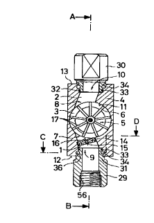
Figures 1 to 3 illustrate a flow indicator according to
the invention, comprising a flow housing 4 with an essentially
circular-cylindrical flow chamber 3 in which an impeller 5 is
rotatably mounted. The flow chamber 3 is equipped with an inlet
channel 1 and an outlet channel 2. The peripheral distance be-
' 2 03 7993
- 11 - 27754-14
tween the centre point of the inlet opening 7 of the inlet channel
1 of the flow chamber 3 and the centre point of the outlet opening
8 of the outlet channel 2 of the flow chamber 3 is less than 180°.
The inlet channel 1 and the outlet channel 2 are fluidically con-
nected to housing openings 9, 10 arranged in opposing faces 12, 13
of the flow housing 4. The housing openings 9, 10 for the inlet
channel 1 and the outlet channel 2 are arranged in the centre of
the opposing faces 12, 13 of the flow housing 4. From the housing
opening 9, the inlet channel 1 leads obliquely to the radial di-
rection by means of the inlet opening 7 into the cover 11 of the
flow chamber 3. The outlet channel 2 leads obliquely to the radi-
al direction from the outlet opening 8 away from the cover 11 of
the flow chamber 3. A nozzle plate 14, which is equipped with an
external thread and a nozzle hole 15 of a pre-determined cross-
section, is screwed into the inlet channel 1 equipped with an
internal thread. The nozzle plate 14 is provided with two extern-
al engaging openings for a lathe tool. The central longitudinal
axis 16 of the nozzle hole 15, like that of the inlet channel 1 is
thereby aligned with the radial outer end sections 17 of the
blades 6 of the impeller 5 travelling past the inlet opening 7.
As indicated in Figure l, the blades 6 of the impeller 5 can
thereby also be perforated. The distance between the radial outer
end sections 17 of the blades 6 of the impeller 5 and the cover 11
of the flow chamber 3 is as small as possible so that fluid leak-
age at the cover 11 is as low as possible.
The impeller 5 is fixed to a shaft 23 which is rotatably
supported in the two opposing flat side walls 22, 24 of the flow
housing 4. The bearing for the shaft 23 is formed by two bearing
2 0 ~ 7 9 9 3 - 12 - 27754-1~
elements 25, 26, one of which is axially mounted in one side wall
22 and the other of which is axially adjustable from the outside
in the other side wall 24. Both flat side walls 22, 24 of the
flow housing 4 are formed by removable housing covers 27, 28 fas-
tened by means of screws 55. The housing covers 27, 28 can be
made of transparent material. The housing covers 27, 28 project
with a projection 51, 52, which receives the bearing elements 25,
26 for the shaft 23 of the impeller 5, in a recess of the side
walls 22, 24. The projections 51, 52 are radially sealed against
the flow housing 4 by means of packing rings 53, 54.
The inlet channel 1 and the outlet channel 2 are provid-
ed with connecting sleeves 29, 30. The connecting sleeves 29, 30
are inserted into a threadless hole of the inlet channel 1 or the
outlet channel 2 such that a seal is formed with the sleeve sec-
tions 31, 32 by means of packing ring 33. The respective sleeve
section 31, 32 has a groove 34 with a round bottom, opposite which
are two corresponding grooves 36 of the threadless hole of the
inlet channel 1 or the outlet channel 2 which are formed by holes
35 of the housing accessible from the outside. A locking pin 37,
which is designed as a threaded pin, is inserted into each hole 35
of the housing. In this way the connecting sleeves 29, 30 are
axially fixed but rotatable with respect to the flow housing 4.
The flow indicator of the invention according to Figures
4 to 6 differs from that illustrated in Figures 1 to 3 for the
most part only in that the connecting sleeves 29', 30' for the
inlet channel 1 and the outlet channel 2 do not have an internal
thread 56 for a pipe connection, rather have a flange 57, 58 for a
2 03 7943
- 13 - 27754-14
flange connection. In addition, the connecting sleeves 29', 30'
are in this case welded to the flow housing 4.
The exemplary embodiment of the device according to
Figures 7 to 9 is similar to that illustrated in Figures 1 to 3.
However, the device illustrated in Figures 7 to 9 is equipped as a
flowmeter which offers not only an optical. flow indication due to
the transparent material of the one housing cover 27 (housing
cover 28 is missing here), but also an electric measurement indi-
cation for the quantity of flow. For this purpose the impeller 5
has a number of peripherally spaced magnets, ferrite cores or sim-
ilar pulse-generating elements 18 which are combined and enclosed
in the immediate vicinity of the axis 19 of the impeller 5 in a
sector plate 20 which is made, for example, of plastic, whereby
one pulse-generating element 18 is arranged in each sector. The
sector plate 20 forms part of the hub 21 of the impeller 5. The
pulse-generating elements 18 are arranged directly adjacent the
flat side wall 22 of the flow housing 4, a Hall generator, a coil
or a proximity circuit element, none of which is illustrated, for
generating an electric voltage or current signal being arranged on
the outside of the flow housing. The flow housing 4 can be fixed
by means of screws 59 in the recess 38 of a housing 39 of the de-
vice, as is shown in Figures 8 and 13.
The embodiment of a device of the invention according to
Figures 10 to 12 corresponds essentially to that illustrated in
Figures 7 to 9. However, the connecting sleeves 29, 30 provided
for a threaded connection are here again replaced by connecting
sleeves 29' and 30' with flanges, these connecting sleeves being
2 03 7993
- 14 - 27754-14
welded to the flow housing 4 similar to the embodiment illustrated
in Figures 4 to 6. The construction is otherwise identical.
Figure 13 shows in oblique view a complete device with a
flow housing 4 which fits in the recess 38 of the housing 39 of
the device and is integrated with it in compact manner. The con-
necting sleeves 29, 30 or 29', 30' are not illustrated. The hous-
ing cover 27 is made of transparent material so that the device
can be used both as a flow indicator as well as a flowmeter with
the aid of the electronic circuit housed in the housing 39 of the
device. The recess 38 of the housing 39 of the device has a
cuboid design corresponding to the outer shape of the flow housing
4 such that the free outer surfaces 40 - 43 of the flow housing 4
align with the adjacent outer surfaces 44 - 47 of the housing 39
of the device. The outer surface 40 of the one flat side wall 22
of the flow housing 4 aligns in particular with the front outer
surface 44 of the housing 39 of the device. The flow housing 4 is
also thermally insulated with respect to the housing 39 of the
device in that thermally insulating panels are placed between the
flow housing 4 and the housing 39 of the device. The front outer
surface 44 of the housing 39 of the device is equipped with an ex-
changeable graduated plate 50 which indicates in analog or digi-
tally the quantity of flow, for example by means of light-emitting
diodes. In this case, additional functions, such as reaching or
exceeding a pre-determined limiting value, the operating state
(on/off) of the device, the signal range (in mA), can be indicated
and actuating members for adjusting the range of measurement and
the like can be provided.
2 t~3 7993
- 15 - 27754-14
The housing 39 of the device is designed as a section of
a hollow extrusion profile and its outer surfaces 40 - 49 are pro-
filed, for example with ribs or grooves extending in the longitu-
dinal direction of the hollow extrusion.