Note: Descriptions are shown in the official language in which they were submitted.
2~3~4
Ni-H2 BATTERY HAVING IMPROVED THERMAL PROPERTIES
BACKGROUND OF THE INVENTION
The present invention relates to a common pressure vessel
type Ni-H2 storage battery, such as may be used particularly in
powering satellites, in which the thermal transfer properties
between the individual battery cells of the cell stack and the
walls of the pressure vessel of the battery are improved.
The earliest Ni-H2 batteries for satellite applications
employed individual pressure vessels for each cell in the
battery. ~owever, to gain improvements in specific energy and
energy density and to reduce the total weight and volume of the
battery, the recent trend has been to incorporate multiple cells
in a stack arrangement within a single pressure vessel. This
type of Ni-H2 battery is termed in the art a common pressure
vessel type battery. Examples of common pressure vessel type
Ni-H2 batteries are described in the following publications: M.
Earl et al., "Design and Development of an Aerospace CPV Ni/H2
Battery", 24th Intersociety Energy Conversion Engineering
Conference, Washington, DC, August 1989, Proc., Vol. 3, pp. 1395-
1400; J. Dunlop et al., "Making Space Nickel/Hydrogen Battexies
Light and Less Expensive", AIAA/DARPA Meeting on Lightweight
Satellite Systems, Monterey, California, August 1987, NTIS No.
N88-13530; G. Holleck, "Common Pressure Vessel Nickel-Hydrogen
Battery Design", 15~h Intersociety Energy Conversion Engineering
Conference, Seattle, Washington, August 1980, ~Qç~, Vol. 3, pp.
1908-1911; and E. .Adler et al., "Design Con~iderations Related
to Nickel Hydrogen Common Pres~ure Vessel Battery Modules", 21st
Inter80ciety Energy Conversion Engineering Conference, San Diego,
California, August 1986, Proc., Vol. 3, pp. 1554-1559.
In Ni-H2 ~atteries, considerable waste heat is generated
during both charge and discharge cycles. In the conventional
common pressure vessel type Ni-H2 battery, the individual cells
were generally disposed inside of an insulating carrier. The
thermal path between the heat generating portions of the cells
and the wall of the pressure vessel was lengthwise through the
battery cell stack components and then through the hydrogen gas
of the battery to the adjacent wall of the pressure vessel. As
a result, the thermal resistance between the individual cells and
~38~
the pressure vessel was high, resulting in undesirably large
temperature increases within the battery.
SUMMARY OF THE INVENTION
It is therefore an object of the invention to provide a
common pressure vessel type Ni-H2 battery in which the thermal
resistance between the individual cells and the pressure vessel
of the battery is greatly reduced, thereby effecting rapid heat
transfer between the cells and the pressure vessel and thus
allowing the specific capacity of the battery to be increased.
In accordance with the above and other objects, the
invention provides a battery comprising a pressure vessel, at
least one thermally conductive rack disposed within the pressure
vessel and having an outer wall conforming to and in thermal
contact with an inner surface of a wall of the pressure vessel
and a plurality of fin~ dividing the rack into a plurality of
compartments, and a plurality of battery cells, one or more of
the battery cells being disposed in each of the compartments in
thermal contact with adjacent ones of the fins. A first spring,
which may be a plurality of flexure springs extending between
ones of the racks, provides a radial force on the racks forcing
the outer walls of the racks into contact with respective
portions of the wall of the pressure vessel. A stopper may be
formed inside of the pressure vessel and a second spring, which
may be a wave spring, is provided for forcing the racks into
contact with the stopper with the stopper in the longitudinal
direction o~ the pre~sure ve~el.
B~IEF DESCRIPTION OF THE DRAWINGS
Fig. 1 iB partially cut-away cross-section view of a common
pressure vessel type Ni-H2 battery constructed in accordance with
a preferred embodiment of the present invention;
Fig. 2 is a cross-sectional end view of the battery of Fig.
1 taken along a line II-II in Fig. l;
Fig. 3 iB a view taken along a line III-III in Fig. 1
showing the configuration of an interior wall of a cell rack of
the battery;
2~3~
Fig. 4 is an enlarged cross-sectional view showing the
details of the joining of a weld ring shown in Fig. 1 to the
walls of the pressure vessel;
Fig. 5 is an enlarged cross-sectional view showing the
relationship between the vessel wall, cell rack and individual
cells of the batter~ of Fig. 1; and
Fig. 6 is a cross-sectional view taken along a line VI-VI
in Fig. 1 illustrating the mode of interconnection between the
cells of the battery.
DESCRIPTION OF THE PREFER~ED EMBODIMENTS
Preferred embodiments of the invention will now be described
with reference to the attached drawings.
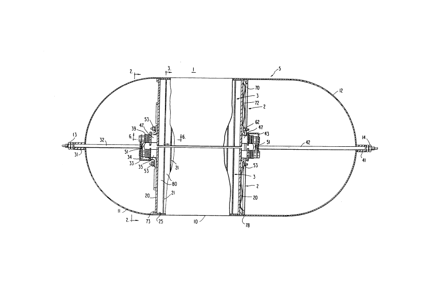
Referring first to Fig. 1, a pressure vessel 5 of a
preferred embodiment of an Ni-Hz battery 1 of the invention is
composed of a central cylindrical portion 10 capped at respective
ends by semi-spherical end portions 11 and 12. Two identical
cell stacks 2 are mounted adjacent one another within the
pressure vessel 5.
Each of the cell stacks 2 includes a cell rack 3 which has
a generally semi-cylindrical outer configuration and is divided
into a plurality of compartments, in each of which is received
one or more battery cells 80. Each of the cell stacks 2 has an
outer wall 25 having the shape of a cylinder sliced lengthwise
along a plane slightly offset from the longitudinal axis of the
cylinder 80 t:hat a small gap iB provided between the two cell
stacka 2. The outer wall 25 con~orms to and is in contact
throughout its surface with th~ inner surface of the adjacent
wall o~ the cylindrical portion 10 of the pressure vessel 5. The
two ends of the outer wall 25 are closed by generally semi-
circular end plates 20. The interior of the rack is divided by
walls or fins 21 into the cell-receiving compartments in which
are disposed the individual battery cells 80.
As shown best in Figs. 3 and 6, each fin 21 has a pair of
cut-outs 76 through which pass cell electrode interconnecting
rods 36 and 46, as will be explained in more detail below. Also,
a grid of holes 68 is formed in each end fin to permit the
circulation of hydrogen gas to the end battery cells 80. All
~3g3~
components of the racks 3 are formed of a metal such as aluminum
or another material having a good thermal conductivity.
With reference to Fig. 5, each battery cell ~0 contains a
repeating pattern of a gas diffusion screen 82, negative
electrode 83, separator 84, and positive electrode 85. The
arrangement of and selection of the materials for these
components is conventional and will within the skill of those
similar with this art. ~ach cell 80 is encased in a plastic bag
81 which electrically insulates the above-mentioned components
from the fins 21. The outer sides of the bag 81, however, are
in intimate thermal contact with the fins 21 on both sides of the
cell 80 as to provide good thermal conduction between the cell
80, over its entire surface, and the fins 21.
As shown best in Fig. 6, each cell 80 has positive electrode
terminals 86 and negative electrode terminals ~7 to which are
respectively connected the positive and negative electrodes 85
and 83 of the cell 80. Insulated interconnecting rods 36 and 46
pass through center holes in the terminals 86 and 87,
respectively. Contact with the fins 21 is avoided by the
provision of the cut-outs 76.
Referring to Figs. 1, 2 and 6, the ends of the rods 36 and
46 pass through respective cut-outs formed in the end walls 20,
terminal link spacers 35 and 47, and washer stacks 39, and are
fixed in place by nuts 34. The terminal link spacers on the rods
36 and 46 from one end of one cell stack 2 are interconnected
through a bus member 33 to a terminal rod 32, and thence through
an insulating ~leeve 31 fixed to the end member 11 of the
pressure vessel 5 to a positive output terminal 13. Similarly,
the terminal link spacers on the rods 36 and 46 from the other
cell stack 2 are interconnected through a bus member 43 to a
terminal rod 42, and thence through an insulating sleeve 41 fixed
to the end member 12 of the pressure vessel 5 to a negative
output terminal 14.
A segmented stopper 73 is fixed to the inner surface of the
cylindrical portion 10 of the pressure vessel 5 and the junction
with the end portion 11. ~lternately, an annular stopper or
another weld ring can be used in place of the segmented stopper
~333~
73. Rim portions of the end walls 20 of the racks 3 abut against
the stopper 73. As shown in the enlarged view of Fig. 4, an
annular shaped weld ring 70 is fixed between the ~ylindrical
portion 10 and the end portion 12 of the pressure vessel 5 by
welding 78. A wave spring 72, fitted between the weld ring 70
and the opposite end of the racks 3, provides preloading on the
racks 3 in the axial direction thereof. Further, flexure springs
51, attached by bolts 53 and 62, are coupled between the end
walls 20 of the two racks 3 at both ends thereof. The flexure
springs 51 provide a radial preloading force on the racks 3 which
urges their outer walls 25 into contact with the inner surface
of the wall of the cylindrical portion 10 of the pressure vessel
5. Due to these two preloading forces, the structural response
to vibration of the assembly i8 eliminated and the thermal
rQ~istance between the racks and the pres6ure vessel 5 minimized.
With the above-discussed battery structure, heat generated
within each battery cell 80 is rapidly transferred through the
fins 21 to the outer wall 25 of the racks 3, and thence, due to
the tight contact between the wall 25 and the cylindrical portion
10, to the pressure vessel 5. As a result, the thermal
conductivity between the battery cells 80 and the pressure vessel
is greatly improved compared with a conventional common
pressure vessel type Ni-Hz battery.
Although preferred embodiments of the invention have been
described, it is believed that numerous modification~ and
alterations thereto would be apparent to one of ordinary skill
in the art without departing from the spirit and scope of the
invention. For example, although the above preferred embodiment
of the invention has been described with reference to a pressure
vessel which is circular in cros~ Yection, the invention can
equally be applied to batteries having a pressure vessel with a
rectangular or other desired cross section. Also, different
types of Rprings than those described above can be used so long
as they provide the requisite preloading forces. Moreover,
although it is preferred to practice the invention with a common
pressure vessel type battery, the invention can be applied to
batteries having individual pressure vessels. Yet further, the
2~83~
invention can be applied to batteries other than those of the
Ni-H2 type.