Note: Descriptions are shown in the official language in which they were submitted.
203~5~
`64881-379
2-75607
OPTICAL FIBER BUILT-IN TYPE COMPOSITE
INSULATOR AND METHOD OF PRODUCING THE SAME
The present invention relates to optical fiber ,
built-in type composite insulators which are mainly used
in detection systems for finding out fault points at
electric power transmission lines and transformer
05 substations, etc., and a method of producing the same. ;
Heretofore, in order to automatically find out
fault points in electric power systems, optical fiber `
built-in type composite insulators have been used which
are capable of transmitting signals from optical sensors
10 at power supply side to detectors at grounded side and ~
maintaining electrical insulative property. ; ; ;
Various types of optical fiber built-in type
composite insulator are known. Among them, a technique
is known wherein a penetration hole is bored in the axis
~- 15 of a ceramic insulator body, one or two optical fibers are
inserted in the penetration hole, and a portion or the
whole of the penetration hole is filled with an organic ~`~
insulative material, such as silicone rubber or epoxy ~;
resin, etc., to seal the optical fiber in the penetra~
tion hole and prevent decrease of creepage distance of
the insulator, and a technique is known wherein the
whole of a ceramic insulator having a penetration hole
and an optical fiber therein are heated and a molten ~
- 2- ~ ~` -
. , .. .. . . . ~ . . . . . , . , .. . . , . ~
2~3~ 7
64881-379
glass is poured in the whole or a portion of the
penetration hole to seal the optical fiber in the
penetration hole.
However, in the abovementioned sealing with
0~ an organic material, the organic sealing material and
the ceramic insulator body have a so large difference of
thermal expansion coefficients from each other, that
problems occur in that deterioration of the organic
sealing material is accelerated and the optical fiber is
occasionally broken by a thermal stress generated by
temperature change in use environment. Moreover, the
organic sealing material has a pxoblem in th~t it is
liable to incur a tracking, etc., during a long use, so
that it has a poor reliability when used for a long
time.
,;; i
Also, in the abovementioned sealing with the
inorganic material or glass, the whole of the long
,......................................................................... . ,.:
~- ceramic insulator has to be heated, so that problems
occur in that a large apparatus is required to increase -
the investment cost and a large electric power is
-~ consumed to increase the running cost. Moreover, when
heating the whole of the insulator and the optical fiber
for melting the glass, problems occur in that the
` coating of the optical fiber is scorched, so that the
`~ 25 optical fiber is liable to break down and the structure
of extending the optical fiber from the ends of the
insulator can hardly be obtained. For obviating the
- ''.:' ' ~'
-3 - -;
203~07
.-................................................................ ;
problems, surfaces of the optical fiber exposed at the
end surfaces of the insulator after sealed by the glass ~`
have to be optically polished and adhered by means of
Ferrule, etc., so that another problems of complicated
and expensive production steps arise.
In order to solve the above problems, the
applicant proposed in their Japanese Patent Application
~ Laid-open No. 1-246,724 tU.S. Patent 4,921,322) two
; sealing methods, as shown in the attached Figs. 4 and 5.
In the sealing method as shown in Fig. 4,
an insulator 31 and an optical fiber 3 are fixed by jigs
26A, 26B for fixing the insulator 31 and jigs 24A, 24B
for fixing the optical fiber 3. These jigs are
constructed in such a fashion that their vertical and --~
horizontal spacings can be adjusted depending on the
positions of the insulator 31 and the optical fiber 3.
For the insulator 31 which has finished preliminàry ~
heating thereof are arranged an induction heating ;`
furnace 21 for melting a glass, a hot air blower pipe
22, and a cooling pipe 23. Next, an upper end of the
insulator 31 is heated by hot blow of a temperature of,
for example, 550C+20C, from the hot air blower 22 for
5 min., and then filled with a sealing glass of `
a desired composition melted at, e.g., 500C in the
-~ 26 induction heating furnace 21 to a sealing portion in the
penetration hole. After filling a desired amount of the
sealing glass to finish the sealing operation at the end
2033~07
of the insulator 1, the insulator 1 is turned over and
the same glass-filling operation as described above is
performed on the lower end portion of the insulator 1 to
complete the sealing process. The cooling pipe 23 is
used for preventing heating of the jigs 24A, 24B which
fix the optical fiber 3.
~ owever, even the method of Fig. 4 has the
following drawbacks. Namely, when the inorganic glass
is filled in the sealing portion after melted by
heating, the neighboring portion of the ceramic
insulator 1 around the inorganic glass can be heated
below the temperature of the inorganic glass and
insufficiently expanded, though the glass is pre-
liminarily heated by the hot blow. As a result, when
1~ the inorganic glass is cooled and solidified, a tensile
stress is exerted on the inorganic glass and the
neighboring portion of the ceramic insulator 1, so that
a crack is liable to form in the sealing inorganic
glass. Moreover, the heated and melted inorganic glass ~ -~
~;20 is difficult to pertain a constant state. Furthermore, -
;~when filling the heated and melted inorganic glass in
the sealing portions of the penetration hole, a high
risk of damaging the optical fiber 3, such as scorching
1, ' , ! , ~ '
of the coating portion of the optical fiber 3, occurs.
6 In the sealing method as shown in Fig. 5,
a preliminary sealing member 41 is formed at first.
That is, at a position of the optical fiber 3 corre~
'. .,.,:
~ - 5-
~'-'',', ' ''
2~3~7
. . .
sponding to the end portion of the penetration hole 2 :
an electrically conductive ceramic or metallic tube 37
having an outer diameter capable of being inserted in
the penetration hole 2 is provided, and a spacer 35 and
a sealing glass 34 are provided in the tube 37 to form :
the preliminary sealing member 41 for sealing the
optical fiber 3 therein.
Next, the optical fiber 3 with the preliminary
sealing member 41 therearound is inserted in the
penetration hole 2 of the insulator 1 to locate or
position the preliminary sealing member 41 at the end
portion of the penetration hole 2, as shown in Fig. 5.
At this time, a sealing glass 34 preferably of a paste
state should be intervened between the outer circum-
ferential surface of the tube 37 of the preliminary .:
~: sealing member 41 and the inner circumferential surface
~: of the penetration hole 2. Thereafter, a high frequency .~
~ induction heating device 42 is positioned at a position ~-
corresponding to the end portion of the penetration hole
~ 20 2 and high frequency induction heating is effected.
, ~ ,
The electrically conductive ceramic or metallic tube 37
is induction heated by the heating, so that the sealing ~ ~
glass 34 arranged between the outer circumferential:~ :
: surface of the tube 37 of the preliminary sealing member
2~ 41 and the inner circumferential surfare of the
penetration hole 2 is melted to complete the sealing
operation. Thereafter, a protecting member for ;
- 6- ~.
.
` 203~5~7
protecting the sealed end portion, such as silicone
rubber, etc., is provided on the sealed end portion
around the optical fiber 3.
However, even the method of Fig. 5 has
drawbacks in that the portion of the ceramic insulator 1
around the inorganic glass can be heated below the
temperature of the inorganic glass, so that a thermal
stress is generated between the inorganic glass 34 and
the neighboring portion of the ceramic insulator 1 to
occasionally form a crack in the sealing inorganic glass
34 when the glass 34 is cooled and solidified.
Moreover, the inorganic glass 34 used between the
ceramic insulator 1 and the electrically conductive
ceramic or metallic tube 37 is liable to peel off from
~ 1~ the tube 37 at the bonded interface thereof than from
;~ the insulator 1 at the bonded interface thereof during
~; ~ - ",
-~ a long use, so that it has poor reliability of the
bonding portion. Furthermore, positioning of the tube ;;~-
37 at a desired position in the penetration hole 2 is
a difficult work accompanying a danger of damaging the
optical fiber 3 and the tube 37 can hardly be uniformly -~
heated. Furthermore, the tube 37 has to be formed to ~ ;
a desired shape beforehand, a high frequency induction
heating device has to be used for heating the tube 37, ;
2~ and the inorganic glass 34 has to be applied, calcined
and baked on the tube 27/ so that production steps are
difficult, cumbersome and too many.
,",,,," ~".
- 7- ~
'.. ,',',~.`.'
~(j3~
,. ~
64881-379
An object of the present invention is to -
provide an optical fiber built-in type composite
insulator which can eliminate crack formation in the
inorganic glass sealing portion and the neighboring
portion of the ceramic insulator with decreased num~er
of production steps and simplified production apparatus.
Another object of the present invention is to
provide a production method of such composite insulator. ;
A further object of the present invention is to
obviate the abovementioned problems and drawbacks.
Now, the above objects can be achieved by the
present invention.
The present invention is an optical fiber
built-in type composite insulator, including a ceramic
insulator having a penetration hole arranged in the
central axis portion, at least one optical fiber
inserted in the penetration hole, and sealing portions
made of inorganic glass arranged at both ends of the
penetration hole for sealing the optical fiber therein,
~comprising recessed portions of the ceramic insulator
arranged around the ends of the penetration hole, and
heat generating elements arranged in the recessed
portions for heating and melting the inorganic glass to
~form the sealing portions at both ends of the
-~2~ penetration hole.
Also, the present invention is a method of
producing an optical fiber built-in type composite
.
8 ~;
,: ,.
2038~07
64881-379
insulator including the steps of inserting an optical
fiber in a central axis penetration hole of a ceramic
insulator to receive the optical fiber therein, and -
sealing both ends of the penetration hole receiving
the optical fiber by means of an inorganic glass to form
sealing portions at both ends of the penetration
hole, comprising, providing recessed portions in the
ceramic insulator around the ends of penetration hole,
arranging heat generating elements in the recessed -~
portions, and heating and melting the inorganic glass to
form the sealing portions at both ends of the
penetration hole. ; ;
For a better understanding of the present ~;~
invention, reference is made to the accompanying
drawings, in which:
j~5 ~' ' ',
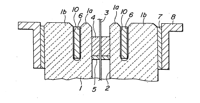
~ Fig. 1 is a schematic enlarged partial cross- ~ -
`~ sectional view of an embodiment of the present composite
insulator showing a state of arranging an inorganic
glass in a recessed portion of a ceramic insulator
around an end of a penetration hole of the c~ramic
insulator; ;~
, ~ ~ , ,.
Fig. 2 is a plan view thereof;
Flg. 3 is a plan view of another embodiment of
the present composite insulator;
~; 2fi Fig. 4 is a schematic front view of a prior
apparatus for sealing an optical fiber in a penetration
hole of a ceramic insulator at the end thereof by means
~ ' , ,;
g
~'~
2~38~07
of an inorganic glass; and
Fig. 5 is a schematic partial cross-sectional
view of another prior apparatus for sealing an optical
fiber in a penetration hole of a ceramic insulator at
o~ the end thereof by means of an inorganic glass.
Numberings in the Drawings
1,31 - ceramic insulator
la -- protrusion
lb -- end portion of the ceramic insulator
2 -- penetration hole for receiving the optical
fiber 3
3 -- optical fiber
4 -- calcined inorganic glass
-- spacer for preventing flow of inorganic glass
16 6 -- ring shaped heat generating element
7 -- cement (adhesive layer)
8 -- flange type metallic fitting
-- ring shaped groove for receiving the heater 6
. .
16 columnar heat generating element
-- round bore for receiving the heat generating
~ element 16 ~;
i~ Referring to Figs. 1 and 2, an enlarged cross-
"~
sectional view and an enlarged plan view of an end
portion of the present composite insulator are shown.
; 26 In Figs. 1 and 2, a ceramic insulator 1 has
a penetration hole 2 for receiving an optical fiber 3,
an inorganic glass 4 is arranged at an end of the
'. ~
- 10~
- ~ 2~3~7 ~:
penetration hole 2, and a spacer 5 is arranged below the
inorganic glass 4 in the penetration hole 2 to prevent
flow down of the inorganic glass 4. The inorganic glass
4 is preferably a calcined body having a hole for
allowing penetration of the optical fiber 3 therethrough
and a diameter corresponding to the inner diameter of
the penetration hole 2. Around the upper end portion of
the penetration hole 2 is provided a ring-shaped or
circular groove 10 which receives and fixes a ring~
shaped heat generating element 6 therein. The upper end
portion lb of the ceramic insulator 1 is held by
a flange type metallic fitting 8 via an adhesive
layer 7.
The ring-shaped groove 10 may be formed at the
15 time of forming the ceramic insulator 1 or it may be ;
:..,, ~ .
formed by working by grinding, etc., after the foxming
or firing of the ceramic insulator 1. The heat generat- ;
ing element 6 has a shape fitted to the shape of the -~
groove 10 and is desirably a heater made of an iron~
2~ chromium-aluminum series alloy or a nickel-chromium
series alloy having a high heat generation power.
When providing a sealing portion in the
penetration hole 2 at the upper end of the ceramic
insulator 1, an electric current is applied to the heat
2* generating element 6 to generate heat therefrom so as to
heat and melt the inorganic glass 4 through the ~;
protrusion la, and thereafter the application of the
'' '~
~Q3~7
electric current to the heat generation element 6 is
turned off to cool and solidify the melted inorganic
glass 4 whereby a sealed portion made of the inorganic
glass 4 is formed.
o~ The same operation as described above is
effected on the lower end of the ceramic insulator l to
provide another sealing portion in the lower end of the
penetration hole 2. The second operation may be
effected se~uentially after the first operation.
According to the production method of this
embodiment, the neighboring portion or the protrusion la
of the ceramic insulator l around the inorganic glass 4
is always maintained at a higher temperature than the
inorganic glass 4 during heating and melting the
1~ inorganic glass 4. Therefore, the protrusion la is -~
expanded not less than the inorganic glass when the
inorganic glass 4 is melted, and the inorganic glass 4;
solidifies and shrinks with a similar shrinkage of the
protrusion la after the sufficient expansion of the
protrusion la. As a result, no tensile stress is
exerted on the inorganic glass 4 and the surrounding
protrusion la, so that a crack is hardly formed.
Therefore, reliability of the sealing property of the
sealing portion can be remarkably improved, and fraction
2~ defective or percentage of rejected products can be
reduced, so that yield-of the products can be noticeably
elevated.
~ ',''
-12- ;
~3~7
Moreover, the ceramic insulator l and the
inorganic glass 4 can be directly bonded without
an intervening metallic tube, etc., so that peeling off,
etc., of the inorganic glass 4 from the ceramic
06 insulator l at the interface thereof scarcely occurs to
improve the reliability of the sealing portion made of
the inorganic glass 4, particularly the reliability of
the sealing portion for a long period of use.
Furthermore, the inorganic glass 4 is arranged
at a desired position in the end portion of the
penetration hole 2 and heated by a heat generating
element 6 arranged with an appropriate spacing from the
inorganic glass 4 to heat and melt the calcined body of
the inorganic glass 4, so that the number of requisite
1~ materials, members and devices necessary for the -
~;~ production or sealing are small and the production steps
are reduced. Therefore, the sealing portions made of
inorganic glass can be quite simply and economically
formed.
The spacing of the heat generating element 6
from the inorganic glass 4 is preferably 5-20 mm.
In order not to decrease the mechanical ~ -~
strength of the ceramic insulator 1, a ratio of the
~:
outer diameter of the circular groove lO to the diameter
2~ of the ceramic insulator 1 is preferably not more than ;~
0.5, and a ratio of the depth of the groove 10 to the
length of the flange type metallic fitting 8 is ~ ~;
-13 - ;
'' ''':~',
';,."'.;'`'''"
2 ~ 3 8 3 ~ 7
,
preferably not more than 0.75.
After finishing the sealing step using the
inorganic glass, the circular groove lO is preferably
removed of the heat generating element 6 and filled with
0~ a waterproof material to prevent invasion of water, etc.
As the waterproof material, silicone rubber is
preferably used, because it can prevent invasion of
water, etc., without suffering from deterioration due to
water, ozone, and ultraviolet ray, etc., and without
forming an internal crack and peeling-off at the bonded
surface due to expansion and shrinkage thereof caused by
temperature change in use environment.
Coefficient of thermal expansion of the
`:
inorganic glass 4 is preferably smaller than that of the
1~ ceramic insulator l, so that a compression stress is
always exerted on the sealed portion made of the
inorganic glass 4 after the sealing. When heating and
melting the inorganic glass 4, preferably the inorganic
~; ~lass 4 arranged in the end of penetration hole 2 is
- .
2~ burdened with a pre~sure from both the upper and/or
lower sides, so that the level of the inorganic glass
after the sealing can always be maintained constant and
the bonding strength of the inorganic glass 4 to the
ceramic insulator l can be improved.
~` 26 ` In order not to scorch the coating of the
optical fiber 3 extruded from the end portion of the
penetration hole 2 to the exterior, when heating and
- 14 -
203~e)07
melting the inorganic glass 4, the extruded portion
should always be cooled during heating.
If an end-protective member made of e.g.,
silicone rubber, epoxy resin, etc., is formed on the
outer periphery of the extruded portion of the optical
fiber 3 after the sealing, the damage of the optical
fiber by means of external force can be prevented.
The spacer 5 for stopping the downward flow of
the molten inorganic glass 4 is preferably made of
Kovar, iron-nickel series alloy, ceramic material or
inorganic fibers having a substantially same coefficient
of thermal expansion as that of the sealing inorganic ~ :
glass 4. -~
In the embodiment shown in Fig. 3, a plural
1~ number (8 in the drawing) of columnar bore 20 are
arranged around the penetration hole 4 instead of the
circular groove 10. Each bore 20 receives a columnar
heat generating element 16, respectively, which
generates heat for heating and melting the calcined body ~-
f the inorganic glass 4.
Hereinafter, the present invention will be
explained in more detail with reference to embodical -
examples with concrete numeral values.
According to the methods as shown in Figs. 1, 4 ``
2~ and 5, an inorganic glass sealing portion is produced, - ;~
respectively.
In the method as shown in Fig. 1, the ceramic
'", .''' ~' ,'' ',
~- ,
-~ 2l~3~7
,- -
insulator 1 has a diameter of 105 mmr and a length of
l,100 mm, and the circular groove 10 has an outer
diameter of 30 mm, a width of 7 mml and a depth of
30 mm. The inorganic glass 4 is made of a lead borate
glass having a low melting point and has a spacing of
5 mm from the heat generating element 6. The inorganic
glass is melted at 500C and left to cool and solidify.
The insulators having the sealing portions of
Figs. l, 4 and 5 are evaluated on operation hours
required for the sealing and reliability of the sealing
property. The results are shown in the following
; Tables l and 2.
Table l OPeration Hours
Sealing method Operation hours . . .
Fig. 4 100
~:
~; Fig. 5 100
Fig. 1 55 -
. ,
-16-
2~3~i07
Table 2 Reliability of Sealinq
Initial Trouble rate after repeated
Sealing troublethermal shock test (~)
methodrate2000 3000 4000 5000
(%)cycle cycle cycle cycle
0 20 30 45
Fig. 5 20 0 0 15 30
Fig. 1 0 0 0 0 0
Note: Each value of trouble rate is expressed by
percentage of occurred leakage in the whole
tested number.
Thermal shock tests shown in the above Table 2 ;,,
are effected by repetition of a cycle of holding the
insulator samples in a hot bath of 80C for 30 min. and
in a cold bath of -20C for 30 min. Each value of the
initial trouble rate ~ is shown by a percentage of ,--
cracked samples detected by a fluorescent damage-
detecting test in the whole number of 20 insulator - ;
samples. Each value of trouble rate after repeated
thermal shock test is shown by a percentage of He-leaked
samples in the whole number of 20 insulator samples
contalning He gas sealed in the central portion of the
penetration hole 2r after repetition of desired cycles
of thermal shock test.
As seen from the above Tables 1 and 2,
according to the present invention, the sealing
operation can considerably be simplified and shortened, ~
~'. "";: '
: .-,
-17- ~
,.~., .
203~07
the initial trouble rate and the trouble rate after
repeated thermal shock can substantially be eliminated,
and the durability and the reliability of the composite
insulator for a long period of use can appreciably be
improved by prevention of crack in the sealing portion.
As described in detail in the foregoing
explanations, according to the present invention,
a recessed portion is arranged in the end portion of the
ceramic insulator around the penetration hole receiving
the optical fiber and the inorganic glass, the heat
generating element is received in the recessed portion,
and the heat generating element is heated to melt the
inorganic glass, so that the neighboring portion of the
ceramic insulator around the inorganic glass can be held
~ 1~ to a higher temperature than the temperature of the
;~ inorganic glass during heating and melting the inorganic
glass. Hence, the neighboring portion of the ceramic
insulator around the inorganic glass is expanded not
less than the inorganic glass prior to the cooling and
- ao solidification of the inorganic glass, and shrinks with
;a substantially same extent simultaneously with the
; shrinkage and solidification of the inorganic glass.
As a result, a tensile stress is not exerted on the
inorganic glass nor on the neighboring portion of the
-~ a6 ceramic insulator, so that a crack is scarcely formed. --~
- Therefore, the reliability of the sealing property of ~;
the sealing portion can exceedingly be improved, and the
-18 -
21~3~5~7
percentage of rejected products can be much reduced.
Moreover, the inorganic glass arranged in the
end portion of the penetration hole receiving the
optical fiber is heated and melted to form an inorganic
0~ glass sealing portion, so that a metallic tube, etc.,
needs not be interposed between the inorganic glass and
the insulator and can be dispensed with. Therefore,
the problems of peeling off of the inorganic glass from ; -
the metallic tube at the bonded interface thereof, etc.,
10 can be prevented to materially improve the reliability ;
of the sealing property of the sealing portion, particu-
larly the sealing property of the sealing portion during
a long period of use. -~
Furthermore, the simple structure of receiving
1~ the heat generating element in the recessed portion and
heating it to melt the inorganic glass affords reduced
materials, members and devices required for the sealing
as well as small number of production steps. Therefore,
the present invention can produce the inorganic glass
20 sealing portion quite quickly, simply and economically. ;
Although the present invention has been ~-
explained with specific examples and numeral values, it
is of course apparent to those skilled in the art that
various changes and modifications thereof are possible
2S without departing from the broad spirit and aspect of
the present invention as defined in the appended claims. -~
- 19- ';