Note: Descriptions are shown in the official language in which they were submitted.
~a38s~8
PiDe Coupling
The invention relates to a pipe coupling having a generally C-shaped
elastomer sealing sleeve.
Pipe couplings of this type, as have been revealed, for example, from
5 German Patent Specification 2,428,101, have revolutionized pipe connection
technology. On the one hand, due to the fact that the sealing lips have larger
dimensions in relation to the nominal diameter of the pipes to be connected
prior to assembly, the possibility results for the couplings to be pushed onto
the pipes in the pre-assembled state and to install them together with said
10 pipes, it being possible for the pipes simply to be placed next to one another
and for the couplings then to be pushed over the joints. On the other hand,
the compression of the lip seal taking place in the circumferential direction due
to the constrictable housing leads to the fact that the radial thickness of the
sleeve increases so that the sleeve is not only pressed against the pipe wall by15 the housing, but tends itself to mold itself to the pipe surface. This results in
a sealing capability which is fully satisfactory even in the case of a rough or
irregular pipe surface and which additionally remains intact for a long time.
The object of the present invention is to design the known pipe coupling
for higher and maximum operating pressures in such a way that the wall
20 thickness of the web does not have to be increased even from the viewpoint
of the dimensional stability of the housing. In other words, this means that thedimensional stability of the housing undergoes an increase which is greater
than that corresponding to the increase in the wall thickness, in which case,
inversely, the constrictability of the housing is to be guaranteed even with an
25 increased wall thickness. In this case, as a result the pressure resistance of
the coupling to extremely high pressures is to be increased by an actual, so-
called "lightweight constructionn. This is understood to be a construction
which is even capable of compensating for the deformability of the housing,
which increases with the diameter of the coupling (in orders of magnitude of
30 2 meters and over) without the wall thickness having to be increased for thispurpose. In this case, the support surfaces contacting the sleeve are intended
to be essentially cylindrical and the steel insert sheet for this purpose is
intended to remain as thin-walled as possible despite higher pressures.
:. _
~1 ~
2038~08
_ --2--
This object is achieved by the features of the present invention in
accordance with which the closure is offset in the circumferential direction in
relation to the housing gap and the housing gap is bridged from the outside by
a slideway projecting below the region of the tensioning screws, which
5 slideway is anchored on the one end section of the housing jacket and has a
curved guiding surface overlapping the other end section of the jacket.
Due to the closure being offset out of the region of the gap, the closure
acting as a tensioning device during the assembly is stabilized or relieved by
the end section of the housing projecting under the screws. Inversely, in
10 contrast to the other housing sections, this housing section is not pulled, but
thrust, the change in shape arising during constriction of the housing not
merely by the measure of the tensioning screws, but also by the measure of
the slideway. By this means, the regular constrictability of the housing remainsintact to its full extent even if the wall thickness is increased.
On the other hand, while it is still constrictable, the housing behaves like
a closed ring insofar as its end sections are no longer interconnected only by
the tensioning screws, but are also supported against one another, such as is
the case, for example, in the tensioning bushing for pipes according to EP
0,186,728 A1, but without the end sections of the housing requiring different
20 constructions in order to be able to be plugged together. In the known
tensioning bushing, the steel insert sheet is to be omitted. In contrast, in thepresent pipe coupling the steel insert sheet remains intact and the housing is
split longitudinally, but it is continuous in the region of the closure so that any
undesired deformations are counteracted not merely by the friction prevailing
25 between the closure parts, but also by the inherent rigidity of the housing:
deformations which tend to produce extremely high pressures in the sections
of the housing extending laterally away from the closure cannot lead to a
constriction in the sleeve cross-section in the region of the closure.
Further advantageous designs of the subject of the invention emerge
30 from the dependent claims.
The invention is explained in greater detail below with reference to the
exemplary embodiment illustrated in the drawing, in which:
Figure 1 shows a perspective illustration of a coupling housing without the
sleeve and
20 38~08
_ --3
Figure 2 shows a section of the upper half of the coupling along the line
ll-ll in Figure 1 and
Figure 3 shows a variant of the coupling housing.
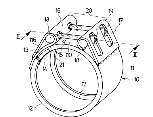
The housing 10 illustrated in Figure 1 and split along the length has a
5 cylindrical jacket 1 1 and end walls 12 bent inwards. The steel insert sheet 14
bridging the housing gap 13 is of analogous construction so that the elastomer
sleeve (not illustrated) is enclosed around the circumference and at the end
faces. It can be seen in Figure 2 that the steel insert sheet 14 is anchored at
15 on the one end section of the housing jacket 11 extending toward the gap
10 13.
Welded onto the housing gap 13 are two tensioning straps 16 and 17,
the free end edges of which are bent round and each surround a tensioning bar
18 and which, in turn, are interconnected by means of two tensioning screws
19. The parts 16 to 19 form a closure denoted together as 20 which is offset
15 in the circumferential direction in relation to the gap 13. The arrangement is
such that the end section 1 10 of the housing extending under the tensioning
screws 19 projects under the tensioning strap 16 which forms a slideway 21
for this end section. For this purpose, the tensioning strap has a stable
anchorage by the fact that its inner limb 116 extends far beyond the housing
20 gap 13 and is connected to the jacket 11 of the housing at two points spaced
apart in the circumferential direction.
By tightening the two tensioning screws 19, the inside diameter of the
overall housing 10 can be reduced as in the case of a pipe clip. In this case,
the end section 110 of the housing projecting underthe slideway 21 is thrust
25 into the space bélow the tensioning strap 16 in the direction toward the other
end section, the coupling housing, although it is still fully constrictable,
constituting a housing of continuous construction in the region of the closure
20. By this means, a greater wall thickness is also compensated in respect of
the regular constrictability of the housing and the stability of the closed
30 coupling housing is increased beyond the measure which would result from a
given wall thickness.
Seen in other terms, it emerges that, due to the closure being offset in
relation to the gap, the housing is divided into two segments of continuously
identical cross-section, of which the one segment is pulled and the other is
2~8~8
-4-
thrust below the slideway without radial offset. In the closed state, the
housing gap and the joint do not lie one above the other between the
tensioning straps, but rather the joint lies above a continuous housing section
which stabilizes the closure in the radial direction and prevents deformations
5 under the effect of compression in the closure region and in the laterally
adJolning regions.
In the variant shown in Figure 3, the housing jacket 11 has on one of its
end sections a support tongue 111 which, in the assembled state, engages in
a corresponding recess 112 in the other end section. In this case, quite
10 considerable pipe tolerances can be tolerated; the thin steel sheet insert is then
adequately supported against high pressures even if the gap remains wide
open, eg. in a pipe with maximum deviation of the diameter from the nominal
bore on the plus side.