Note: Descriptions are shown in the official language in which they were submitted.
2~3~91
-l- 0976CA
TOOLHOLDER ASSEMBLY WITH ANGULAR ADJUSTMENT MECHANISM
FIELD OF THE INVENTION
The present invention relates generally to
machine tools for performing metalcutting operations,
and more particularly, adjustment mechanisms for
machine tools to adjust angular orientation of the
cutting insert.
BACKGROUND OF THE INVENTION
In the process of machining helixes for worm
gears, a cutting tool having two cutting edges is used.
Both of the cutting edges engage the work
simultaneously to form the helix. Because the leading
cutting edge is moving into the helix, sufficient
clearanae must be provided so that the side flank
adjacent the leading edge does not drag or rub on the
helix being formed. Thus, it is usual for the cutting
edge angle of the leading~edge to be more acute than
cutting edge angle of the trailing edge which is moving
away from the helix. The acuteneæs of the leading
cutting edge angle means that the leading cutting edge
will have less support than the trailing cutting edge.
On the other hand, the leading cutting edge
will have a positive cutting rake angle, while the
trailing edge has a negative cutting rake angle. The
positive cutting rake on the leading edge means that
there will be less tool pressure on the leading cutting
-2- 0976CA
edge than on the trailing edge. The greater tool
pressure on the trailing edge will cause it to wear
faster than the leading edge resulting in premature
tool failure. Further, the uneven tool pressure might
cause some deflection of the tool thereby e~fecting the
accuracy of the final workpiece.
Another drawback associated with prior art
tools results from the tool having a fixed geometry.
Since a different tool geometry is preferred for
different heli~es, it is necessary to keep on hand a
relatively large number of different tools. Further,
the machine must be shut down each time a new job is
started so that the tool can be changed.
SUMMARY AND OBJECTS OF THE INVENTION
The present invention is a toolholder
assembly having an adjustment mechanism to enable the
toolholder to be rotated about its own longitudinal
axis. By rotating the toolholder in this manner, the
geometry of the cutting tool with respect to the
workpiece can be varied. The variability o~ the
gaometry of the cutting tool means that a single tool
can be used to cut a variety of different parts.
More importantly, the geometry of the cutting
tool can be optimized for the particular cutting
operation. For instance, in a tool having a fixed
cutting edge angle, side clearance can be obtained
simply by rotating the tool about the longitudinal axis
o~ the toolholder. The ability to rotate the tool
means that the cutting tool can be designed ~ith a
greater cutting edge angle, and thus greater support,
on the leading edge as compared to prior art tools.
Further, by rotating the cutting tool about the
longitudinal axis of the toolholder, the difference
between the side rake angles on the leading edge and
trailing edge can be minimized thereby distributing
tool pressures more evenly.
3~3~
3 0976CA
In the preferred ~mbodiment of the invention,
a rotatable mountiny sleeve is mounted within a bore of
a tool block. The mounting sleeve defines a tool
receiving cavity adapted to receive and hold the
toolholder. Clamping means are provided for holding
the toolholder non-rotatable with respect to the
mounting sleeve. A shaft extends from the back of the
mounting sleeve through the tool block. An adj~stment
mechanism is mounted on the back of the tool blocX and
engages the shaft to rotate the mounting sleeve.
Preferably, the adjustment mechanism includes
an adjustment rod pivotally secured at one end to the
tool block, an adjustment block mounted on the
adjustment rod and movable linearly on the rod, and a
pivot arm fixedly secured at one to the shaft of the
mounting sleeve and pivotally secured at the opposite
end to the adjustment block. To change the angular
orientation of the toolholder, the adjustment block is
moved linearly along the adjustment rod. The linear
movement of the adjustment block is translated by the
pivot arm into rotational movement of the mounting
sleeve.
From the foregoing, it is apparent that the
primary object of the present invention is to provide a
more versatile tool which can be used to machine a
plurality of different parts.
Another object of the present invention is to
provide an adjustable holder for a cutting tool so that
tool geometry can be varied to improve tool
performance.
Another object of the present invention is to
provide an adjustable holder for a cutting tool where
it is possible to make small adjustments in the angular
orientation of the cutting tool.
Other objects and advantages of the present
invention will become apparent and obvious from a study
~,~3~
-4- 0976CA
of the following description and the accompanying
drawings which are merely illustrative of such
invention.
BRIEF DESCRIPTION OF THE DRAWINGS
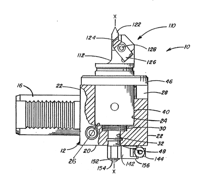
Figure I is an elevation view of the
toolholder assembly of the present invention with a
portion of the tool block removed to illustrate the
tool mounting sleeve.
Figure 2 is a bottom view of the toolholder
assembly of the present invention.
Figure 3 is a top plan view of the toolholder
assembly with the toolholder removed therefrom.
Figure 4 is a section view of the mounting
sleeve taken through line 4-4 of Figure 3.
Figure 5 is a section view taken through line
5-5 of Figure 4.
Figure 6 is a perspective view of the
toolholder adapted for use in connection with the
present invention.
F~igure 7 is a section view of the mounting
sleeve and toolholder taken through line 7-7 of
Figure 3.
DETAILED DESCRIPTION OF THE INVENTION
Referring now to the drawings, and
particularly to Figure l, the tool assembly of the
present invention is shown therein and indicated
generally by the numeral 10. The tool assembly lO
includes a tool block 12, tool mounting sleeve 40,
toolholder 110, and adjustment mechanism. The tool
block 12 includes a block portion having a front face
18, rear face 20, and four side faces 22. A shank 16
extends from one of the side faces 22. A large bore 24
extends from the front face 18 towards the rear face
20. A channel 28 is also formed in the front face 18
2 ~
-5- 0976CA
and extends perpendicularly fxom the large bore 24 to
the side face 22 which is opposite shank 16. A smaller
bore 32 extends from the bottom 26 of the larger bore
24 to the rear face 20 of the tool block 12. A recess
30 is also formed in the bottom 26 of the larger bore
24 for housing a spring washer.
On the front face, are a plurality of bolt
holes (not shown) spaced at 60 intervals~ A series of
degree markings 36 are also etched onto the front face
along one side of the larger bore 24.
A sleeve ~0 is rotatably mounted to the tool
block 12. The sleeve 40 includes a cylindrical side
wall 42, a bottom 44 and an open top de~ining a tool
receiving cavity. An outwardly extending flange 46
projects from the upper end of the sleeve 40. A shaft
extends rearwardly from the bottom 44 of sleeve 40.
The sleeve 40 is adapted to fit within the
larger bore 24 of tool blocX 12 while the shaft 48
extends through the smaller bore 32. As can be seen
clearly in Figure 3, the shaft is long enough to extend
beyond the rear face 20 of the tool block 12 when the
flange 46 seats against the front face 18. The sleeve
40 is secured to the tool block 12 by bolts 50. Bolts
50 pass through slots 5Z formed in the flange 46 of the
sleeve 40 and are threaded into corresponding bolt
holes (not shown) in the front face 18.
A releasable locking mechanism 60 is securely
held inside of sleeve 40. The locking mechanism 60
includes a ball canister 64 which is held by a dowel
pin 62 which engaged in coaxially aligned mounting
holes in the ball canister 64 and sleeve 40. The ball
canister 64 includes two transverse passages 66 and 68
which extend perpendicularly to the longitudinal axis
x-x. A bump-off pin 70 is loosely mounted in a
longitudinal bore 72 and retained there by a second pin
member 74. The ends of the pin 74 are firmly embedded
in the walls of the ball canister 64 and is loosely
2 ~
-6- Og76
engaged in a transverse opening 76 in the bump-off pin
70. The loose fitting between pin 74 and transverse
opening 76 allows for some movement o~ the bump-off pin
70.
Loosely, but non-rotatably engaged within
transverse passage 66 is an actuating member which
includes a head portion 82 and shank portion 84. The
shank portion 84 is formed with threads 86. A torque
screw 88 connects the actuating member 80 to the sleeve
40 while also providing means for reciprocally moving
the actuating member 80.
The torque screw 88 includes an internally
threaded portion 90 which engages threads 86 on the
shank portion 84 of actuating member 80. The torque
screw 88 also has an externally threaded portion 92
which is threaded oppositely to the threads on the
~internal portion 90. The e~ternally threaded portion
92 enga~es a threaded opening 94 in the side wall of
the sleeve 40. On the end of the torque screw 88
accessible from the exterior of the sleeve 40 is a
hexagonal depression 96 adapted to be engaged by an
alIen wrench.
The head portion 82 o~ the actuating member
includes a pair of ball driving ramps 98 on opposite
sides thereof. The ball driving ramps 98 are adapted
to engage locking balls l00 which are loosely held in
the transverse passage 68. The ramps decline inwardly
as they extend away from the shank portion 84 until
they join concave ~pherical depressions 102. The
actuating member 80 also includes an inclined surface
104 adapted to engage a corresponding surface 106 on
the bottom of the bump off pin 70.
It will be readily apparent from the
foregoing description that when the torque screw 88 is
turned in a first direction, the actuating member 80
will be moved to roll locking elements 100 out of
spherical depressions 102 and onto the ball driving
~,~3~
-7- 0976CA
ramps 98. The locking balls 100 are thus driven
outwardly as best shown in Figures 3 and 5. When the
torque screw 88 is rotated in a second direction, the
actuating member 80 is moved in a second direction to
allow the locking balls 100 to roll back into the
spherical depressions 102. At the same time, the
inclined surface 104 engages the corresponding inclined
surface 106 of the bump-off pin 70 to push it upward.
The bump-off pin 70, in turn, pushes upwardly against
the toolholder 110 to break the toolholder free from
the sleeve 40.
Referring now to Figures 6 and 7, the
toolholder is shown therein and indicated generally at
110. Toolholder 110 has a forward portion 112 and a
rearwardly extending, tubular shank 114. A rearwardly
facing abutment surface 116 is formed at the junction
between the tubular shank 114 and forward portion 112.
The forward portion 112 is formed with a tool
receiving pocket 118 adapted to receive a conventional
cutting insert 122. (See Figure 1) The cutting insert
122 includes two converging cutting edges 122a and 122b
which meet to form a rounded cutting tip 123. The top
of the cutting insert 122 is engaged by the clamping
member 126 to secure the insert 126 in its seat 118.
The clamping member 126 is secured to the forward
portion 112 by a clamp screw 128 which threads into a
corresponding hole (not shown) in the top of the
forward portion 112.
When using the present invention to form a
helix, it is important that the tip 123 of the cutting
insert 122 lie on the centerline of the toolholder.
Therefore, when the toolholder is rotated about its own
axis, the radial position of the tip 123 will not be
changed. Instead, only the angular orientation of the
insert 122 is changed.
The shank 114 is an integral part of the
toolholder 110, and is preferably machined from a
-8- 0976CA
single piece of steel. The shank 114 has a frusto-
conical shape and is perforated at two
circumferentially spaced locations by apertures 120.
The tubular shank 114 also includes two diametrically
opposed key slots 130 and 132. ~hen the toolholder 110
is inserted into the sleeve 40, one of the key slots
130 engages key 134 to hold the toolholder 110 non-
rotatable with respect to the sleeve 40. The opposite
key slot 132 slides over the shank of the actuating
member 80. When the toolholder is secured in the
sleeve 40, the tip of the cutting insert 122 should lie
on the longitudinal axis of the tool assembly.
In most prior art tools, the toolholder 10,
and thus the cutting insert 122, has a fixed angular
orientation with respect to the tool block 12. The
fixed angular orientation of the cutting tool has
caused some difficulties. For instance, when cutting
worm gears, the cutting inserts have to be particularly
designed to provide clearance on the leading edge of
the insert so that it can clear the helix being formed.
The amount of clearance needed will depend upon the
pitch of the halix. Thus, it is normal to provide a
separate cutting insert for each helix of a different
pitch.
The present invention overcomes this and
other drawbacks with the prior art by providing means
for rotating the toolholder about longitudinal axis xx
to change the angular orientation of the cutting
insert.
Referring now to Figure 2, the adjustment
mechanism is shown and indicated generally at 140. The
adjustment mechanism includes an adjust~nent arm 142, an
adjustment block 144, and an adjustment rod 146. The
adjustment arm includes a sleeve portion 148 and yoke
portion 150. The sleeve portion 14~ is in the form of
a hex which is adapted to engage with the end of the
shaft 48. The adjustment arm 142 is secured to shaft
-9- 0976CA
148 by msans of a washer 152 and bolt 154 which threads
into the end of shaft ~8. The yoke portion 150 of the
adjustment arm 142 includes spaced apart arms 156 which
extend on opposite sides of the adjustment block 144.
A dowel pin 158 having ends which are firmly embedded
in the yoke arms 156 extends through an opening ~not
shown) in the adjustment block 144. The dowel pin 158
is loosely held in the opening so that the adjustment
arm 142 may rotate about the axis of the dowel pin 158.
The adjustment rod 146 is pivotally secured
at one end to the tool block 12 by dowel pin 162. The
adjustment rod 146 extends through a transverse opening
164 in the adjustment block. Positioning nuts 166 and
168 are threaded onto the adjustment rod 146 and are
disposed on opposite sides of the adjustment block 144.
By tightening positioning nuts 166 and 168 against the
adjustment block 144, the adjustment block 144 can be
held in a fixed position on the rod 146.
It will be readily apparent from the
foregoing description that the adjustment block 144 can
be moved along adjustment rod 146 by repositioning nuts
166 and 168. Further/ when the adjustment block 144 is
moved the adjustment arm 142 will rotate about the
longitudinal axis x-xO Since the adjustment arm 142 is
fixed to shaft 48, the entire sleeve 40 containing
toolholder 110 will rotatè. Therefore, the angular
orientation of the toolholder 110 can be adjusted by
moving adjustment block 144 linearly along adjustment
rod 146.
To adjust the angular orientation of the
toolholder, one of the positioning nuts 166 is threaded
away from the adjustment block 144. The opposite
positioning nut can then be threaded towards the
adjustment block until the adjustment block 144 is
again abutted against the first positioning nut. Both
53~
-10- os76cA
positioning nuts are then tightened against the
adjustment block 144 to fix the block at its new
position.
By providing means to enable the toolholder
to be rotated about its own longitudinal axis, a tool
having a fixed cutting edge angle can be used to cut a
variety different parts. Side clearance for the
leading edge of the tool is obtained simply by rotating
the tool about its longitudinal axis. Furth0r, as a
result of the present invention, cutting inserts can be
designed with greater support for the leading cutting
edge than could previously be obtained used prior art
- designs. Also, by rotating the cutting insert, tool
pressures can be distributed more evenly ~etween the
leading cutting edge and trailing cutting edge. Since
the angular orientation of the tool can be changed, the
present invention eliminates the need to ~eep a
plurality of separata tools for cutting different
parts. In other words, using the present invention, a
single cutting insert can be used to cut a plurality of
di~ferent parts where in the past, separate inserts
were required.
The present invention may be useful for
machining operations other than cutting helixes. For
instance, in full grooving operations, it is useful to
adjust the angular orientation of the cutting insert
without changing the radial position of the cutting
tip. The present invention as previously described,
provides this capability.
Also, the present invention may be useful in
profiling operations to provide the capability to make
very small adjustments in the height of the cutting
insert. To achieve this capability, it is necessary to
offset the cutting insert ~22 with respect to the axis
of the toolholder. When the toolholder is rotated in
-11- 0976CA
very small increments, small changes in the height of
the insert can be achieved only inconsequential changes
in the radial position of the insert.
The present invention may, of course, carried
out in other specific ways than those herein set forth
without parting from the spirit and essential
characteristics of the invention. The present
embodiments are, therefore, to be considered in all
respects as illustrative and not restrictive, and all
changes coming within the meaning and equivalency range
of the appended Claims are intended to be embraced
therein.