Note: Descriptions are shown in the official language in which they were submitted.
2~38G19
A PUSHBUTTON HAVING A LATERALLY DIRECTED INTERNAL NOZZLE FOR A
HIGH PRESSURE FAST RATE SPRAY PUMP
The present invention relates to a pushbutton for a spray
pump or spray head, the pump spraying laterally, and being
intended more particularly to operate at high pressures (of the
order of 100 bars or more) and at a high repetition rate, such
as 50 operations per second (50 Hz) or more, e.g. 100 Hz or
200 Hz. The invention relates more particularly to so-called
"internal" nozzles.
BACKGROUND OF THE INVENTION
One such nozzle is described, inter alia, in French patent
number 2 547 737 and is constituted by associating a channel
which is delimited at a spray or front end by a wall which is
pierced by a central orifice, and a rod whose outside section
is slightly less than the inside section of the channel, the
rod being placed inside the channel, thereby leaving an empty
section of small volume and thus avoiding a dead volume that
would be prejudicial to good spraying. This disposition
eliminates the risk of expulsion towards the front of the
nozzle, which risk is not negligible when pressure is high, and
it facilitates molding the pushbutton, enabling a channel of
great length to be molded in a single piece.
A pushbutton is designed to be mounted on the piston rod
of the pump, commonly called the "valve" rod, which is
constituted by a hollow tube controlling the piston, with the
substance to be sprayed being delivered via said tube. In the
present invention, the spray jet is substantially perpendicular
to the axis of the valve rod.
SUMMARY OF THE INVENTION
According to the present invention, the center of gravitv
of the pushbutton is situated on the axis of the valve rod.
This disposi-tion provides good balance and maintains position
well during repetitive operation at a high rate.
The output channel of the pushbutton into which the valve
rod opens out preferably has a small diameter with a maximum of
about 3 mm and preferably lies in the range 2 mm to 3 mm,
thereby enabling it to withstand high operating pressures while
nevertheless retaining small dimensions.
2038619
BRIEF DESCRIPTION OF THE DRAWING
An embodiment of the invention is described by way of
example with reference to the accompanying drawing, in which:
Figure l is a longitudinal section view on a plane of
symmetry through one example of a pushbutton of the invention
without its nozzle;
Figure 2 is a view of the front face of the pushbutton;
Figure 3 is a view of the rear face of the pushbutton;
Figure 4 is a view of the nozzle; and
Figure 5 is a view on a larger scale showing a detail of
the nozzle.
DETAILED DESCRIPTION
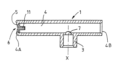
The drawing shows an embodiment of a pushbutton 1 and a
nozzle 2. The pushbutton has a connection endpiece 3 formed to
enable the pushbutton to be fitted in conventional manner onto
the end of the valve rod of a spray pump. The endpiece opens
out into an outlet channel 4 which extends substantially
perpendicular to the axis of the endpiece (which is the same as
the axis of the valve rod). The channel 4 is delimited at its
front end 4A (i.e. the outlet end for the spray jet) by a front
wall 5 which is pierced in its center by a spray hole 6.
The rear end 4B is open. This disposition makes it
possible to place the pushbutton on a pump mounted on a can,
with a spray orifice 6 overhanging the wall of the can. The
section of the channel 4 may be uniform.
However, to facilitate unmolding, the channel may be
slightly conical, flaring towards its open end 4B.
In order to withstand under favorable conditions pressures
that may be very high instantaneously, e.g. 100 bars or more,
the diameter of the channel 4 is small in accordance with a
characteristic of the present invention, and does not exceed
substantially 3 millimeters. Advantageously, it lies in the
range 2 millimeters to 3 millimeters. The disposition with the
internal nozzle makes it possible to mold under good conditions
a pushbutton having an outlet channel which is long enough to
reach or project beyond the outside wall of the can, while
having a diameter suitable for receiving an internal nozzle.
2038~9
According to an important characteristic of the invention,
the center of gravity of the pushbutton including its nozzle
lies on the axis of the valve rod, i.e. on the axis X of the
endpiece 3. This disposition facilitates repetitive rapid
motion of the pushbutton to actuate the pump at a high rate of
not less than 50 Hz, and where applicable 100 Hz or more.
The nozzle 2 shown in Figure 4 is suitable for being
received in the outlet channel 4 in such a manner as to leave a
small-section passage between the orifice 7 through which the
endpiece 3 opens out into the channel 4 and the front end 4A of
said channel, and in such a manner as to close the opening at
the other end 4B.
For closure purposes, the nozzle as shown is fcrmed with
five fastening ribs 8, one of which is shown in section on a
larger scale in Figure 5. Each rib constitutes a peripheral
flange going all the way round a right cross-section of the
nozzle. The section of the flange constitutes a catch 9 having
a latching surface 10 which is directed rearwards. These ribs
thus provide both sealing inside the outlet channel and
retention of the nozzle in the channel. By having a plurality
of ribs, it is possible to withstand very high pressures.
It has been observed experimentally that one rib as shown
is capable of withstanding a pressure of 40 bars. Thus, in
theory, five ribs should withstand a pressure of 200 bars.
In order to define a passage of defined section between
the orifice 7 and the spray hole 6, the front portion 2A of the
nozzle is slightly smaller in diameter than the inside diameter
of the channel 4, and the channel 4 is provided in the vicinity
of its front end with at least three centering projections 11,
thereby defining as rnany passages between the nozzle and the
channel wall between the projections. The projections are of
constant thickness apart from end charnfers for facilitating
insertion of the nozzle to the end of its housing.
The front wall 5 is provided in conventional manner on its
inside face with grooves running from the periphery between the
centering projections 11 to the outlet orifice 6 and reaching
the orifice tangentially so as to impart swirling motion on the
fluid that is expelled.
2o386l9
In addition to being held by the ribs, the nozzle may be
welded to the pushbutton once it has been installed.
A pushbutton of the invention makes it possible to operate
a spray pump at a very high rate and under high pressure,
thereby giving rise to a very fine spray which appears in
practice to be being delivered at a constant rate, thereby
giving an effect identical to that of an aerosol, or which is
even better, while avoiding the drawbacks associated with using
an auxiliary substance that could be considered as being
harmful to the environment.