Note: Descriptions are shown in the official language in which they were submitted.
2038~
F~D D~8PEN~SNG SYSTE~
~i~ld of thQ In~ntion ~ -
The present invention is directed to a system for
dispen~ing a fluid such as gasoline and, more
particularly, to a new and improved fluid dispensing
nozzle incorporating electrical and electromechanical
flow controls and an electrical overflow protection ~i
~echanis~.
Baokqround of the Inv~ntion
Typically, in known gasoline dispensing nozzles, a :.
machanical lever apparatus is utilized to control a main
valv~ in the nozzle to th~reby controllably dispense
fuel, such as gasoline, from a storage tank to the fuel
tank of a ~otor vehicle. The nozzle is caupled to a
hose which is, in turn, coupled to th~ ctorage tank. A
pressurizing device such as a pump is arranged to cause
a pressurized fluid flow, from the storage tank through
the hose and into t~e nozzle. A tubular spout extends
fro~ the nozzle and is arranged and configured for
re~eption into an intake pipe o~ th~ ~otor v~hicle fuel
tank to dispense the fuel in~o th~ fuel ta~k.
.. .. . .
.... . .. , . . ... , . . , . ~ .
. . . - . , . .
~8~
For safety reasons, particularly in self-service
stations, an overflow protection mechanism is provided
to automatically close the main valve of the nozzle when
the fuel tank is filled and the fuel level rises to
above the lower end of the spout inserted into the
intake pipe. In fuel dispensing nozzles in commerclal
use, the automatic valve shut-off mechanism comprises a
mechanical device controlled by the so-called "venturi"
effect.
To use the venturi effect, a small opening is formed in
a wall of the fluid flow channel of the nozzle to
provide an air pasæage from the outside environment,
which is a~ normal atmospheric pressure, to the fluid
flcw channel. Due to the ven~uri effect, the passage of
fluid through the fluid flow channel causes a reduction
in pressure in the air passage resulting in a flow of
air from the outside environment, now at a higher
pressure than the pressure at the channel opening,
through the opening and into a series of tubes and
cavities built into the nozzle. The flow of air
continues as long as fluid is flowing through the
nozzle.
one of the cavitie~ through which.the air flows is a
cylindrical cavity having a flexible di~phragm formed at
its ba~e, with the other cavity walls being rigid and
non-flexible. The outer side of the diaphragm is
exposed to normal atmospheric pressure. A spring
mechanism is employed to exert enough pressure on the
diaphragm from the cavity side to distort and hold the .
diaphragm in a normally concave geometry, so that an
element mechanically coupled to the diaphragm, on the
opposite side Or the spring, will be held in a stable
position at a fraction of an inch (typically in the
order of 0.2 inches to 0.4 inches) from t~e plane of the
undistorted diaphragm.
. . .
As long as the flow of air is undisturbed, the pressure
differential across the diaphragm due to the flowing air
is minimal and is not enough to overcome the effect of
the spring. Thus, in ~ormal operation, the spring will
keep the diaphragm in the dis~orted concave
configura~ion, both while the nozzle is not active (no
fluid flow), and while fluid is flowing through the
nozzle. In this position, a mechanical connection is
established which permits a pivot stem to be held
rigidly in place so that an axis can be established at
the end of the pivot stem which acts as a pivot point
for a user-actuated lever arm. The main flow control
valve of the nozzle is activated by a valve stem which
is positioned so that when the lever arm is rotated by a
user about the pivot point provided by the pivot stem,
the valve stem of the main valve is forced open against
the action of a biasing spring arranged on the opposite
side of the valve. The biasin~ spring exerts a
mechanical force on the valve stem that is sufficient to
close the valve when the lever force is removed.
The Yenturi switching e~fect i5 realized when the air
flow throuqh the air passages is interrupted for any
reason while the ~luid flow continues. To use the
vanturi effect to stop the ~luid flow when ~he fluid
1QVQ1 reaches the nozzle, the air passage begins near
the tip of the nozzle and include~ an air tube which
p~ses d~wn to the tip of the nozzle spout, usually
in~ide the nozzle spout. As soon as tha fluid l~vel in
the fuel tank intake pipe of a motor vehicle reaches the
nozzle spout, the opening of the air tube is covered by
the fluid and the flow of air is inhibited.
The venturi effec~ of th0 continuing fluid flow passing
by the opening in the fluid delivery channel then causes
a rapid decrease in pressure throughout th~ air passage,
which re8ult in a sub~antial pressure differantial
;) b~ '~
across the diaphragm. The pressure differential is
great enough to overcome the force of the diaphraqm
spring and thus forces the diaphragm into a relatively
convex geometry within the cavity, thereby moving the
surface of the center of the diaphragm enough to
disengage the parts, as for example, the pivot stem,
which normally form the mechanical connection permitting
the user-operated valve lever to pivot around the pivot
point.
The parts, which are normally held in place by the
spring action on the diaphraqm, are normally desig~ed ~ -
with bearings such that an orthogonal displacement is
easily accomplished. When these parts are removed fro~ ~ -
the pivot ~tem, the pivot stem is caused to move to a
position allowing the lever arm to freely pivot around
the valve stem such that no force can be applied to the
valve stem via the lever. Since no force can be applied
to the valve stem by the lever, the biasing spring,
which acts against the openlng of the valve, forces th~
valve stem into a valve shut-off position and no fluid
can be dispensed through the nozzle. The biasing spring
is also su~ficiently rigid to act as a pivot point for
the lever after the pivot stem is moved from its pivot
point position.
There are a nu~ber of disadvantages in the use of
venturi switching. For example, before the venturi
e~fect can occur, some ~luid flow mu~t occur to cause
the pressure differential across the diaphragm in the
air passage. This can result in a "splash-back" effect
that occurs when a determined user constantly "~ockeys"
the lever, after the fuel level has reached the nozzle
spout, to res~art fluid flow.
Moreover, an intricate mecha~ical design is rsquired.
The air pa~age has ~o be de~igned such that fuel will
~3~
not flow out of the fluid flow channel and into the air ~-
passage, yet the air passage must accommodate air flow
from outside the nozzle and into the fluid flow channel.
The need for an intricate interface between the fuel
channel and the outside air requires relatively complex
machine work in the fabrication of the nozzle, which
substantially affects th~ cost of manufacture of even a
simple nozzle. Other known nozzles have been proposed to
eliminate a venturi type valve shut down. However, it
is not believed that such other prior art has been used
successfully in a commercial application.
~ummary~o~ the Inventio~
The presen~ invention overcomes the disadvantages of
known nozzles presently in commercial use by providing a
fuel dispensing nozzle having a positive electrical or
electromechanical actuation to open the main valvs of
the nozzle and a mechanical device operating to
automatically shut down the main valve upon any
interruption of electrical power to the main valve as,
e.g. a power interruption controllably actuated pursuant
to the present invention by an electrical overflow
protection device. The pre~ent invention is
particularly useful in solving proble~s in the
distribution of, e.g., gasoline in a retail environment
wher~ the user of the nozzle can be a custsomer not
trained in the handling of fluid dispensing equip~ent. '
Pursuant to one embodiment of the present invention, the
main valve is controllably opened by a mechanical
linkage between a user operated lever and the valve stem
of the Main valve wherein the mechanical linkage
includes an electrically actuated clutch, such as a
magne~ic clutch, arranged to couple the lever side to
the valve ste~ side of the ~echanical linXage. ~he
magnetic clutch is normally energi~ed ~y a source of
.: ,,
, . . .
2 ~ 3 ~ 6 ~
elec~ric power during operation of the nozzle such that
the movement of the lever by a user displaces the valve
stem to open the main valve for fluid flow through the
nozzle. The valve s~em is continuously urged against
the mechanical action of the lever toward a valve shut-
off position by a mechanical device such as a coil
spring. Accordin~ly, an interruption of electric power
to the magnetic clutch will deenergize the clutch
permitting slippage between the lever side and valve
stem side of the mechanical linkage and causing the coil
spring to move the valve stem to the valve shut-off
position.
Pursuant to a feature of the present invention, an
overfIow protection device comprises a fluid actuated
switch device operatin~ to interrupt electric power to
the magnetic clutch upon detection of a fluid rising
within the nozzle spout. In one embodiment of the
inven~ion, the fluid actuated switch comprises a
pressure sensor coupled to a relay that, upon sensing of
fluid pressure caused by a rise of the fluid level to
within the nozzle spout, operates to open a switch in
series with the source of elec~ric power to thereby
interrupt power to the magnetic clutch and cause the
coil spring to shut the main valve.
In accordance with another embodiment of the invention,
the overflow protection device co~prises an optical
s~nsor driven switching mechanism wherein, e.g. a total
internal reflection probe is arranged within the nozzle
spout. Upon a rise of the fluid level to within the
nozzle spout and above the optical sensor, the ~luid
causas a loss of total internal reflection within the
probe which reflection loss is detected and used to
actuate the relay. :
In yet another e~bodiment o~ the invention, thh valve
203~
-7-
stem of the main nozzle valve is mechanically coupled to
an electrical linear or rotary motion device, such as
e.g. a solenoid. The user-operated lever activates a
binary logic control switch device to provide continuous
actuation of the solenoid ~o controllably open and close
the main valve. The binary logic control switch device
can, e.g., comprise an array of proximity switches
arranged in a generally side-by-side relation adjacent
to an actuator mounted upon the user-operated lever. In
this manner, the user can rotate the lever to bring the
a~tuator into operating proximity to either one or both
proximity switches to provide several logical binary
outputs. The binary outputs are utilized to control the
power input to the solenoid to open, close or hold in a ,
preselected position, the valve stem and plug of the
main valve. The valve stem is also urged to a valve
shut-off position by a mechanical device such that the
main valve is automatically closed upon an interruption
of power to the solenoid, as, e.g., by operation of the
overflow protection device according to the invention.
Thus, the present invention provide~ a straightforward,
efficient nozzle that is economical to manufacture.
In ac~ordance with another feature of the invention,
substantially all of the operating par~s of the nozzle
can be mounted within a modular housing that is then
received within a prefabricated plastic handle to
facilitate assembly of the nozzle. Tho electrical
actuation of the main valve provides an easy to use
device for con~rollably opening and olosing the nozzle
valve when di~pensing fuel to a motor vehicle. The
automatic ~echanical valve shut-down upon power
interruption to ~he main valve also provides ef~ective
overflow protection by permitting an s~ficient fluid
level detection ~eans to cause such a power
interruption. The overflow protection i~ achieved
without any dependency on a fluid flow within the
:
~,
nozzle, as required in nozzles that utilize the ven~uri
effect for valve shut-down, thereby avoiding fuel flush
back for safe operation, particularly in self-servioe
stations. In addition, a position sensitive switch can
be mounted in the handle as an additional control such
that the electrical actuation of the main valve can be
achieved only when the nozzle is properly oriented for
dispensing fuel to a motor vehicle.
The ~ozzle according to the present invention can
include a remote source of electric power having an
electrical-to-optical power connector coupled to the
nozzle by optic fibers for safe power transmission by
light. In the alternative, the nozzle can be provided
with a rechargeable battery and a magnetic coupling
device removably magnetically coupled to a corresponding
recharge connector thzt is arranged in the cradle used
to mount the nozzle when t~e nozzle is not in use. In
this manner, the battery can be continuously recharged ~ -
between each use of the nozzle wi~hout the use of any
electrical connectors.
Bri~f ~o~ori~tion of the Drawinq3
.
Fis. 1 is a side, cross-sectional view of a nozzle
accord~ng to the present inve~tion.
Fig. 2~ is a side view of one embodi~ent of a valve and
valve actuator according to the present invention with
the valve illustrated in the closed position.
Fig. 2b is a side view of the valv~ and valve actuator
of Fig. 2a illustra~ing the valve in an open position.
Flg. 3 is a top view Or a magnetic clutch and pulley
sys~e~ of the actuator of Fig~. 2a and 2b. . .
.
.
- 2~3~
Fig. 4 is a block diagram of an electrical system for a
nozzle according to the present invention.
Fig. 4a is a detail of a battery recharge circult of
Fig. 4, according to the present invention. ~ .
.,,~
Fig. 4b illustrates an alternative power source for the
electrical system of Fig. 4.
Fig. 5 is a schematic of a transducer pressure switch of
the elec~rical system of Fig. 4.
Fig. 6 is a schematic of an optical sensor driv~n
switching mechanism according to the present invention.
!
Figs. 7a & 7b illustrate total internal reflection and
fluid blockage of total internal reflection within a
probe tip of the optical sensor driven switching circuit
of Fig. 6.
Fig. 7c i~ a side cross-sectional view of an optical
probe tip according to the present invention mounted
within a nozzle spout. -
~ :';'-
Fig. 8 is a side view of anoth~r embodiment of a valve
and valve actuator according to the present invention.
Figs. 9a-d are schematic views of a control signal input
device of the valve actua~or of Fig, 8 and illus~rate
several binary logical outputs of a proximity switch
arrangement according to the present invention.
Figs. lOa-d are schematic views of a binary control
input signal ~low control circui~ according to the
present invention and illustrate the swi~ch positions
pursuant to s-veral different binary input signals.
' '' '
--10--
Figs. lla & b illustrate a mercury switch device
utilized in the binary input signal flow control circuit
of Figs. lOa-d, in the vertical and horizontal
posit;ons, respectively.
Detail~d Des~ription
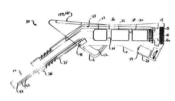
Referring now to the drawings, and initially to Fig. 1,
a fluid dispensing nozzle is generally indicated by the
reference numeral 10. T~e nozzle includes a handle 11
that can be prefabricated from a rigid plastic material
such as, e.g. Lexan brand plastics manufactured by
General Electric Plastics or other suitable materials,
such as cast aluminum. The handle 11 is generally
arranged and configured for convenient handlin~ by a
user and such that a user's index finger is positioned .
over a flow con~rol trigger 12 upon lifting o~ the
handle 11. The ~rigger 12 is rotatably mounted on a
lower surface of the han~le 11 for rotation by the user
to control the flow of a fluid through the nozzle, as
will appear. The handle 11 is provided with an integral :
guard rail 13 that extends around the trigger 12, as
illustrated.
An internal channel 14 is formed within the handle 11
and ~xtends axially through the entire length of the
handl~ 11. As illustrated in Fig. 1, the front portion
of the handle 11 is in an angular relation to the rear
portion thereof to facilitate the insertion of the
nozzle 10 into an intake pipe of a motor vehicle fuel
tank (not illustrated). To that end, a generally --
cylindrical, angled spout 15 is received within and
securely mounted by the internal channel 14 at the
downstream end of the handle 11 to direct fluid 10w to
within the intake pipe. The internal channel 14 is
flared to an expanded internal diameter at the upstream
most end of the mounted spout 15 to receive a modular
2~3~
housing 16 that is inserted through the upstream most
end of the internal c~annel 14 and placed into a fluid
coupling with the upstream most end of the spout 15.
A threaded internal surface 17 of the internal channel
14 threadily engages an outer threaded surface 18 formed
at the upstream end of the modular housing 16 to secure
the modular housing 16 within the internal channel 14 :
and in the fluid communication relation to the spout 15.
A further threaded internal sur~ace 19, at the upstream
most end of ~he internal channel 14, is utilized to
secure the nozzle 10 to a hose (not illustrated) such
that fluid under pressure can flow from a storage tank :~ .
(not illustrated) and into the internal channel 14 of
the handle 11, as described above.
Pursuant to a feature of the invention, the modular
housing 16 is arranged ~o mount, in series, an in-line ,
fluid flow meter 20, e.g., a turbine flow meter, an in-
line flow control main valve 21 and a check valve 22.
The threaded surface 18 of the modular housing 16
surrounds a fluid inlet 16a of the modular housing 16
that is placed in fluid communication with the hose (not
illustrated) ~y virtue of the structural relationship .
between the threaded surfaces 17, 19 of the internal
channel 14 (see Fig. 1). In this manner, fluid flow
from the hose enters the interior of the modul~r housing
16 via the inlet 16a and flows into the in-line turbine :~
flow meter 20.
A pair of fluid channels 23, 24, formed within the
modular housing 16, provides fluid communication between
the in-line flow meter 20 and in-line flow control valve
21 and between the in-line flow control valve 21 and the
oheck val~e 22, respectively. The downstream most end
of the check valve 22 is positioned at the fluid
co~unication interface between the modular hou~ing 16
.. : . - .,., -, ~ , : .
: : ~ : -, . .
. ~ , . : ; . . :
~ ; . : :
2 ~ 3~
and spout 15 so that pressurized fluid flow from the
hose (not illustrated) flows thxough the inlet 16a, in-
line flow meter 20, fluid channel 23, in-line flow
control valve 21, fluid channel 24, check valve 22 and
spout 15 to con~rollably dispense a preæsurized fluid
from a storage tank and into a fuel tank o~ a motor
vehicle, via the nozzle lo.
Substantially all of the moving mechanical par~s of the
nozzle lO are arranged within the modular housing 16,
which is readily inserted into the internal channel 14
of the prefabricated handle ll during assembly of the
nozzle 10 and also readily removable from the handle ll
for repair and/or replacement, if necessary.
A flexible, generally cylindrical vapor recovery seal 25
is affixed to ~he front end of the handle 11 and extends
in a co-axial relation to the spout 15. The seal 25
includes a generally cylindrical end portion 26 having
an open downstream most end that ~ircumscribes the spout
15. The seal 25, including the end portion 26, is
dimension~d so that the open end of the end portion 26
fits over the open end of the intake pipe (not
illustrated) of a motor vehicle when the spout 15 is
insert~d into the intake pipe to dispens~ fluid to the
motor vehicle fu~1 tank. In this manner, fluid vapors
that ~y develop during operation of the nozzle lO are ;
cap~ured by the vapor recovery seal 25. The vapor :
recovery sQal 25 communicates with a vapor recovery
channel 27 formed within the handle ll and arranged to ~ -
extend from the vapor recovery seal 25 to an area within
the internal channel 14 and adjacent th~ thread surface
19. Accordlngly, vapors captured by ths vapor recovery
seal 25 will flow back to the upstream end of the
modular housing 1~ for continued flow to a vapor
recovery system incorporated into thQ hose (not
illustrated).
~3~ ~9~1
A transducer pressure sensor 41 is mounted within the
handle 11 and includes a tube 42 arranged to extend
within the spout lS ~o a position near the downstream
end of the spout lS. A column of air is ordinarily
within the tube 42 such that a rise of fluid level to
within the spout 15 and above the lower most end 43 of
the tu~e 42 causes an increase of the air pressure
within the tube 42. The increased air pressure is
sufficient to actuate the transducer for overflow :~
protection, as will be described in qreater detail
below.
Pursuant to a feature of the invention, the in-line flow
control valve 21 includes an electrical actuation that
is utilized in the control of the opening and closing of
the control valve 21 and an au~omatic mechanical valve
shut-down device that operates to automatically close
the flow control valve 21 upon any interruption of
electrical power to the valve 21.
To that end, in one embodiment of the invention, the
handle 11 includes a battery housing 28 integrally
formed therein to mount a battery 29, which can comprise
a rechargeable battery. The battery 29 provide~ a
source of electrical power to the in-line flow control
valve 21, as will appear.
Referring now to Figs. 2a, b and 3, th~ trigger 12 is
rotatably mounted within the handle 11 by a pivot pin 30 ;
and is connected to on~ end of a trigger C~1Q 31
arranged to extend within the handle 11 to a trigger ~:
pulley 32. Tha other end of the trigger cable 31 is -
connected to and wound around the trigger pulley 32 a ~'
number of turns sufficient to unwind from and rotate the
trigger pulley 32 when a uQer axially displacQ~ ~he : .
trigger cable 31 aw~y ~rom t~e trigger pulley 32 by
rot~ting the trigger 12 about the pivot pin 30. A
-14~
biasing spring 38 is arranged to act be~ween the handle
11 and the trigger 12 so as to urge the trigger 12 in a
clockwise direction relative to the pivot pin 30, to
thereby urge the trigger toward ~he closed valve
position, as illustrated in Fig. 2a. The trigger pulley
32 is rotatably mounted on an axle 33 supported within
the in-line flow control valve 21.
A valve pulley 34 is also rotatably mounted on the axle
33 and is mechanically coupled to the trigger pulley 32
by an electrically actuated magnetic clutch 35. The
magnetic clutch 35 is controllably actuated by a
magnetic clutch coil 36, as will appear, that is mounted
on the axle 33 and received within a recess 37 formed on
the side of the valve pulley 34 opposite from the side
thereof coupled to the trigger pulley 32, as most
clearly illustrated in Fig. 3. A valve cable 39 is
connected at one end to the valve pulley 34. Each of
the trigger pulley 32 and valve pulley 34 can include a
coil spri~g (not specifically illustrated) acting
between the axle 33 and the respective pulley 32, 34 to
urge each pulley in a counter clockwiss rotational
direction.
The in-line flow control valve 21 comprises a valve
housing 40 arranged ~o support a valve cage 44 that
extends within the valve housing 40 in a co-axial
rel~tion to the longitudinal axis of the housing 40. A
valv~ stem 45 is arranqed for axial movement within the
valve cage 44 and includes a valve plug 46 securely
mounted at the downstream most end of the valve stem 45.
The valve cage 44 forms a valve seat 47 that is
con~igured to mate with the valve plug 46 when ~he valve
21 is closed, as illustrated in Fig. 2a.
Fluid flow from the flow channel 23 flows around the
valve cage 44 and into the interior thereof through
- ~ ., .
: , .
~ o ~
-15-
fluid inle~s 48, as indicated by the flow direction
arrows 49, 50. When the valve plug 46 is seated against
the valve seat 47, fluid flow through the flow control
valve 21 is prevented.
A coil spring 51 is mounted within the valve cage 44, in
a co-axial relation to the valve stem 45, and acts
between the valve cage 44 and the valve plug 46 to urge
the valve stem 45 into the closed valve position
illustrated in Fig. 2a. i-
The other end of the valve cable 39 is affixed to the
upstream end of the valve stem 45. Rotation of the
trigger 12 by a user will tension and axially displace
the trigger cable 31 in a direction causing ~he trigger
pulley 32 to rotate in a clockwise rotational direction.
When the magnetic clutch coil 36 is energized, the
magnetic clutch 35 provides a mechanical linkage between
the rotating trigger pulley 32 and the valve pulley 34
thereby rotating the valve pulley 34, also in a
olockwise rotational direction.
This results in the valve cable 39 being wound onto the
valve pulley 34 to thereby apply an axial force to the
valve stem 45, in the upstream direction, against the
coil spring 51 and away from the valve seat 47.
A~co~dingly, the valve plug 46 is controllably lifted
from th~ mating relation with the valve seat 47, as
illustrated in Fig. 2b, to permit fluid flow through the
valve seat 47 and into the flow channel 24. The fluid
inlets 48 are dimensioned so that pressurized luid can
flow to both the upstream and downstream sides of the
valve plug 46 to balance the valve plug 46 for eas~ of
operation.
Referring now to Fig. 4, there is illustrate~, in block
diagram form, th~ elactrical system Or th~ nozzle 10.
:
2 0 ~ 8 r
--16--
The battery 29 is electrically coupled to a trigger
switch 52, which is, in turn, electrically coupled to
the magnetic clutch coil 36. The electric circuit is
completed by an electrical coupling between the magnetic
clutch coil 36 and the transducer pressure switch 41 and
a further electrical coupling be~ween the transducer
pressure switch 41 and the battery 29. The trigger
switch 52 is arranged adjacent to the trigger 12 (not
specifically illustrated) such that, upon rotation of
the trigger 12 by a user, the trigger 12 contacts and
closes the trigger switch 52. The trigger switch 12
remains closed as long as the trigger 12 is displaced
from the valve closed position illustrated in Fig. 2a.
The transducer pressure switch 41 is normally closed.
Thus, upon the closing of the trigger switch 52, the
magnetic clutch coil is energized, and the above-
described cable displacement due to the rotation of the
trigger 12 causes the valve to open.
Referring to Fig. S, the transducer pressure switch 41
includes, e.g. a normally open low-pressure switch 53
manuf~ctured by World Magne~ics. The low pressure
switch 53 is electrically coupled in series with the -'
battery 2g and an electro mechanical relay 54 that is
coupled to a normally closed switch 55. The switch 55
is electrically coupled in series with the ~a~tery 29
and magnetic clutch coil 36 and in parallel to the low
pressure switch 53 and relay 54. As described abovel
the rise of the fluid level to above the end 43 of the
tube 42 causes an air pressure increase within t~e tu~e
42 to close the low pressure switch 53 to thereby
ener~ize the relay 54. The relay 54 will then operate
to m~chanically open th~ switch 55 to interr~lpt
electrical power to the magnetic clutch coil 36.
Upon an interruption of electric power to the magnetic
clutch coil 36, the valve pulley 34 will slip relative
2 ~ f~ ~
to the trigger pulley 32 and the coil spring 51 will
cause the valve stem 45 t~ move toward and ints the
closed valve position illu~trated in Fig. 2a. The
automatic valve shut down provided by the operation of
the transducer pressure sensor 41 and the coil spring 51
does not depend upon a fluid flow within the nozzle and
any manipulation of the trlgger 12 by a user after valve
shut-down will not restart fluid flow.
In accordance with another feature of the invention, the
battery 29 comprises a rechargeable bat~ery and includes
a recharge circuit 56 that is removably coupled to a :-
recharge circuit power supply 57. The recharge circuit
power supply 57 can be mounted in a cradle or other
support (not specifically illustrated) used to hous~ the
nozzle 10 when the nozzle lO is not in use.
A~cordingly, the battery 29 can be continuously
recharged between each use of the nozzle 10. The
recharge circuit 57 is coupled to an AC power supply 58
that can be remote from the recharge circuit 57 and used
to power other similar recharge circuits used throughout
a service station.
. .. .
Referring now to Fig. 4a, there is illustrated a `
recharge circuit 56 according to ~he present invention.
The recharge circuit 56 comprises a transfor~er
secondary coil 200 wrapped around a first magnetic core
201. Two leads 202, 203 of the transfor~er secondary
coil 200 are coupled as inputs to a full wave diode
rectifier 204. Leads 205, 206 provide a DcC. output of
the diode rectifier 204, for coupling to the
rechargeable battery 29, as indicated in Fig. 4a.
The recharge circuit power supply 57 comprises a
transformer primary coil 207 wrapped axound a s2cond :
magnetic core 208 and mounted within a support for the
nozzle lO, a~ described above. Pursuant to a featuro of `.
. ~ . . .
., .......... . -... .. . .. . . ,: - .. : ~ . . : -
-18-
the invention, the second maqnetic core 208 is arranged
within t~e support at a position closely proximate the
position of the first magnetic core 201, when the nozzle
10 is mounted by the support, to compl~te a magnetic ~ -
coupling between the first and second magnetic cores
201, 208. In this manner, current flow in the pr~mary
coil 207 will induce current in the secondary coil 200
to power the rectifier 204 and thereby recharge the
battery 29. Thus, the power coupling between the
recharge circuit power supply 57 and recharge circuit 56
is achieved solely by a magnetic coupling and without
the need for any removabls electrical couplings.
A pair of leads 209, 210 electrically couple the primary
coil 207 to the source of AC power 58. A switch 211 can
be coupled in series with the primary coil 207 for
on/off control of the power supply 57. For example, the
switch 211 can be closed by the nozzle 10 when mounted
in the support, so that current only flows in the coil
207 when needed to supply power to the rectifier ~04.
A further embodiment of the present invention is
illustrated in Fig. 4b. An optical to electrical
converter 2~0, including a rectifier, i5 used to replace
the battery 29 and is coupled between the ~rigger switch
52 and press~re transducer 41. The converter 250 is
coupled by an optical cable 251 to an optical power
output of an electrical to optical power converter 252,
mounted within the suppor~ for the nozzle 10. The
converter 252 is, in turn, electrically coupled to the
source of AC power 58. A switch 253 can be coupled in
series with the converter 252, for on/off control of the
converter 252. :
Pursuant to another embodiment of the present invention,
power interruption to the electrical in-flow control
valve 21 is cau~ed by detection of a rise of fluid level
- - . . . . .
--19-- :
within the spout 15 by an optical sensor driven
switching mechanism. Referring to Fig. 6, there is
illustrated a schematic for an op~ical sensor driven
switch 41' used in place of ~he transducer pressure
switch 4~. Similar to the transducer pressure switch
embodiment, a normally closed switch 55' is electrically
coupled in series with the magnetic clutch coil 36 and
the battery 29. The switch 55' is coupled to a relay
54' that operates ~o open the switch 55' upon optical
detection of a rise in the fluid level to within the
spout 15, as will appear.
As illustrated in Fig. 6, the relay 54' is electrically
coupled in series with the battery 29 and a normally
closed switch 56. As long as the normally closed switch
56 is held in the open position, the relay 54' is not
energized and power is supplied to the magnetic clutch
coil 35. To that end, the normally closed switch 56 is
coupled to a relay 57 that ordinarily holds the switch
56 in the open position. The relay 57 is electrically
coupled in series to the battery 29 and a photo-diode
detector 58 that is in a conducting state when a source
of li~ht is applied to the photo-diode detector 58c
.
A source of light co~prises a photo-emitter diode 59,
electrically coupled in series to the battery 29 and
optically coupled to an optical probe 60 arranged ~o
extend within the spout 15 to a position near the
downstream most end of the spout 15, similar to the air
tube 42.
Referring to Fig. 7a, the optical probe 60 co~prises a
total internal reflection probe having an index of
reraction substantially equal to the index of
refraction of the fluid being dispensed by ~he nozzle
and including a continuous loop of optical fib~r
extending from the photo-emitter diode 5g down ~hrough
' ~ . . ', , .,, ~
~ ~ 3 ~
-20- :
tha spout 15 and back to the photo-diode detsctor 58.
The downstream most end 61 of the optical fiber loop is
arranged and configured to have radii of curvature at
each loop bend 62 suitable to provide internal
reflection within the fiber 60 of the light 63 provided
by the photo-emitter diode 59 for transmission to and
reception by the photo diode detector 58. As described
above, as long as the photo-diode detector 58 receives
light, it will conduct, causing power to be supplied to
the relay 5~ which then operates to hold the switch 56
in an open position.
Referring to Fig. 7b, when the fluid level 64 rises
within the spout 15 and above the bends 62 of the
optical probe 60, a significant portion of the light is
not reflected ~t the fiber surface, but continues into
the fluid, due to the near equal indexes of refraction
of both the optical fiber and the fluid. Accordingly,
the amount of light reaching the photo-diode detector 58
is greatly diminished causing an interruption of power
to the relay 57. This results in the switch 56
switching to its norm~lly closed position to thereby
energize the relay 54', that then operates to
mechanically open the switch 55~ to interrupt power to
the magnetic clutch coil 36.
As illustrated in Fi~. 7c, the optical fiber probe 60
that extends within the spout 15 is covered by an opaque
shield screen 65 to prevent normal fluid flow through . .
the spout 15 from affecting light reflection and
transmi~sion within the probe 60. The downstream most
end of the probe 60, including the loop bends 62, is
received within a housing 66 that is mounted to an
internal wall of the spout 15 and is arranged to
surround ~he downstream most end of the probe 60. The
housing 66 also prevents normal fluid flow through the
spout 15 from af~ecting light reflection at the loop
. ~ . . . . - ~ . . . . ...
. ~ .
:
~ ';3
-21
bends 62. The housing 66 defines an open end 67 that
faces the downstream direction of fluid flow within the
spout 1~ and is positioned adjacent the downstream most
end of the spout 15. Moreover, an air/vapor aperture 68
is formed through the spout 15 to provide fluid
communication between ~he interior of the housing 66 and
the atmosphere.
Accordingly, light transmitted from the photo-emitter
diode 59 through the probe 60 will be reflected at the
loop bends 62 and trans~itted to the photo-diode
detector 58 so long as the level 64 of fluid is below
the bends 62 of the probe 60, irrespective of fluid flow
within the spout 15. When the fluid level 64 rises to
within the spout 15, fluid will enter the housing 66
through the opening 67 and rise with the rise of the
fluid level within the spout 15 to the loop bends 62 to
interrupt internal reflection within the probe 60 and
cause power ihterruption to the in-line flow control
valve 21, as de~cribed above. Any air or vapor within .`
the housing 66 prior to the rise of the fluid level to
within the housing 66 will escape from the int~rior of : .
the housing 66, under pressure caused by the rising
fluid, through the air/vapor aperture 68.
Ref~rring now to Fig. 8, there is illustrated another
e~bodiment of a valve actuator according to the pr~sent
invention. The valve itself is si~ilar in construction
to the valve of the embodiment illustrated in Figs. 2a & ~:
b and like reference numerals are u ~d to designat~ the
valve housinq 40, valve cage 44, valve stem 45, valve : ;
plug 46, valve sea~ 47, fluid flow inlets 48 and spring :.
51. However, in Fig. 8, the valve stem 45 i~ in a
direct mechanical coupling ko an electric drive ~otor
device 70 that controllably operates to mov~ the valve
stem 45 linearly in valve op~ning and valv~ closing
directions. ~h~ mo~or d~vic~ 70 can comprise a rotary ~ -
'
., : . - ~ ~ . ~ , .
~38~
motor having a known rotary-to-linear ~echanical
coupling to the valve stem 45 or a linear electric
motor, such as a solenoid, directly mechanically coupled
to the valve stem 45. In the illus~rated embodiment,
the motor 70 comprises a pull solenoid.
The valve stem 45 is also formed to include a pair of
saw-tooth surfaces 71, 72, which are pitched opposite to
one another, as illustrated in Fig. 8. A lever 73, 74
is rotatably mounted adjacent each surface 71, 72, each
lever 73, 74 including a surface engaging tip 75 tha~ is
controllably moved into engagement with a respective
surface 71, 72 by rotation of the corresponding lever
73, 74. The saw-tooth surface 71 is pitched such that,
when the tip 7S of the lever 73 is in engagement with
the surface 71, the valve stem 45 can be moved in a
valve opening direction, but is prevented fro~ moving in
a valve closing direction by the engagement between the
saw-tooth surface 71 and the tip 75 of the lever 73.
Similarly, the saw-tooth surface 72 is pitched such
that, when the tip 75 of the lever 74 is in engagement
with the surface 72, the valve stem 45 can be moved in a
valve closing direction, but is prevented from moving in
a valve opening direction ~y the engagement between the
saw-tooth surface 72 and the tip 75 ef the lever 74.
Each of the levers 73, 74 is connected to a coil spring
76 that urges the respective levers 73, 74 away from
engage~ent with the corresponding saw-tooth surfaces 71,
72. Moreover, each lever 73, 74 is mechanically coupled
to a push solenoid 77, 78 that operates, when energized,
to push the respective lever 73, 74 against the action
Or the spring 76 and into engagement with the
corresponding saw-tooth surface 71, 72. 0~ course, the
springs 76 operate to disengage the lev~rs 71, 72 from
the saw-tooth surfaces 71, 72 whenever the re~pective
.: .- .: - , , ~ .
, . , , -
~3~
-23-
solenoids 77, 78 are deactivated.
Pursuant to a feature of the invention, each of the
solenoids 77, 78 and the electric drive motor device 70
are coupled to a power supply 79 that opera~es to
selectively energize those devices in aocordance with an
input binary control signal. For example, a two bit
binary signal can represent four different binary input
control signals: 00, 01, 10 and 11. Each of the
control signals causes the power supply 79 to energize
the solenoids 77, 78 and the electric drive motor 70, as
follows:
Control Motor Solenoid Solonoid
Siqnal 70 77 __ _78
00 no motion not activated not activated
01 close valve not activated activated
direction : .
open valve activated not activated
direction
11 no motion activated activated
The various binary control signals are generated by a
control input signal device 80 coupled to the power
supply. In one embodiment of the inven~ion, the control
input sisnal device 80 comprises a pair of si~e-by-side
proximity switches 81, 82 arranged adjacent to the
trigger 12, as illustrated in Figs. sa-d. The proximity
switches 81, 82 can comprise either magnetic or optical
proximity switches. The trigger 12 is formed to include ;-
an actuator arm 83 mounting an actuator 84 operable to `:
activate one or both of the proximity switches 81, 82 by
rotating the trigger 12 to bring the actuator 84 into
activating proximlty to one or both of the proximity
switches 81, 82O
., , - , . .
.,
: . , - . . .
2~38~
As illustrated in Fig. 9a, the trigger is in the closed
valve position (see Fig. 1) and the actuator is spaced
from both of the proximity switches 81, 82 such that
neither one of the proximity switches 81, 82 is
activated. This corresponds to the 00 binary input
control signal.
In Fig. 9b, the trigger 12 is rotated to a position by a
user wherein the actuator 84 is in activating proximity
to proximity switch 81, but is spaced from activating
proximity to proximity switch 82. This corresponds to
the 01 binary input control s1gnal.
In Fig. 9c, the trigger 12 is rotated by a user to a
position wherein the actuator 84 is in activating
proximity to proximity switch 82, but spaced from
activating proximity to proximity switch 81. This
corresponds to the 10 binary input control signal.
In Fig. 9d, the trigger 12 is rotated by a user to a
position wherein the actuator 84 is in aCtiYating
proximity to both proximity switch 81 and proxlmity
switch 82. This corresponds to the 11 binary input
control signal.
Fig. lOa illustrates an electric schematic of the power
supply 79 and control signal input device proximity
switches 81, 82 as electrically coupled to the electric
drive motor 70, which, in this instance comprises a pull
solenoid. Each proximity swi~ch 81, 82 comprises a
nor~ally open switch electrically coupled in series with
a corresponding SPDT relay 86a, b that is arranged
within the power supply 79. The power supply 79
includes a source of electric power, such as a D.C.
batt~ry 29 which can also be used ~o provide a source of
power to each proximity switch 81, 82 and respective
series coupled relay 86a, b, as illustrat~d in Fig. lOa
:~ . .. .
by the appropriate + and - symbols~ ~ore~ver, each
switch 81, 82 ls electrically coupled with a respective
one of the solenoids 77, 78, with the switch 81 being
coupled to the solenoid 78 and the switch 82 being -.
coupled to the solenoid 77. :
Each relay 86a, b acts as an actuator for a respective
double throw switch 87, ~8. Each double throw switch
87, 88 includes a normally open contact (N0) and a
normally closed contact (NC) wherein the normally open :
contact is the open switching position of the double ~:
throw switch 87, 88 when the respective relay 86a, b
power is off, i.e. the respective proximity switch 81,
82 is open and the normally closed contact is the closed
switching position of the double throw switch 87, 88,
also when the respective relay 86a, b power is off.
'~: :
The positive terminal 89 of the D~C. battery 29 is
electrically coupled to the normally open contact (N0) ;
of each switch 8~, 88 and the negative terminal 90 of
the D.C. battery 29 is electrically coupled to the
normally closed contact (NC) of each switch 87, 88. A :
resistor R1 is coupled in series between the positive
ter=inal 89 and the N0 contact of switch 87.
A first terminal 91 of the motor 70 is electrically
coupled to the switch 88 and a second terminal 92 of the
motor 70 is electrically coupled to the switch 87 for
coupling through to the D.C. battery 29 through the NC
and N0 contacts of the switches 87, 88 depending on the
switching positions of the proximity switches 81, 82, as
will appear.
The transducer pressure switch 41 of Fig. 5 and the ;
corresponding air tube 42 or the optical sensor driven
switch 41' of Fig. 6 and the corresponding optical probe
60 can be coupled batween tha positive terminal 89 of
`.
.. ' ~ . .', . , ; , :, ~ , ' , ,. ' ' ' ~, , .. '
:: , " ~ , ,
~ 1~ 3 ~
-26-
the D.C. battery 29 and the N0 contacts of the switches
87, 88 to interrupt power to the motor 70 upo~ detection
of fluid within the spout 15 in a similar manner as in
respect of the magnetic clutch embodiment of Fiqs. 2a &
b.
A position sensitive switch, such as, e.g~, a mercury
switch lC0 can also be coupled between the negative
terminal 90 of the D.C. ba tery 29 and ~he NC contacts
of the switches 87, 88 to provide a closed circuit
between the D.C. battery 29 and the switches 87, 88 only
when the no2zle lO is in a generally horizontal
position, as when the spout 15 of nozzle lO is inserted
into an intake pipe of a motor vehicle fuel tank for
dispenslng of fluid. As illustrated in Fig. lla, the
mercury switch lO0 comprises a sealed glass receptacle
101 containing a predetermined amount of mercury 102.
Three electrodes 103, 104, 105 each extend from an
external terminal portion to within the receptacle lOl
and are positioned within the recep~acle lOl in a
generally parallel relation to one another. The
electrode 103 and the electrode 105 each have a tip
portion within the receptacle lOl that i5 angled with
respect to the corresponding electrode 103, 105 and
terminates in a spaced but proximate relation to the
electrode 104. The spacing between each angled tip
portion and the electrode 104 is sufficient to
ordinarily provide an open circuit, yet provide a closed
circuit when tha mercury 102 is between the electrode
104 and either one of the angled tip portions. The
amount of mercury 102, as well as the spacial
relationship between ~he electrodes 103, 104, 105 is
such that the mercury 102 is between the electrode 103
and the electrode 104 when the mercury switch 100 is in
a vertical position, as illustrated in Fig. lla, and is
between the electrode 104 and the electrode 105 when the
2 ~
-
-27-
m~rc~ry switch 100 is in a horizontal position, as
illustrated in Fig. llb.
Accordingly, the electrode 104 can, e.g. be coupled to
the negative terminal 90 and the electrode 105 can be
coupled to the NC contact of each switch 87, 88 to
provide a closed clrcuit between the D.C. battery 29 and
the switches 87, 88 only when the ~ozzle lO is in a
horizontal position. When the D.C. battery 29 is, e.g.
a rechargeable battery, the electrode 103 can couple the
rechargeable battery to a recharge circuit 106 when the
nozzle is in the vertical position, between each use of
the nozzle 10. The recharge circuit 106 is coupled to
an external source of power and can be of the type
illustrated in Fig. 4a. Of course, the rechargeable ~-~
battery 29 and recharge circuit 106 can be replaced by
the optical power supply arrangement depicted in Fig.
4b.
As illustrated in Fig. lOa, the 00 binary control signal
(both proximity switches 81, 82 open (See Fig. 9a))
results in the negative terminal 90 being electrically
coupled to each terminal 91, 92 of the motor 70 through
the normally closed contacts NC of the switches 87, 88
and the motor 70 is not energized; Moreover, as
i~dicated in the char~ on p. 23, the 00 binary input
signal resul~s in each solenoid 77, 78 being in a "not
activated" state, i.e~ both switches 81, 82 are open,
such that the respective springs 76 disengage the levers
73, 74 from the saw-tooth surfaces 71, 72 (See Fig. 8).
Accordingly, the spring 51 tFig. 8) will cause the valve
stem 45 to remain in a closed valve position.
Referring now to Fig. lOb, the trigger is rotated to
activate switch 81, but is spaced from the switch 82
(see Fig. 9b) to provide the 01 binary input signal.
Accordingly, switch 81 is closed to energize the relay
..
- ~
- , '. '' '' , ~ ' ' ~' ,
. .
' :, ' '. ,:, ' . .
-28-
86a and the solenoid 78. The relay 86a causes the
double throw switch 87 to change switching position from
the NC contact to the No contact. The double throw
~witch 88 remains in the NC contact switching position
inasmuch as the switch 82 remains open. In this switch
configuration, the positive terminal 89 of the D.C.
battery 29 is coupled to the terminal 92 of the motor 70
through the resistor Rl and the ~0 contact of the switch
87 and the negative terminal 90 is coupled to the
terminal 91 of the motor 70 through the NC contact of
the switch 88, to provide a D.C. voltage potential
across the motor 70. The pull soleno~d will operate to
pull the valve stem 45 away from the valve seat 47
whenever there is a D.C. potential across the terminals
91, 92. However, the resistor Rl decreases the D.C.
potential across the solenoid when the 01 binary switch
control input signal is applied to reduce the pulling
power of the solenoid. The closi~g force of the spring
51 (see Fig. 8) is sufficient to overcome the reduced
pulling power of the solencid 70 to close the valve.
The reduced pulling power of the solenoid is
advantageously utilized to provide a smooth, graceful
valve closing action by the spring 51.
Moreover, the 01 binary switch control input signal
causes the solenoid 78 to be activated via the now
closed switch 81. The solenoid 78 pushes the lever 74
into engagement with the saw-too~h surface 72 that
permits the valve stem 45 to move toward the closed
valve position, but prevents the stem from moving away
from the valve seat 47 (see Fig. 8). As indicated in
the chart on page 23, the solenoid 77 is not activated
sinc~ the switch 82 remains in the open position and the
spring 76 disengages the lever 73 from the saw-tooth
surface 71.
Fig. 1Oc corresponds to the 10 binary switch control `
~ ~ 3 ~
-29-
input signal wh~rein the trigger 12 is rotated so that
the actuator 84 activates the proximity switch 82 but is
spaced from the proximity switch 81 ~see Fig. 9c). I~
this position of the trigger 12, the switch 82 is closed
to activate the relay 86b and the solenoid 77. The
relay 86b causes the double ~hrow switch 88 to change
switching position from the NC contact to the NO
contact. In this switch configuration, the positive
terminal 89 of the D.C. battery 29 is coupled to the
terminal 91 of the motor 70 through the NO contact of
the switch 88 and the negative terminal 90 of the D.C.
battery 29 is coupled to the terminal 92 of the motor 70
through the NC contact of the switch 87. This again
results in a D.C. potential across the motor 70 to
provide a solenoid action pulling the valve stem 45 away
from the valve seat 47 against the action of the spring
51 (see Fig. 8). However, in the switch configuratio~
of Fig. lOc, the full D.C. power is applied across the
terminals 91, 92 and the solenoid overcomes the valve
closing action of the spring 51.
The activated solenoid 77 pushes the lever 73 into
engagement with the saw-tooth surface 71 which permits
the valve stem 45 to move away from the valve seat 47,
but prevents the valve stem 45 from moving toward the
valve seat 47 (see Fig. 8). Of course, the solenoid 78
remains in the not activated sta~e since the switch 81
remains in the open position and the spring 76
disengages the lever 74 from the surface 72.
In this manner, a user can open the in-line flow control
valve ~l by rotating the trigger 12 to the position
illustrated in Fig. 3c and close the valve 21 by
releasing the trigger 12 until it is in either of the
positions illustrated in Figs. 9a & b. In ~he position
of the trigger in Fig. 9b, the motor 70 reduces th~
force of the valve clo~ing action of the spring 51, for
- :. ........ ., , ~ : . . .
: :- .,
- 2 ~ 3 ~
-30-
a graceful valve closing, while ln the position of the
trlgger in Fig. sa, the spring 51 alone acts to close
the valve 21 with its full force.
Referring to Fig. 10~, there is illustrated the switch
configuration under the 11 binary control input signal
that corresponds to ~he trigger position of Fiq. 9d,
which trigger position is midway between the valve
opening position of Fig. sc and the valve closing
position of Fig. sb. In this configuration, both
switches 81, 82 are closed to activate each relay 8~a,
and each solenoid 77, 78. Thus, each double throw
switch 87, 88 is swi~ched to the NO contacts to couple
each of the terminals 91, 92 of the motor 70 to the
positive terminal 89 of the D.C. battery 29 and the
motor 7 n is deactivated.
. '~ .
Thus, a user can rotate the trigger 12 to the position
of Fig. 9c to open the valve 21 until a desired flow
rate is achieved and then release the trigger until it
is in the position of Fig. sd as the fluid is discharged
through the nozzle 10. Power ca~ therefore, be
interrupted to the motor 70 during fluid discharge.
However, since each of the solenoids 77, 78 are ~ - -
activated in the 11 binary control input signal switch
configuration illustrated in Fig. lOd, each lever 73, 74
is pushed into engagement with the respective saw-tooth
surface 71, 72 to prevent movement of the valve stem 45
in either the valve closing or valve opening directions
and effectively lock the valve stem 45 in place durin~
fluid discharge.
Of course, if the fluid actuated switch device 41, 41'
detects the rise of fluid level to within the spo~t 15,
the switch 55, 55' will be opened to interrupt power to
all of the components of the valve actuator circui of
2 ~ 3 ~
:
-31-
Figs. lOa-d, as described above, thereby releasing the
levers 73, 74 from engagement with the saw-tooth
surfaces 71, 72 and deenergizing the motor 70. The
valve stem 45 will then be move~ to the closed valve
position by the spring 51.
~ '. '' .
: .
, ' '
. . , , '
.: . . ' ' ' . ' ' : .