Note: Descriptions are shown in the official language in which they were submitted.
t~
This invention relates to child resistant closures.
Hackground of the Invention
In one common type of child resistant closure, such
as shown in British Patent 1,529,999, the closure comprises an
outer shell having a base wall and a peripheral skirt and an
inner shell having a base wall and a peripheral skirt telescoped
within the outer shell. The inner shell has threads on the
inner surface thereof adapted to engage the threads on a
container. The outer shell has a series of radial projections
on the base wall thereof which are adapted to engage projections
on the outer surface of the inner shell upon relative axial
movement between the shell. Each projection on one of the
shells has a first surface for transmitting rotational movement
for threading the closure on the container and a second cam
surface such that the outer shell will rotate relative to the
inner shell when rotated to unthread the closure unless the
outer shell is moved axially with force toward the inner shell.
One of the problems with such a closure is that substantial
axial force is required to engage the projections and rotate
the closure to unscrew the closure from the container. The
amount of axial load that must be used is directly dependent
upon the rotational torque in inch pounds that must be exerted
to remove the closure. The greater the force which has been
used to tighten the closure on the container, the greater the
axial load required to remove the closure. Otherwise, the
projections or lugs on the inside of the outer shell will cam
-1-
over the projections or lugs on the inner shell. Accordingly,
the closure may not be user friendly.
Swmnuary of the Invention
Among the objectives or the present invention are to
provide a child resistant closure of the aforementioned type
which is more user friendly; wherein the amount of axial force
required to remove the closure is not solely dependent upon the
interengagement of the sides of the projections to provide the
desired break-away torque necessary to loosen the closure; and
wherein the closure can be removed either by a tilting of the
outer shell relative to the inner shell or by axial movement
only of the outer shell relative to the inner shell.
In accordance with the invention, a child resistant
closure comprises an outer shell having a base wall and a
peripheral skirt and an inner shell having a base wall and a
peripheral skirt telescoped within the outer shell. The inner
surface of the base wall of the outer shell and the outer surface
of the base wall of the inner shell have circumferentially
spaced radial projections which are adapted to interengage upon
relative axial movement between the shells. The top wall of
the inner shell includes indentations or grooves between the
projections which are at a small acute angle with respect to
the plane of the top wall of the inner shell. The inner surface
of the outer shell has at least one indentation or surface which
extends radially and is also at an acute angle to the plane o~
the base wall of the outer shell. When the outer shell is tilted
in the direction of the inclined surface of the outer shell,
-2-
the lugs projecting from the area of the inclined surface of
the base wall of the outer shell engage the grooves in the outer
surface of the base wall oz the inner shell allowing the inner
shell to be unscrewed from the container on which the closure
is provided. The closure can be also operated by moving the
outer shell axially toward the inner shell to interengage the
projections on the outer shell and inner shell.
-3-
Description of the Drawings
FIG. 1 is a vertical sectional view of a child resistant
closure embodying the invention.
FIG. 2 is a plan view of the outer shell of the closure.
FIG. 3 is a sectional view taken along the line 3-3
in FIG. 2.
FIG. 4 is a bottom plan view of the outer shell o~
the closure.
FIG. 5 is a fragmentary sectional view on an enlarged
1U scale taken along the line 5-5 in FIG. 4.
FIG. 6 is a fragmentary sectional view taken along
the line 6-6 in FIG. 4.
FIG. 7 is a fragmentary sectional view on an enlarged
scale taken along the line 7-7 in FIG. 4.
FIG. 8 is a top plan view of the inner shell.
FIG. 9 is a part sectional view taken along the line
9-9 in FIG. 8.
FIG. 1O is a bottom plan view of the inner shell.
FIG. 11 is a fragmentary sectional view taken along
2U the line 11-11 in FIG. 8.
FIG. 12 is a fragmentary sectional view on an enlarged
scale taken along the line 12-12 in FIG. 8.
FIG. 13 is a sectional view similar to FIG. 1 shorn ~a
the relative position of the parts when the closure is to
removed from the container.
FIG. 14 is a bottom plan view of a modified form ,;:
outer shell.
-4-
~~U~~~~
FIG. 15 is a bottom plan view of a further modified
form of shell.
-5-
Description of the Preferred Embodiment
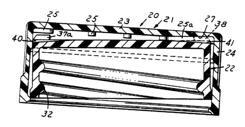
Referring to FIG. l, the child resistant closure 2U
comprises an outer shell 21 and an inner shell 22 telescoped
within the outer shell. The outer shell 21 includes a base wall
23 and a peripheral sx.irt 24. The base wall includes
circumferentially spaced radial projections 25 (FIGS. 4-6).
The projections 25 extend radially inwardly from the area of
juncture of the base wall 23 and skirt 24 and have their inner
ends spaced radially from the center of the shell 21. Projections
25 have planar side surfaces 25a extending axially or
perpendicular to the plane of the top wall of the outer shell
21. Outer shell 21 further includes an indentation 26 defining
an inclined surface 27 that extends radially and forms an acute
angle, on the order of 3.5 degrees with respect to the plane of
the base wall 23. .~s shown in FIG. 4, the inclined surface 27
comprises a planar chordal surface that spans a plurality of
projections 25 which in the chordal area have a greater length
as at 25a and 25b.
Referring to FIGS. 8-11, the inner shell 22 includes
a base wall 30 and a peripheral skirt 31 which in turn has
threads 32 on the inner surface thereof for engaging the threads
33 on a container 34. The skirt 31 further includes a radial
flange 35 adapted to engage beneath a bead 36 on the lower end
of the skirt 24 of the outer shell 21 (FIGS. 1, 7).
The base wall 3U of the inner shell 22 includes a
plurality of circumferentially spaced radial projections or
lugs 37 that extend from the area of juncture of the base wall
- 6-
1
CA 02038727 2002-09-12
30 and skirt 31 radially inwardly and have their ends
spaced from the axis of the shell 22. Each projection 37
includes a radial and axial surface 37a which is adapted to
be engaged by the projections 25 on the outer shell 21 when
the closure is threaded on the container. Each projection
37 also includes a radially inclined cam surface 38 which
is adapted to be engaged by the projections 25 on the outer
shell 21 during the unthreading of the closure in the event
that insufficient axial force is applied to provide
engagement between the projections 25 and the projections
37. The outer shell and inner shel:l_ are preferably made of
plastic material such as polypropylene.
The aforementioned construction is old and well known
as disclosed in the aforementioned British Patent
1,529,999, except for the :inclined indentation 26 and
associated surface 27 on the outer shE:ll and the addition
of a plurality of circumferentially spaced grooves 40 on
the outer inner shell 22. The grooves 40 extend radially
and are spaced between t:he projections 37 t.o define an
inclined base surface 41 that forms an acute angle with the
plane of the base wall 30 of the shell 22, preferably in
the order of about 3.5 degrees with respect to the plane of
the base wall. Each groove 40 also has a planar axial side
surface 42 which is an extension of the axial surface 37a
on the adjacent lug 37 and an opposite planar axial side
surface 43.
By this arrangement, the closure is applied to the
container in the normal fashion and during the application
an axial load is applied by appropriate machinery to cause the
4~ ~ ~~
outer shell 21 to move axially toward the inner shell engaging
the projections 25 on the outer shell with the surfaces 37a of
projections 37 on the inner shell to tighten the closure onto
the container. If a child or the like were thereafter to rotate
the outer shell 21 in the direction to unthread the closure
from the container, the cam surfaces 38 would normally cam the
outer shell away from the inner shell preventing engagement of
the projections.
In accordance with the invention, a downward force to
a portion of the periphery of the outer shell will cause the
projections 25a, 25b on the outer shell 21 to engage the grooves
40 on the inner shell 22 allowing torque to be transmitted from
the outer shell 21 to the inner shell 22 so that the closure can
be removed. To facilitate operation, suitable markings or
indicia are applied to the outer surface of the base wall
indicating to the user the location where a downward force
should be applied, as shown in FIG. 2.
Applying downward force in this location will cause
the outer closure 21 to tilt with respect to the inner closure
22. This will allow one or more projections 25 from the inside
top of the outer closure 21 located below the top plane of the
inner closure 22, and into inclined area 41 where the
perpendicular face of the projection 25 can contact the surface
42 generally perpendicular to the tap plane of the closure.
Because there is contact between surfaces on the outer closure
21 and inner closure 22 that are generally parallel to each
other and to the vertical axis of the closure, torque can be
_g_
~~~~jr~~.~
transmitted directly from the outer closure 21 to the inner
closure 22.
Applying downward force uniformly to the top of the
outer closure 21 or at any other location than that indicated
as being above the inclined surface area, will require the user
to exert sufficient downward pressure to overcome the tendency
for the projections on the inside top of the outer to cam over
the inclined surface 38 of the lugs 37 on top of the inner
closure 22.
In the form of outer shell shown in FIG. 14, a second
planar and chordal surface 27a is provided on the outer shell
21a so that the closure can be tilted at two positions.
In the form shown in FIG. 15, the outer shell 21b
includes an inclined surface 27b between each projection 25,
all the surfaces 27b lying in a common frustoconical surface.
Thus, in this form, the outer shell 2Ib can be tilted at any
position.
In both of the forms shown in FIGS. 14 and 15, the
inner shell 22 remains the same.
It can thus be seen that there has been provided a
child resistant closure of the aforementioned type which m
more user friendly; wherein the amount of axial force require
to remove the closure is not solely dependent upon tnN
interengagement of the sides of the projections to provide the
desired break-away torque necessary to loosen the closure; an,~
wherein the closure can be removed either by a tilting of ",
-9-
outer shell relative to the inner shell or by axial movement
only of the outer shell relative to the inner shell.
-10-