Language selection

Search

Patent 2038756 Summary

Third-party information liability

Some of the information on this Web page has been provided by external sources. The Government of Canada is not responsible for the accuracy, reliability or currency of the information supplied by external sources. Users wishing to rely upon this information should consult directly with the source of the information. Content provided by external sources is not subject to official languages, privacy and accessibility requirements.

Claims and Abstract availability

Any discrepancies in the text and image of the Claims and Abstract are due to differing posting times. Text of the Claims and Abstract are posted:

  • At the time the application is open to public inspection;
  • At the time of issue of the patent (grant).
(12) Patent Application: (11) CA 2038756
(54) English Title: METHOD AND APPARATUS FOR FORMING FLUFF PADS FOR DIAPERS AND THE LIKE
(54) French Title: METHODE ET APPAREIL DE FORMATION DE TAMPONS PELUCHEUX POUR COUCHES ET ARTICLES ANALOGUES
Status: Dead
Bibliographic Data
(52) Canadian Patent Classification (CPC):
  • 19/1
(51) International Patent Classification (IPC):
  • D01G 25/00 (2006.01)
  • A61F 13/15 (2006.01)
  • D04H 1/00 (2006.01)
(72) Inventors :
  • HERTEL, JAMES E. (United States of America)
  • MERKATORIS, JOHN R. (United States of America)
  • CRAIG, GRANTLAND A. (United States of America)
(73) Owners :
  • HERTEL, JAMES E. (Not Available)
  • MERKATORIS, JOHN R. (Not Available)
  • CRAIG, GRANTLAND A. (Not Available)
  • PAPER CONVERTING MACHINE COMPANY (United States of America)
(71) Applicants :
(74) Agent: FINLAYSON & SINGLEHURST
(74) Associate agent:
(45) Issued:
(22) Filed Date: 1991-03-21
(41) Open to Public Inspection: 1991-10-26
Availability of licence: N/A
(25) Language of filing: English

Patent Cooperation Treaty (PCT): No

(30) Application Priority Data:
Application No. Country/Territory Date
514,199 United States of America 1990-04-25
620,627 United States of America 1990-12-03

Abstracts

English Abstract


METHOD AND APPARATUS FOR FORMING
FLUFF PADS FOR DIAPERS AND THE LIKE

ABSTRACT OF THE DISCLOSURE:
A method and apparatus for forming fluff pads and the
like wherein fluff providing material webs are introduced into
separate hammermills and then delivered a plurality of ducts
through a moving screen under vacuum and wherein the ducts are
characterized by reverse bends to densify the particle stream at
the outside of the curvature for generally perpendicular
deposition on the screen.


Claims

Note: Claims are shown in the official language in which they were submitted.


The embodiments of the invention in which an exclusive
property or privilege is claimed are defined as follows:

1. A fluff former comprising a frame providing a
longitudinally extending path, a drum mounted in said frame
having a circumferentially extending screen, means for rotating
said drum one direction, a vacuum source associated with said
frame for maintaining a vacuum inside said drum, fluff mill
means in said path on one side of said drum to provide with said
vacuum source a fluff particle stream, a take-away conveyor in
said path on the other side of said drum, a plurality of
longitudinally extending fluff delivery ducts on said frame in
said path each having a first end connected to said mill means
and a second end communicating with said screen, each said
duct adjacent said second end including a generally C-shaped
section to change the direction of flow of said stream, said
generally C-shaped section having an inner side and an outer
side, said inner side being elongated in the direction of drum
rotation and said outer side extending generally perpendicularly
of said screen whereby the outer side densifies the fluff
particle stream thereagainst to achieve fluff particle deposit
on said screen.
2. The fluff former of claim 1 in which said mill
means includes a plurality of separate rotor-equipped chambers,
means upstream of said mill means for feeding web means to each
chamber, each of said plurality of delivery ducts being
connected to a separate chamber.

- 11 -


3. The structure of claim 1 in which each generally
C-shaped section is characterized by a radius of curvature which
is at least about four times the duct height measured in the
direction of the radius of curvature.
4. A fluff former comprising a frame providing a
longitudinally extending path, a drum mounted in said frame
having a circumferentially extending screen, means for rotating
said drum one direction, a vacuum source associated with said
frame for maintaining a vacuum inside said drum fluff mill means
in said path on one side of said drum to provide with said
vacuum source a fluff particle stream, a take-away conveyor in
said path on the other side of said drum, a plurality of
longitudinally extending fluff delivery ducts on said frame in
said path each having a first end connected to said mill means
and a second end communicating with said screen, each said duct
adjacent said second end including generally C-shaped section to
change the direction of flow of said stream, said generally
C-shaped section having an inner side and an outer side, said
inner side being elongated in the direction of drum rotation and
said outer side extending generally perpendicularly of said
screen whereby the outer side densifies the fluff particle
stream thereagainst to achieve fluff particle deposit on said
screen, each duct having a cross-sectional area such as to
maintain flow velocities in the range of about 40 to about 200
feet per second.

- 12 -


5. A fluff former comprising a frame providing a
longitudinally extending path, a drum mounted in said frame
having a circumferentially extending screen, means for rotating
said drum one direction, a vacuum source associated with said
frame for maintaining a vacuum inside said drum, fluff mill
means in said path on one side of said drum to provide with said
vacuum source a fluff particle stream, a take-away conveyor on
in said path on the other side of said drum, a plurality of
longitudinally extending fluff delivery ducts on said frame in
said path each having a first end connected to said mill means
and a second end communicating with said screen, each said duct
adjacent said second end having a generally C-shaped section
having first in the direction of stream flow a substantially
uniform cross section leg portion and thereafter adjacent said
second end a foot-like portion elongated in the direction of
drum rotation, said foot-like portion having a wall first in the
direction of drum rotation extending generally perpendicularly
of said screen.
6. The structure of claim 5 in which said fluff mill
means includes a plurality of separate rotor equipped chambers,
means upstream of said fluff mill means for feeding web means to
each chamber, each of said plurality of delivery ducts being
connected to a separate chamber.
7. The structure of claim 6 in which each rotor
equipped chamber is equipped with its own drive motor.

- 13 -


8. A fluff former comprising a frame providing a
longitudinally extending path, a drum mounted in said frame
having a circumferentially extending screen, means for rotating
said drum one direction, a vacuum source associated with said
frame for maintaining a vacuum inside said drum, fluff mill
means in said path on one side of said drum to provide with said
vacuum source a fluff particle stream, a take-away conveyor on
in said path on the other side of said drum, a plurality of
longitudinally extending fluff delivery ducts on said frame in
said path each having a first end connected to said mill means
and a second end communicating with said screen, each said duct
adjacent said second end having a generally C-shaped section
having inner and outer ends, said section having first in the
direction of stream flow a substantially uniform cross section
leg portion and thereafter adjacent said second end a foot-like
portion elongated in the direction of drum rotation, each duct
in the uniform cross section thereof is equipped with deflector
means for concentrating the deposit of fluff particles centrally
of the width, each said duct adjacent said deflector means being
equipped with air supply openings, said openings being
positioned slightly downstream of the upstream end of each
deflector.

- 14 -


9. A fluff former comprising a frame providing a
longitudinally extending path, screen means movably mounted on
said frame in said path, means for moving said screen means in
one direction, a vacuum source associated with said frame for
maintaining a vacuum on one side of said screen means, fluff
mill means operably associated with said frame to provide with
said vacuum source a fluff particle stream, a plurality of
longitudinally extending fluff delivery duct on said frame in
said path each having a first end connected to said mill means
and a second end communicating with said screen means, each said
duct adjacent said second end having a generally C-shaped
section having first in the direction of stream flow a
substantially uniform cross section leg portion and thereafter
adjacent said second end a foot-like portion elongated in the
direction of movement of said screen means, said foot-like
portion having a wall first in the direction of movement of said
screen means extending generally perpendicularly of said screen
means.
10. The structure of claim 9 in which said screen
means is a drum, said vacuum source maintaining a vacuum within
said drum.
11. The structure of claim 9 in which said fluff mill
means includes a plurality of separate rotor equipped chambers,
means upstream of said fluff mill means for feeding web means to
each chamber, each of said plurality of delivery ducts being
connected to a separate chamber.

- 15 -


12. The structure of claim 11 in which each
rotor-equipped chamber is equipped with its own drive means.
13. The structure of claim 11 in which said rotors are
mounted on a common drive shaft and enclosed in a common
housing, barrier plates spaced axially of said drive shaft and
connected to said housing to provide said chambers.
14. The structure of claim 9 in which each duct has a
cross-sectional area such as to maintain flow velocities in the
range of about 40 to about 200 feet per second.
15. The structure of claim 9 in which each generally
C-shaped section is characterized by a radius of curvature which
is at least bout four times the duct height measured in the
direction of the radius of curvature.
16. The structure of claim 9 in which each duct in the
uniform cross section is equipped with deflector means for
concentrating the deposit of fluff particles centrally of the
width, said duct adjacent said deflector means being equipped
with air supply openings.
17. The structure of claim 16 in which said openings
are positioned slightly downstream of the upstream end of each
deflector.

- 16 -


18. A fluff former comprising a frame providing a
longitudinally extending path, screen means movably mounted on
said frame in said path, means for moving said screen means in
one direction, a vacuum source associated with said frame for
maintaining a vacuum on one side of said screen means, a fluff
mill operably associated with said frame to provide with said
vacuum source a plurality of separate fluff particles streams, a
plurality of longitudinally extending fluff delivery ducts on
said frame in said path each having a first end connected to
said mill and the second end communicating with said screen
means, said fluff mill means including a plurality of
rotor-equipped chambers, one each of said ducts being coupled at
the first end thereof to one of said chambers and means for
introducing fiber-producing web material separately into each
chamber.
19. The structure of claim 18 in which said fluff mill
means includes a housing, a drive shaft extending through said
housing, a plurality of said rotors mounted on said drive shaft
in axially spaced relation, and a barrier plate between each
pair of rotors and connected to said housing to define said

chambers.

- 17 -

Description

Note: Descriptions are shown in the official language in which they were submitted.


~3~

D--452A


METHOD AND APPARATI~ FOR FORMING
FLUFF PADS FOR DIAPERS AND THE LIKE


BAC~Q~lD A~ SUMMARY OF THE INVENTION:
This invention relates to a method and apparatus for
forming fluff pads for diapers and the like, and more
particularly, to apparatus employing a moving screen -- as on a
rotating drum and novel ductwork. Fluff forming screens have
been known for a considerable time -- see, for example, co-owned
9/35//Lf~-J~
U.S. Patent 3, 599, 293 . This invention provides novel means for
depositing the fluff particles on the screen.
Typical fluff forming systems, both drum and wire, use
large "boxes" positioned over forming wires. These boxes, or
forming hoods, are supplied with a fiber/air mixture ~typically
.005 to . 03 lb. fiber cubic foot of air~ which is then drawn
toward the screen through air rlow and gravity forces.

. ~ ~


'

20387~

Problems often encountered in these ba~ic forming
methods are:
- uneven fiber density in the pad;
- "clumping" due to air turbulence; i.e., formation of
"fiber balls" prior to laydown;
- clumping due to rolling or picking of the pad by high
velocity air tangent to the screen; i.e., air scrubbing off part
of the pad and redepo~iting it as a clump.
To obtain a high pad integrity it is necQssary to have
a high air flow through the pad during forming. However, the
large volume of the forming box allows air turbulence and
instability and, hence, the clumping problemQ described a~ove.
These instabilities are usually seen as eddie~ or pulsing in the
forming box. ~I?J~ 3~)
One method (U. S. Patent 4,494,278) for reducing or
eliminating these problems was to mill the ~luff and air convey
it to the forming hood with general disregard for clumping.
Then, the fiber/air mixture was introduced into an agitated box
over the forming wire. The ~iber~ were then redistributed and
sifted through a screen before falling onto the w$re to form the
pad.
In other formers, fiber~ are conveyed to hopper~ which
feed secondary milling rotors immediately above ths forming
area. Thi~ and the '278 method both overcome the problem~
listed b~t require significantly more equipment than the simple
forming box.
In one aspect the invention include~ a frame providin~

2~38756

a longitudinally extending path, a drum mounted on the frame
having a circumferentially extending screen, means for rotating
the drum in one direction, a vacuum source associated with the
frame for maintaining a vacuum inside the drum, fluff mill means
in the path on one side of the drum to provide (with the vacuum
source) a fluff particle stream, a take-away conveyor in the
path on the other side of the drum, a plurality of
longitudinally extending fluff delivery ducts on the frame in
the path each having a first end connected to the mill means and
a second end communicating with the screen, the duct second end
including a reverse bend section elongated in the direction of
drum rotation whereby the outer side of side reverse bend
intensifies the fluff particle steam thereagainst to achieve
fluff particle deposit on the screen without substantial
turbulence.
In another U.S. patent (No. 4,904,440) dealing with pad
formation, the output of the hammermill is split into a
plurality of stream~ for vacuum-induced delivery to a drum. In
another aspect of this invention, we split the material input to
separate hammermill means and this results in several benefits
over a single mill with a splitting device at the outlet.
1. Allows independent control of airflow
and vacuum for each forming chamber
without affecting the fluff separation ratios.
2. Prevents mixing so that a different fluff
material can be accurately layered into the
forming pad.
3. Trim pieces (i.e., from the pad leg cutouts)
3 --

203875~

can bQ introduced into a single mill chamber
and hence directed to a specific layer in the
pad.
4. Allows us~ of long length ~luf~ fibers li.~.,
synthetic fibers) without the problems
associated with buildup on the leading edges of
the splitting devices.
BRIEF_DESC~ QN OF ~RAWING:
The invention iQ described in con~unction with an
illustrative embodimQnt in the accompanying drawing, in which --
FIG. 1 is a side elevational view of apparatus employedin thQ practice~ o~ the invention;
FIG. 2 i8 an end elevational view of the apparatus of
FIG. l;
FIG. 3 is an enlarged sectional view taken along the
line 3-3 o~ FIG. l;
FIG. 4 ia a view similar to FIG. 1 but o~ a modified
form o~ apparatus; and
FIG. S is a sectional view along the line 5-5 of FIG.
4.
PEI~Ir,E~ DE~ÇR~ Q~:
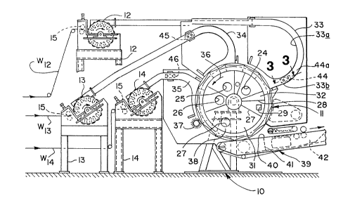
R~erring first to FIG. 1, the numeral 10 de~ignates
generally a ~ram~ Sor rotatably supporting an annular drum
generally deqignated 11 and ~hich i-~ operably as~ociated with
~: ~ 25 hammermills 12, 13 and 14 suitably supported on frames 12', 13'
and 14'. Each mill 12-14 is ~ed by its own web a~ at W12,
W13 and W14 via pull rolls lS ~n each frame 12'-14'. The

- 4 -

2~3g~s~

pulp webs are converted to fluf~ fibers and delivered via ducts
(to be described hereinafter) to the drum 11.
Moro particularly, the annular drum 11 inciudes a
spider 16 (se~ the left hand portion o~ FIG. 2) which is
supported by a drive shaft 17 carried in ball bearing pillow
block~ as at 18 and 19 -- all being part of the frame 10. A
drive is indicated schematically at 20 in the form o~ a sheave
operably associated with a drive motor and belt (not shown).
Still referring to FIG. 2 the inner wall of the annular
drum 11 as at 21 is sealingly related to a plenum 22, portions
of which are exhausted by a vacuum connection generally
designated 23. Only one such connection is shown in FIG. 2 bu~
in the illustrated embodiment as seen in FIG. 1, we provide four
vacuum ports as at 24, 25, 26 and 27. Radial vanes are provided
at a plurality of angularly related positions, a first of which
is designated 27. The vane 27 in the stationary plenum 22 along
with a second vana 28 defines a chamber for introducing air
through the inlet port 29 which is used for cleaning the
screen. Th~ scre~n provided in the annular drum is
schematically representQd at 30 in FIG. 2. Chambers as at 31
and 32 (now referring to FIG. 1) and which rlank tho chamber
with the air inlot opening 29 are unused, being neither under
pressure nor vacuum.
Streams of fluff particles are introduced through t~
ducts 33, 34 and 35 which ars relatively elongated at their
- outlet ends in the direction of screen movement, i.e., rotatlon

2 03~ 75 v

of the annular drum ll as indicated by the arrow in the central
part of FI~. l and which is designated 36.
After the fluff ha5 been deposited on the screen 30 of
the annular drum ll from the thre~ ducts 33-35, the now-formed
fluff pads pass by a scarfing wheel 37 rotatably mounted on the
frame in conventional fashion.
WQ provid~ a baffle for the vacuum a~ at 38 to reduce
the holding forc~ on the pads so that thQ padq can be stripped
by a takeaway conveyor 39 movably mounted on the frame lO. The
takeaway conveyor 39 include~ an endless belt 40 which
advantageously is foraminous or othQrwisQ air permeable to allow
vacuum to draw tho pads from th~ drum ll. A first vacuum
chamber i~ provided a~ at 41 and a second vacuum chamber as at
42 as part of the takeaway conveyor.
We have found the struc~ure of the fluff-supply ducts
to be especially advantageous in achieving the benefits of the
invention. More particularly, in order to stabilize the air
mas~ in the forming section, the fiber/air mixture is separated
into multiple ducts in route to the pad former. This allows
smaller cros-~-~ection~ and avoids unstabl~ air behaviors.
Prior to fiber laydown the duct curvature causes the
fiber/air mixture to ~tratify; i.e., the fiber density is hig~er
than air and thus th~ fiber concentration at the outside of the
curve is greater than than at the inside of the curve. The h
concentration portion of the flow i~ directed at a small angle
from normal (approximately perpendicular) to the forming wire

2~3~75~


(pad form) and at high velocity without turbul~nt mixing. The
lower concentration portion (inside track) is slowed down by an
expansion of the duct area. Design parameters for the duct
shapes can be ~enerally described as:
- cross sectional areaq are set to maintain flow
velocities in the ranga of 40 to 200 feet per second;
- changes in direction are gradual; i.e., radii of
curvature are typically greater than four times the duct height;
- high concentration flow area (outside o~ duct curve)
iq directed roughly normal to tho forming surface;
- ~inal shapo of tho "insido" cur~e follows natural
expansion o~ air flow stream into chamber .
In addition to the improved air ~low stability, th~
invention also offers the benefitq o~;
- space between separate forming section~, i.e., duct
outlet~, for introduction of superabsorbent powder into a
specific layer o~ the pad;
- potential to make multi layer pads o~ dissimilar
fluff material~;
- ability to tailor forming air flows for start o~ pad
formation (high volume/low pressure) separatQ ~rom ond of pad
for~Ation ~low volume/high preq~ure).
~uct Construction
We have ~ound it particularly advantageous to construc~
the delivery duct work in two dif~erent cross sectional area~
ad~acent ths discharge end -- as can be readily appreciated ~ro~
a consideration o~ FIG. 1. There each duct 33-35 i~ seen to

17J ~ 3 8 Y~ 3

includ2 a reverse bend or ~TenQral C-~hape with the bottom o~ the
C-~hape b~ing r~lativ~ly elongated and op~n to th~ ~creen 30 on
tha drum 11. ~ora particularly the inner side o~ each du~t a
at 33a (r~lative to thQ duct 33~ is gen~rally C-~haped wherea~
the outer side as at 33b i~ only partially C-shaped to provide
the discharg~ end o~ th~ duct worlc with an oporling a~ at 43
~acing the screenO A~ m~ntioned previously thQ outer side 33b
of the reverse b~nd section aehieves a denYi~ication of the
particl~ ~tream adjacent to itsel~ so as to d~velop a deposition
of the~ flufr paxticle~ on the screen without sub tantial
turbulsnc~3 .
Preferably, WQ include within the duc1:s de~lector means
as at 44, 45 and 46 r~lative to th~ duct~ 33-35, respectively.
Typical defl~ctor3 ara seen at 44 ln FIGS. 2 and 3 and include
plat2~i extending generally lon~itudillally o~ the duct~ and
converg~nt relativ~ to each other :in thE~ direction o~ the ~luf f
particl~ strea~. Air i~ drawn in l:hrough opening~ a~ at 44a
relativa to thQ de~l~ctor maans 44 and imil~r openings ara
pro~ided ~or the dafl~ctors 45 and 4S. The~ de~lectox~ 44-46
advantageou~ly conc~ntrat~ the deposition o~ rlu~ particle~
centrally of th~ width o~ tha diaper shap~ which i~ lth~ area
most likely ~or rec~ipt for ~xcreta o~ in~ant~ and incontinen~c
adult~ .
Q~z~
2 5 In th~ operatlon o~ the invention, th~ pulp web~3 are
milled into ~luf~ partic:le~ by the hammerm~ 12-14 and drawn
separately through ducts 33-3S under tha influ~ncQ o~ vacuum

--- ` 2~387~


applied as at 23 (see FIG. 2) to a stationary plenum 22. Moving
past the open Qnds of the ducts as at 43 relativ~ to the duct 33
(see FIG. 1) is a screen which advantageously may be in the form
o~ an annular drum 11. Suitable forms to shape the dQposited
fluff particle~ into hourglass shaped pads are provided as part
o~ the screQn 30.
The signi~icant ~actor WQ have found is that turbulence
iQ eliminated by having a gradual change in direction of the
particle flow by virtue of the curvature at 33b in the leg
portion o~ the duct and then continuing the duct into a
~oot-liXe portion overlying the annular drum 11. This results
in a stratification of the fluf~ particles with the more
concentrated or dense particles being on the outsidQ of the
curve~ or reverse bend so as to impinge upon the screen at a
slight angle to perpendicular.
Embodiment Or FIGS. 4-5
In some instance~, particularly for space conservation,
the embodiment o~ FIGS. 4-5 may be employed. In this
embodiment, the ducts 133-5, drum 111 and takeaway conveyor 139
are substantially the same as in the FIG. 1 embodiment. What is
changed is tho con~truction o~ the hammermill mean-~. As
illustrated the thr~e rotors 112, 113 and 114 are mounted on a
common shaft 147 tse~ FIG. 5). The sha~t is rotated through a
drive 148 from a motor (not shown).
The housing 149 encloses the rotors 112-114 and barrier
plates lS0 and 151 mounted in the housing 149 maintain each

2~387~


rotor 112-114 in a -~eparate chamb~r. As illu~trated at the left
hand portion of FIG. 4 three parent rolls of web material are
provided, one for each chamber. For example, the wèb from
parent roll 152 is directed to the chamber containing rotor 114,
that from parent roll 153 to th~ chamber containing rotor 113
and the web from thQ parent roll 154 i~ delivQred to tha chamber
containing rotor 112. The delivery is effected by pull rolls
115 mounted in the housing 149 with tha three webs from the
parent rolls 152-154 being arranged in sid~-by-side relation.
As indicated previously, tho saparate chambers afford
the opportunity for augmenting the webs by other material, viz.,
recycled trim pieces, synthetic fibers, etc. The invention also
contemplate~ employing a single parent roll with slitter-~ to
develop the three separate webs entering the housing 149.
While in the foregoing specification a detailed
description of an embodiment of the invention has been set do~n
for the purpose of illustration, many variations in the details
hereingiven may be made by those skllled in the art without
departing from the spirit and SCOpQ of the invention.


-- 10 --

Representative Drawing
A single figure which represents the drawing illustrating the invention.
Administrative Status

For a clearer understanding of the status of the application/patent presented on this page, the site Disclaimer , as well as the definitions for Patent , Administrative Status , Maintenance Fee  and Payment History  should be consulted.

Administrative Status

Title Date
Forecasted Issue Date Unavailable
(22) Filed 1991-03-21
(41) Open to Public Inspection 1991-10-26
Dead Application 1993-09-21

Abandonment History

There is no abandonment history.

Payment History

Fee Type Anniversary Year Due Date Amount Paid Paid Date
Application Fee $0.00 1991-03-21
Owners on Record

Note: Records showing the ownership history in alphabetical order.

Current Owners on Record
HERTEL, JAMES E.
MERKATORIS, JOHN R.
CRAIG, GRANTLAND A.
PAPER CONVERTING MACHINE COMPANY
Past Owners on Record
None
Past Owners that do not appear in the "Owners on Record" listing will appear in other documentation within the application.
Documents

To view selected files, please enter reCAPTCHA code :


To view images, click a link in the Document Description column. To download the documents, select one or more checkboxes in the first column and then click the "Download Selected in PDF format (Zip Archive)" or the "Download Selected as Single PDF" button.

List of published and non-published patent-specific documents on the CPD .

If you have any difficulty accessing content, you can call the Client Service Centre at 1-866-997-1936 or send them an e-mail at CIPO Client Service Centre.


Document
Description 
Date
(yyyy-mm-dd) 
Number of pages   Size of Image (KB) 
Representative Drawing 1999-07-09 1 26
Drawings 1991-10-26 2 100
Claims 1991-10-26 7 246
Abstract 1991-10-26 1 16
Cover Page 1991-10-26 1 16
Description 1991-10-26 10 355