Note: Descriptions are shown in the official language in which they were submitted.
J ~
-- 1
IN-FURNACE SLAG LEVEL MEASURING METHOD AND APPARATUS
THEREFOR
BACKGROUND OF THE INVENTION
The present invention relates to an in-furnace slag
level measuring method for predicting the occurrence of
slopping in a refining period in a convertor, and an
apparatus therefor.
Slag floating on a surface of molten metal in a
convertor in a refining period foams according to
factors for refining in the convertor, that is,
according to factors such as the composition and
viscosity of the slag, the oxygen content of the slag,
etc. When the foaming of the .slag progresses
excessively, so-called slopping occurs to have a bad
influence on the composition of the molten metal, the
total yield of the refined product, etc. When such
slopping progresses further, problems arise as to the
reduction of workability, the reduction of the calorie
of exhaust gas, the worsening of working environment
such as production of red smoke, the damage of the
apparatus, etc.
On the other hand, use of a slag foaming
suppressing agent or suppressing of the amount of oxygen
supplied for a lance to thereby reduce the amount of
generated exhaust gas is considered from the point of
2 ~ 3 ,~ ~ 2 ~
-- 2
1 view of prevention of the slopping of slag. However,
use of an excessive amount of the slag foaming agent
brings the following two disadvantages; increase in
cost; and worsening of thermal efficiency caused by
lowering of in-furnace temperature. Further,
suppressing of the amount of supplied oxygen brings
elongation of operation caused by reduction of reaction
efficiency, that is, it brings worsening of the
productivity.
Accordingly, not only prediction of slopping but
grasping of the slag level in the convertor
quantitatively and accurately for the proper operation
of the convertor are necessary for the prevention of the
occurrence of slopping.
Therefore, a technique for measuring the slag level
in the convertor quantitatively has been considered. As
the conventional technique, a radar type level meter
using microwave capable of propagating straight even
under the measuring environment that dust or flame is
present in the convertor has been considered chiefly.
An example of the conventional slag level meter
using a microwave radar has been disclosed in Japanese
Patent Unexamined Publication No. Sho-63-21584. In
the disclosed slag level meter, a microwave FMCW type
radar antenna for a carrier frequency of about 10 GHz
is fixed to an upper portion of a body of the convertor
~3&2~
-- 3 --
1 to transmit a microwave toward the surface of slag
through the antenna. The propagation time required for
the reciprocating motion of the microwave signal between
the antenna and the slag surface, that is, the time
from the point of time when the microwave signal is
transmitted through the antenna to the point of time
when the microwave signal is received through the
antenna after reflected on the slag surface, is
measured and converted into a distance. However, the
conventional slag level meter has a disadvantage in that
a shortage of sensitivity may arise in the FMCW type
radar in the case where the surface of foamed slag is
low in reflectivity with respect to such a microwave.
To solve the problem in the FMCW type radar, an
improved slag level meter has been proposed in Japanese
Patent Unexamined Publicatlon No. Hei-2-98685 filed by
the Assignee of the present invention. In the improved
slag level meter, a pseudo random signal processing type
microwave radar using a microwave with a carrier
frequency of about 10 GHz is employed. In the slag level
meter, a water-cooled antenna attached to an end of a
water-cooled waveguide is inserted down into the
convertor and then fixed. The propagation time required
for the reciprocating motion of a microwave between the
water-cooled antenna and the slag surface, that is, the
time from the point of time when the microwave is
, 2 ~
1 transmitted through the water-cooled antenna to the
point of time when the microwave signal is received
through the water-cooled antenna after reflected on the
slag surface, is measured and converted into a
distance.
In those conventional techniques, it is necessary
to secure an antenna fixture place or an antenna
insertion hole in a hood being in the upper portion
of the convertor, because the antenna must be provided
in any case. However, space assignment for attaching
the antenna to the hood is so complex that an increase
in the equipment cost is brought, because attendant
equipment of the convertor, such as a mainlance, a
sublance, a sub-material supply hopper, a dust, etc.
is provided with high density. In particular, in the
case where a general convertor is rebuilt to attach the
antenna thereto or in the case where a boiler piping is
provided to the hood to recycle exhaust heat for the
purpose of energy saving required in the recent years,
the rebuilding of the hood is high in cost.
SUMMARY OF THE INVENTION
An object of the present invention is to provide
an in-furnace slag level measuring method and an
apparatus therefor, in which a hole which serves as a
sublance insertion hole for inserting a sublance into a
2 ~ 3 `~? ~ t
-- 5 --
1 convertor at the last stage of a refining period is
commonly used as an antenna insertion hole so that the
hole is used alternately for an antenna and sublance in
the refining period in the convertor.
Another object of the present invention is to
provide an in-furnace slag level measurement apparatus
which can measure a slag level accurately and
continuously by using a low-cost apparatus without
influence of the measurement environment in which dust
or the like is present.
It is another object of the present invention to
provide an in-furnace slag level measuring apparatus in
which the in-furnace slag level is measured by using
pseudo random signals such as Bar~er codes or the like.
It is a further object of the present invention to
provide an in-furnace slag level measuring apparatus
in which a slag level position in a furnace can be
measured with high accuracy even when the change of the
slag level in the furnace is severe.
According to an aspect of the present invention,
in the in-furnace slag level measuring method and
apparatus, a sublance and an antenna in a slag level
meter (microwave radar) are alternately inserted into a
common hole in a hood of a convertor in a short time.
25 Accordingly, equipment for the method and apparatus is
simple in construction because the two purposes can
~ ~ p3 ,~ `;?~ ~ ~J
-- 6 --
1 be attained by one common hole. In particular, in the
case where a general convertor having a sublance
insertion hole is used, the rebuilding thereof is
easier. The state of slag can be grasped exactly to
predict the occurrence of slopping accurately by
measuring the slag level while inserting the antenna
into the convertor at the first and second (middle)
stages of the refining period. Accordingly, slopping
can be prevented by a slopping suppressing means. As a
result, a refining procedure with good efficiency can be
provided in the convertor. Further, a sublance is
inserted into the convertor at the last stage of the
refining period to perform measurement of the
temperature of a molten metal, picking-up of a molten
metal sample, picking-up of a slag sample, etc. through
the sublance inserted into the convertor.
According to another aspect of the invention, the
in-furnace slag level measuring method and apparatus
has a sublance attached to a beam in the upper portion
of a convertor so as to be both rotatable and up/down
movable, a water-cooled antenna attached to the beam in
the upper portion of the convertor so as to be both
rotatable and up/down movable, and a microwave radar
connected to the water-cooled antenna. The sublance and
the water-cooled antenna can be placed alternately so
that one of the two is inserted to the convertor
~~J ~ J ë~
-- 7 ~
1 through a common hole of a hood of the convertor
Because the sublance and the water-cooled antenna are
respectively attached to the beam so as to be rotatable
and up/down movable, the positions of the two can be
exchanged with each other by rotating the two. That
is, the sublance or the water-cooled antenna can be
inserted into the convertor according to the necessity.
According to a still further aspect of the present
invention, the microwave radar has a transmission
antenna and a reception antenna inserted into the
furnace, to generate a slag level measured value signal
by calculating the distance between the antennas and the
slag surface on the basis of a microwave
signal transmitted through the transmission antenna,
lS reflected on the slag surface in the furnace and
received through the reception antenna.
According to a further aspect of the present
invention, the microwave radar measures the distance to
a slag surface through the steps of: transmitting a
carrier phase-modulated on the basis of a first pseudo
random signal toward a slag surface; obtaining a time-
series pattern of a detection signal by detecting a
carrier obtained by multiplying a reception signal
reflected on the slag surface by a second pseudo random
signal; obtaining a time-series pattern of a
multiplication value by directly multiplying the first
,J~3~3
-- 8
1 and second pseudo random signals by each other; and
measuring the time difference between the time-series
pattern of the detection signal and the time-series
pattern of the multiplication value. Accordingly, the
following effects can be attained.
(1) Because of non-contact measurement, durability of
sensor portions such as an antenna, etc. can be secured
and, at the same time, both the device attachment and
maintenance can be simplified.
(2) Because of continuous measurement, a measurement
of high response can be made.
(3) Because spectrum-diffused signals using pseudo
random signals are used, both the noise reduction and
signal emphasis can be attained by application of a
correlation processing using a reference pseudo random
signal in the reception portion. Accordingly, the wave
reflected on a slag surface having a low reflectivity
can be detected sensitively, so that the measurement can
be used for the purposes.
(4) Because the high-speed signal conventionally used
for a measurement can be converted into a low-speed
signal by a circuit relatively simple in construction
according to the invention, a low-cost and small-size
apparatus can be provided. Further, adjustment is made
easily.
1 As means for detecting a carrier reflected on the
slag surface and subjected to a correlation processing
after reception to obtain a detection signal, an in-
phase component and a quadrature component as to the
phase of the transmission carrier are extracted from
the carrier after the correlation processing. The
components are respectively squared through low-pass
filters and then added to each other to obtain a
detection signal.
Accordingly, the slag surface can be detected very
sensitively.
A carrier phase-modulated with a first pseudo
random signal is transmitted to a target and a reception
signal reflected on the target is subjected to a
correlation processing by using a second psuedo random
signal having the same pattern as the first pseudo
random signal and having a frequency near the frequency
of the first pseudo random signal to thereby obtain
the thus processed carrier. Accordingly, the
measurement time between a detection signal from the
target and a reference signal is very greatly enlarged
on a time axis. Therefore, the distance to the target
can be measured accurately even when the distance is
short. Further, the necessary signal reflected on the
target as a subject of the measurement can be clearly
discriminated/separated from unnecessary signals
f~ 3 7 ~r~
-- 10 --
1 reflected on Gther matters than the target surface, on
the time axis in which the detection signal is
generated. Accordingly, the slag level in the furnace
can be measured stably even under measurement
environment of narrow space such as the inside of the
furnace in which unnecessary reflected signals will be
generated easily, because the unnecessary reflected
signals can be removed.
That is, in the present invention, a first pseudo
random signal and a second pseudo random signal having
the same pattern as that of the first pseudo random
signal and having a frequency slightly different from
the frequency of the first pseudo random signal are
generated by a first pseudo random signal generation
means and a second psueo random signal generation means,
respectively. A spectrum-diffused signal formed by
phase-modulating a carrier on the basis of the first
pseudo random signal is transmitted toward a target by a
transmission means. Then, a reception signal obtained
by receiving the wave reflected on the target by a
reception means is multiplied by the second psuedo
random signal through a second multiplier. When the
modulated phase of the reception signal phase-
modulated with the first pseudo random signal coincides
with the phase of the second pseudo random signal, the
result of multiplication obtained as an output from the
, 2 ~
1 second multiplier becomes an in-phase carrier and is
subject to synchronous detection by a coherent detector
means in the succeeding stage. The detection output is
further signal processed through a detection signal
generation means constituted by a pair of low-pass
filters, a pair of squarers and an adder to thereby
output a pulse-like target detection signal.
However, the first and second pseudo random signals
are equal to each other in the code pattern thereof but
slightly different from each other in the frequency of
the signal generator means. Accordingly, the phase of
the two signals become shifted from each other with the
passage of time after phases of the two signals
coincide with each other (that is, the correlation
output of the two signals takes its maximum value).
When the phases of the two signals are shifted from each
other by one code length or more, the correlation of the
two pseudo random signals is lost. In this condition,
the phase of the carrier obtained as a result of
multiplication of the receptions signal by the second
pseudo random signal becomes random, so that the
frequency band is restricted by the low-pass filters
after synchronous detection by the coherent detector
means in the succeeding stage and it is impossible to
obtain a target detection signal.
When the phase difference between the first and
- 12 -
1 second pseudo random signals becomes just equivalent to
one period of one pseudo random signal after time is
further passed, the phases of the two signals become
coincident with each other again. In this condition,
the correlation output of the two signals takes its
maximum value again so that a pulse-like target
detection signal is obtained again through the coherent
detector means and the detection signal generator
means. Thus, this phenomenon is repeated at regular
time intervals so that a cyclic pulse-like signal can
be obtained as a target detection signal.
On the other hand, the setting of reference time
is necessary for measuring the pointing of time when
the target detection signal is obtained from the
reception signal. Therefore, a time reference signal
for representing the reference time is generated as
follows. The first pseudo random si~gnal is directly
multiplied by the second pseudo random signal is
directly multiplied by the second pseudo random signal
through the first multiplier. Then, a time series
pattern as a result of the multiplication is picked up
through low-pass filter, so that a pulse-like signal
having the same period as that of the target detection
signal is obtained as the time reference signal.
Accordingly, because the time from the point of
time when the time reference signal is generated to the
2~
- 13 -
1 point of time when the target detection signal obtained
frorn the reception signal is generated is proportional
to the propagation time taken for the electromagnetic
wave to move forth and back between the transmission
/reception antenna and the target, the distance between
the transmission/reception antenna and the target can be
calculated form the time difference between the the two
signals.
The aforementioned explanation is formulated as
follows:
Let fl be the repetition frequency of the first
pseudo random signal. Let f2 be the repetition
frequency of the second pseudo random signal. It is now
assumed that the patterns of the two pseudo random
signals are equal to each other and that fl is larger
than f2.
When the period in which the reference signal
obtained on the basis of correlation of the first and
second pseudo random signals transmitted takes its
maximum is replaced by TB, the different in the number
of waves between the first and second pseudo random
signals contained in the period TB is equal to the
number N of one-period waves. That is, the following
equation is obtained.
TB~fl = TB-f2+N
Rearranging the equation,. TB is represented by the
h~q~ 3
- 14 -
1 following equation (1).
TB = N/(fl-f2) .............. (1)
This is, the period TB in which the reference
signal takes its maximum increases a the difference
between the two clock frequencies decreases.
Let ~ be the propagation time from the point of
time when the carrier phase-modulated with the first
pseudo random signal is transmitted to the point of time
when the carrier is received after reflected on the
target. Let TD be the time difference between the point
of time when the pulse-like signal of the target
detection signal obtained by demodulating the reception
signal on the basis of the second pseudo random signal
- and coherently detecting it is generated and the point
of time when the pulse-like signal of the reference
signal is generated. Because the number of waves of
the second pseudo random signal ~enerated in the period
TD is smaller by the number of waves of the first pseudo
random signal generated in the propagation time ~, than
the number of waves of the first pseudo random signal
generated in the period TD, the following equation is
established.
TD~f2 = TD~fl - ~-fl
Rearranging the equation, TD is represented by the
following equation (2).
TD = ~fl/(fl -f2) .......... (2)
~ b~2
- 15 -
1 That is, the period TD is measured as a value
obtained by elongating the propagation time ~ by
fl(fl-f2) times or in other words reducing the
measurement speed by fl(fl-f2) times. Such enlargement
of the measurement time means that the present
invention is essentially suitable for short-distance
measurement.
~ ere, the propagation time ~ is expressed by the
equation:
~ = 2x/v
in which v represents the propagation speed, and x
represents distance to the target.
Accordingly, the following equation (3) is obtained
on the basis of the equation t2).
fl - f2
x = V-TD .... (3)
2fl
In short, the distance x can be measured by
measuring the time difference TD according to the
equation (3).
According to another aspect of the present
invention, since a pseudo random/signal generator is
constituted by a counter, a storage device, and a signal
convertor, any an M-type signal and there pseudo random
- 16 -
1 signal other than an M-type signal, such as a Barker
code, or the like, can be used. When, for example, a
Barker code is used as a pseudo random signal, the
signal reflected on the target can be detected
sensitively by a technique of generating a signal
intermittently through providing a time interval for
each period of the output of the Barker code while
changing the signal sensitivity of the radar with the
passage of time to mask unnecessary reflected signals
temporarily
According to a further aspect of the invention,
the microwave radar uses a technique of suppressing the
change of detection signal strength through adjustment
of signal strength in the receiver to thereby suppress
generation of errors caused by signal saturation and
reduction of the signal level. Accordingly, the slag
level position in the furnace can be measured accurately
even when the strength of the microwave signal reflected
on the slag level changes by the change of the slag
level in the furnace or the like. Further, by
averaging measurement values while neglecting low S/N
measurement values, the slag level position in the
furnace can be measured more accurately even when the
signal level is temporarily reduced by the sudden
change of the slag level.
The above and other objects as well as advantageous
~3~g2~
- 17 -
1 features of the invention will become clearer from the
following description taken in conjunction with the
drawings.
BRIEF DESCRIPTION OF THE DRAWINGS
Fig. 1 is a sectional view typically showing
embodimnt of the present invention;
Fig. 2 is a plan view of Fig. 1;
Fig. 3 is a diagram for explaining the
application period of the slag level meter according to
the present invention;
Fig. 4 is a block diagram showing the configuration
of a microwave radar to be applied to the in-furnace
level meter according to the invention;
Fig. 5 shows waveforms for explaining the operation
of the microwave radar depicted in Fig. 1;
Fig. 6 is a view showing the configuration of the ~-
bit M-type signal generator;
Fig. 7 is a block diagram showing another example
of the configuration of the pseudo random signal
generator;
Fig. 8 is a view showing an example of data in the
storage device depicted in Fig. 4;
Fig. 9 is a view showing the relationship between
the input data and output signal of the signal
convertor depicted in Fig. 4;
2 ~ ?3 ~ ,J 2 ~
1 Fig. 10 is a view of a waveform of the signal
convertor;
Fig. 11 is a timing chart showing the operation of
the receiver in the distance measurer depicted in Fig.1;
Fig. 12 is a block diagram showing another
embodiment of the configuration of the microwave radar
in the invention ;
Fig. 13 is a block diagram showing a further
embodiment of the configuration of the microwave radar
in the invention;
Fig. 14 is a block diagram showing amendment of the
configuration of the signal strength changer;
Figs. 15a and 16b are graph views showing the
operation of the signal strength changer; and
Fig. 16 is a flow chart showing the signal escape
in an average operator.
DESCRIPTION OF THE PREFERRED EMBODIMENTS
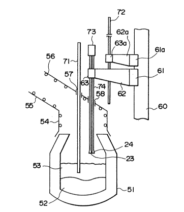
In a convertor shown in Fig. 1, molten metal 53
20 and slag 53 are in a convertor body 51. A hood 54 is
provided at the upper portion of the convertor body 51.
A smoke duct 55 is attached to the hood 54. ~ boiler
piping 56 for recycle exhaust heat is attached to both
the inner wall of the hood 54 and the inner wall of th
25 smoke duct 55. Holes 57 and 58 for insertion of a
mainlance 71 and a sublance 72 are provided in the hood
, 2 ~
-- 19 --
1 54.
As shown in the drawing, a beam 60 is provided near
the convertor. A rotator 61 constituted by an electric
motor is attached to the beam 60. The rotator 61 is
linked with a hinge 62 to rotate it. A lift 63
constituted by an electric motor is attached to an end
of the hinge 62.
A microwave radar ~3 is connected to transmission
and reception antennas 23 and 24 through a waveguide ~4
which is supported by the lift 63 so that the vertical
position thereof is controlled.
Accordingly, the vertical position of the
waveguide ~4 is controlled by the lift 63 and the
position thereof in a two-dimensional plane is
controlled by the rotator 61.
The mechanism for supporting the sublance 72 is
the same as that for supporting the waveguide. That is,
a rotator 61a is attached to the beam 62 and linked with
a hinge 6Za to rotate it. A lift 63a is attached to an
end of the hinge 62a, so that the sublance ~2 is
supported by the lift 63a to control the vertical
position thereof.
In the following, a technique for alternately
inserting the sublance 72 and the antennas 23, 24 into
the furnace is described. From ignition to the best
carbonization period through the slag melting period,
~ ~ 3 !J ~ 2 ~
- 20 -
1 the antennas 23 and 24 of the microwave radar 73 are
inserted into the convertor to measure the slag level to
thereby predict slopping. Thereafter, in the low carbon
period, the sublance 72 is inserted into the furnace to
perform molten metal temperature measurement and
sampling. That is, as shown in Fig. 3, there is a risk
of slopping caused by an abnormal reaction in the slag
melting period of about 6 minutes after ignition. In
the best decarbonization period after that, there is a
risk of slopping because the slag level is relatively
high. Therefore, in the case where the measured slag
level increases suddenly or in the case where the
measured slag level is higher than a predetermined
point, an anti-foaming agent such as coke breeze,
limestone, etc. is put into the furnace. After about
11 minutes from ignition, the refining procedure goes to
the low carbon period. In the low carbon period, there
is no risk of slopping because the slag level is
relatively low and stable. However, there is the
necessity of sampling for molten metal temperature
measurement and molten metal composition adjustment in
the last stage of the refining procedure. Therefore, the
sublance 7Z is inserted into the furnace.
In the embodiment shown in Figs. 1 and 2, it has
been found that the slopping rate is reduced from about
9% to 1% or less.
67~
- 21 -
1 In the following, the operation for alternating the
sublance 72 and the antennas 23, 24 in the mechanism
as shown in Figs. 1 and 2 is described.
Figs. 1 and 2 show the state where the antennas 23
and 24 are inserted into the convertor in the refining
procedure to measure the level of the slag 53. To
attain tllis state, the lift 63 is adjusted to the hole
58 of the hood 54 by rotating the rotator 61 under the
condition that the antennas 23 and 24 are elevated up.
Then, the antennas 23 and 24 are inserted into the
convertor through the hole 58 by dropping down the
waveguide 74 by operating the lift 63. When the
distance between the antennas and the slag surface takes
a predetermined value, the dropping of the waveguide
74 is stopped. At the same time, as shown in the
drawing, the sublance 72 is retreated by operating
the lift 63a and the rotator 61a.
Under the aforementioned condition, the level of
the slag 53 is measured by the microwave radar 73. The
construction and function of the microwaver radar 73
will be described later.
Because the sublance 72 must be inserted into
the convertor at the last stage of the refining
procedure as described above, the antennas 23 and 24 are
retreated and at the same time the sublance 72 is
inserted into the furnace. The operation at this time
- 22 ~ J~? ~3 ~
1 is as follows. The antennas 23 and 24 are elevated up
out of the hole 58 of the hood 54 by operating the lift
63 and then the antennas 23 and 24 are moved to a
suitable position in a two dimensional plane by the
rotator 6].
After the antennas 23 and 24 are retreated as
described above, the lift 63a is adjusted to the hole
58 of the hood 54 by operating the rotator 61a. Then,
the sublance 72 is dropped by operating the lift 63a so
as to be inserted into the convertor through the hole
58. The dropping of the sublance 72 is stopped when the
distance between the sublance ~2 and the surface of the
slag 53 takes a suitable value.
Although the above description has been made upon
the case where the retreat of the antennas 23 and 24
and the insertion of the sublance 72 are made in time
sequence, the invention can be applied to the case
where~ the retreat of the antennas 23 and 24 and the
insertion of the lance 72 are made so synchronously as
to be free from collision to thereby smoothen the
alternating operation more. The modified technique in
the latter case can be applied to the retreat of the
lance ~2 and the insertion of the antennas 23 and 24.
In the following, the construction and operation
of the microwave radar 3 are described more in
detail.
t~ 'J ~
- 23 -
1 In a mic~owave radar ~3 in an embodiment of the
invention depicted in Fig. 4, the reference numerals 1
and 2 designate clock generators respectively, and 3 and
4 designate pseudo random signal generators
respectively. The reference numerals 5 through 9
designate multipliers, for example, constituted by
double-balanced mixers respectively. The reference
numerals 10 through 12 designate low-pass ~ilters
respectively, 13 and 14 desingate distributors
respectively, 15 and 16 designate squarers respectively,
17 designates an adder, 18 designates a time measurer,
19 designates a carrier oscillator, 20 designates a
hybridcoupler, 21 designates a transmitter, 22
designates a receiver, 23 designates a transmission
antenna, 24 designates a reception antenna and 25
designates a target (slag surface in the furnace).
Referring to the respective timing charts of the
diagrams (a) through ~d) of Fig. 5, the operation of the
apparatus of Fig. 4 will be described. For example,
each of the pseudo random signal generators 3 and 4 may
be constituted by an M-type signal generator. The M-type
signal generator may be a 7-bit M-type signal
generator. The M-type signal generator may be a ~-bit M-
type signal generator constituted by a shift register 30
of a 7-stage structure and an exclusive OR circuit 31,
as shown in Fig. 6, the shift register 30 being of a 7-
32~
- 24 -
1 stage structure composed, for example, of ECL (emitter-
coupled logic) elements. The M-type signal is a
periodically circulating signal having a combination of
codes "1" (corresponding to a positive voltage +E). and
"O" (corresponding to a negative voltage -E). In this
embodiment of ~ bits, on the period is completed when
127 (=2 -1) signals (also called 127 signal-chips) are
generated. Accordingly, in this embodiment, a
circulating signal repeating this period is generated.
Each of the pseudo random signal generators 3 and
4 is constituted by one and the same circuit, so that
the output signals of the pseudo random siganl
generators 3 and 4 have the same pattern. However,
the pseudo random signal generators 3 and 4 are
slightly different in clock frequency supplied thereto,
so that they are slightly different in one period
thereof. Other than the M-type signal, a Gold-type
signal or a JPL-type signal may be used as a pseudo
random signal.
Each of the clock generators 1 and 2 includes a
quartz oscillator by which a clock signal sufficiently
stable in frequency is generated. However, the clock
generators 1 and 2 are slightly different in the
frequency generated. In this embodiment, the
frequencies fl and f2 generated by the clock generators
1 and 2 are 100.004 MHz and 99.996 MHz, respectively,
so that the difference fl-fZ between the frequencies is
3 ~1 ~
- 25 -
1 8 KHz.
The clock signals fl and f2 respectively generated from
the clock generators 1 and 2 are respectively supplied
to the pseudo random signal generators 3 and 4. The
pseudo random signal generators 3 and 4 generate M-type
signals M1 and M2 slightly different in one period
thereof but of the same pattern, on the basis of the
difference in frequency between the driving clock
signals. Here, the respective frequencies of the two M-
type signals M2 and M2 can be calculated as follows.~Frequency of M1) = 127 x 1/100.004 MHz -, 1269.9492 ns
(Frequency of M2) = 127 x 1/99.996 MHz - 1270.0508 ns
Accordingly, the two M-type signals M1 and M2 have
the substantially the same period of about 1270 ns
(10 9 sec) but have a time difference of about 0.1 ns.
Therefore, if the two M-type signals M1 and M2 are
circulatedly generated and then the patterns of the
two M-type signals are matched with each other at a
certain point of time ta, a time difference of 0.1 ns
arises between the two signals whenever one period is
passed, or in other words, a time difference of 10 ns
arises between the two signals when 100 periods are
passed.
Because the M-type signal has 127 signal-chips
generated in a period of 1270 ns, the time required for
generating one signal-chip is 10 ns. Accordingly, the
- 26 -
1 fact that a time difference of lOns arises between the
two M-type signals M1 and M2 represents the fact that
the M-type signals are diverged by one signal-chip from
each other. The output M1 of the pseudo random signal
generator 3 is supplied to the multipliers 5 and 6. The
output M2 of the pseudo random signal generator 4 is
supplied to the multipliers S and 7.
For example, the carrier generator 19 generates a
microwave having a frequency of about 17 GHz. The
output signal of the carrier generator 19 is
distributed, by the distributor 13, into the multiplier
6 and the hybrid coupler 20. For example, the
multiplier 6 is constituted by a double-balanced mixer.
The multiplier 6 multiplies the carrier of about 17 GHz
fed from the distributor 13 by the M-type signal M1 fed
from the pseudo random signal generator 3 and feeds the
transmitter 21 with a spectrum diffused signal formed by
phase-modulating the carrier.
The transmitter 21 power-amplifies the input
spectrum-diffused signal, converts it into an
electromagnetic wave through the transmission antenna
and radiates it toward the target 25. Because the
wavelength of the electromagnetic wave having a
frequency of 17 GHz is 1.3cm in air and is sufficiently
larger than the size (diameter) of dust in an iron-
manufacturing furnace, there is little influence of
- 27 -
1 dust or the like. For example, each of the transmission
antenna 23 and the reception antenna 24 is constituted
by a horn antenna to narrow down the directivity sharply
to thereby reduce electric power reflected on matters
other than the target, as sufficiently as possible for
example, each of the transmission antenna 23 and the
reception antenna 24 has an antenna gain of about 20dB.
The electromagnetic wave radiated from the
transmission antenna 23 toward the target 25
(corresponding to the slag 53 of Fig. 1) is reflected
on the target 25, converted into an electric signal
through the reception antenna 24 and fed to the receiver
22. Of course, the point of time when the input signal
is supplied to the receiver 22 is delayed from the point
of time when the electromagnetic wave is radiated from
the transmission antenna 23 by the propagation time of
the electroma~netic wave which is taken for the
electromagnetic propagates forward from the transmission
antenna 23 to the target 25 and then propagates back
from the target 25 to the reception antenna 24. The
receiver 22 amplifies the input signal and feeds the
amplified signal to the multiplier 7.
On the other hand, the M-type signals M1 and M2
respectively fed from the pseudo random signal
generators 3 and 4 to the multiplier 5 are multiplied by
each other. The time series signal representing the
- 28 -
1 multiplication value is supplied to the low-pass filter
10. The input signal the low-pass filter 10, that is,
the time series signal representing the output value of
the multiplier 5, has a waveform as shown in the diagram
(a) of Fig. 5. In the time region al in which the
phases of the two pseudo random signals fed to the
multiplier 5 are matched with each other, an output
voltage +E is continued. In the time region a2 in which
the phases of the two signals are not matched with each
other, an output voltage +E and an output voltage -E are
produced at random.
The low-pass filters 10 through 12 have a kind
of integral function based on the band limitation for
frequency. Accordingly, when the phases of the two
signals are matched with each other, the output signal
from the low-pass filters 10 through 12 as a signal
formed by integrating correlative operation values of
the two signals is a pulse-like signal as shown in the
diagram ~b) of Fig. 5. When the phases of the two
signals are not matched with each other, the output
signal from the low-pass filters has a value of 0.
Therefore, a periodic pulse-like signal is produced in
the output of the low-pass filter 10. The pulse-like
signal as a reference signal for time is supplied to
the time measurer 18. In this embodiment, the period TB
of the reference signal calculated on the basis of the
l~ 3 l3 $ ,J ~
- 29 -
1 aforementioned equation (1) is 15.875 ms, because fl and
f2 are 100.004 MHz and 99.996 MHz, respectively. The
reference signal and the period TB thereof are shown in
the diagram (d) of Fig. 5.
The reception signal from the receiver 22 and the M-
type signal M2 from the pseudo random signal generator
4 are fed to the multiplier 7 and multiplied by each
other. When the modulated phase of the reception
signal formed by phase-modulating the transmission
carrier on the basis of the first M-type signal M1 is
matched with the phase of the second M-type signal M2,
the multiplication result from the multiplier 7 as a
matched-phase carrier signal is supplied to the
distributor 14. When the modulated phase of the
reception signal is not matched with the phase of the M-
type signal M2, the multiplication result from the
multiplier 7 as a random-phase CRrrier signal is
supplied to the distributor 14. The distributor 14
distributes the input signal into the two multipliers 8
and 9, that is, the two output signals R1 and R from
the distributor 14 are supplied to the multipliers 8 and
9, respectively.
The hybrid coupler 20 supplied with a part of the
transmission carrier from the distributor 13 supplies
the multipliers 8 and 9 with an in-phase (zero-phase)
component signal I having the same phase as the phase
3 0 -- ~ `.J ~_i t~J ~
1 of the input signal and a quadrature (9Oo -phase)
component signal Q having a phase perpendicular to the
phase of the input signal, respectively. The multiplier
8 multiplies the signal I ~that is, the signal having
the same phase as that of the output from the carrier
oscillator 19) fed from the hybrid coupler 20 and the
aforementioned signal R1 fed from the distributor 14 by
each other. Similarly to this, the multiplies 9
multiplies the input signal Q (that is, signal having a
phase shifted by 90 degrees from the output of the
carrier oscillator 19) and the aforementioned signal R2
by each other. Accordingly, the multipliers 8 and 9
respectively extract a zero-phase component (I-R1) and
a 90 -phase component (Q-R2) from the reception signal
and send out the two components as detected signals.
The signals I-R1 and Q-R2 as detected signals are
supplied to the low-pass filtrs 11 and 12, respectively.
The low-pass filters 11 and 12 have an integral
function based on band limitation of frequency. By the
integral function, the low-pass filters 11 and 12
integrate correlative operation values of the two
signals. That is, when the phase of the
aforementioned signal R1 fed from the multiplier 7 to
the multiplier 8 through the distributor 14 is matched
with the phase of the aforementioned signal I fed from
the hybrid coupler 20 to the multiplier 8 and when the
~J '~ t ~\ tJ ~3
- 31 -
1 aforementioned signal R2 fed to the multiplier 9 is
matched with the signal Q fed to the multiplier 9, the
output signals from the multipliers 8 and 9 become
pulse signals of predetermined polarity (the voltage +E
or the voltage -E) so that large voltage arise in the
outputs of the low-pass filters 11 and 12 integrating
the signals, respectively.
When the phase of the aforementioned signal R1 is
not matched with the phase of the signal I and when
the aforementioned signal R2 is not matched with the
phase of the signal Q, the output signals from the
multipliers 8 and 9 become pulse signals of randomly
changed polarity (that is, the voltage ~E and the
voltage -E) so that zero voltage arises in the outputs
of the low-pass filters 11 and 12 integrating the
signals, respectively.
The zero-phase and 90 -phase components thus
subjected to the integral processing through the low-
pass filters 11 and 12 are supplied to the squarers lS
and 16, respectively. The squarers 15 and 16
repectively square the amplitudes of the input signals
and feed the output signals as operation results to the
adder 17. The adder 17 adds the two input signals to
each other and supplies a pulse-like detection signal as
shown in the diagram (c) of Fig. 5 to the time
measurer 18.
~ r~
- 32 -
1 It is now assumed that the point of time when the
detection signal takes its maximum is tb. The
aforementioned technique having the steps of detecting
zero-phase and 90 -phase components of transmission
carrier respectively from a signal formed by the
correlation processing of the reception signal and the
M-type signal M2, integrating the detection signals and
then squaring the integrated signals respectively, and
adding the pair of squared values to each other to
obtain a target detection signal, is more or less
complex in configuration but can obtain a high-
sensitive target detection signal. As the correlative
output of the pseudo random signal such as an M-type
signal can be obtained, a high S/N Measuring system to
reduce the influence of noise for the purpose of signal
emphasis can be provided. Of course, a detection
technique using crystal may be emplopyed according to
the specification and cost because the technique is
inferior in sensitivity but simple in configuration.
The time measurer 18 is composed of a propagation-
time measurer 18a and a distance scaler 18b. The
propagation-time measurer 18a measures the time TD
between the point of time ta when the reference signal
fed from the low-pass filter 10 takes its maximum and
the point of time when the detection signal fed from
the adder 10 takes its maximum and the point of time
when the detection signal fed from the adder 17 takes
.
~ 'i3 ~ J'~
- 33 -
1 its maximum. Therefore, the propagation-time measurer
18a has a function for detecting the time points when
the two input signals respectively take the maximum
value. For example, the time point when an input
signal takes its maximum value can be detected by
detecting the time point of turning-over of the input
signal (from increase to decrease for time) while
temporarily comparing the present sample value and the
previous sample value succssively obtained by sample-
holding of the input voltage value on the basis of theclock signal. The time TD represents a time between the
time point ta of generation of the maximum value of
the reference signal as shown in the diagram (d) of
Fig. 5 and the time point tb of generation of the
maximum value of the detection signal as shown in the
diagram (c) of Fig. 5. As shown in the aforementioned
equation (2), the time TD can be calculated by
increasing the propagation time ~ required for the
electromagnetic wave actually moving forth and back as
zO to the distance between the transmission and reception
antennas 23 and 24 and the target 25 by fl/(fl-f2)
times. In this embodiment, the following equation (4) is
obtained by increasing the time by 12,500 times, because
fl=100.004 MHz and f2= 99.996 MHz.
TD= 12,500~ .......... (4)
:3 r~ r,
~ 34 -
1 The time TD as expressed by the equation ~4) is
obtained for each period TB of the reference signal.
Because the measurement time in the invention is
enlarged very greatly, the distance to the target can
be measured with high accuracy. Accordigly, it may be
said that the measurement apparatus according to the
invention is suitable to a level meter for measuring
short distance such as in-furnace slag level, melt
level, etc.
Accordingly, the distance x (meter) from the
transmission and reception antennas 23 and 24 to the
target 25 is represented by the following equation (5)
when it is calculated according to the equation (4).
x = ~fl - f2)/2fl v~TD = 1.2 x 104.TD .... (5)
The operation expressed by the equation (5) is
carried out by the distance scaler 18b to generate a
distance signal and a slag level measurement signal is
obtained on the basis of the distance signal.
Although the transmission and reception antennas 23
and 24 may be provided as a single one to be commonly
used, they were provided separately in this embodiment
for the purpose of reduction of interference in the
signal system. Each antenna was made to be a small-
sized one having a diameter of lOOmm so that the
i~J '~ J S ~ ~)
- 35 -
1 antenna could be inserted/removed through the small
hole 58 of 270mm diameter formed in the hood 54.
By the use of the slag level meter by means of the
microwave radar of the above-mentioned embodiment, the
slag level in the convertor could be measured with
precision of lOOmm and response speed of 3 seconds.
Each of the microwave radar pseudo random signal
generators 3 and 4 in Fig. 4 may have a configuration
as shown in Fig. 6 or may have a configuration as shown
in Fig. 7.
The psuedo random signal generator as shown in
Fig. 7 is composed of a counter 32, a storage device
33, and a signal convertor 34.
The counter 32 receives a clock signal as an input
signal, counts the input clock pulses and feeds the
count value of clock pulses to the storage device 33.
The counter 32 carries out a counting operation from
0 to a count upper-limit value n. When the count
reaches to the upper-limit value n, the counter is
reset to 0 and then restarts the counting operation. In
this embodiment, the upper-limit value is 127, so that
the counter 32 repeats the counting operation from 0 to
127 in synchronism with the fed clock signal. When the
counter is reset to 0, a synchronizing pulse signal is
sent out to the outside.
The storage device 33 has a memory for storing
~ J ~ j c~ CJ ~rJ ~
- 36 -
1 data, constituted by an ROM, an RAM, etc. The storage
device 33 receives the output count value from the
counter 32, reads code date of the pseudo random signal
stored in the memory while using the count as an address
of the memory and feeds the data to the signal convertor
34. In this embodiment, the storage device 33 has a
capacity for 128 data of the data length of 2 bits
designated by addresses of from O to 128. The first
bit of the respective data in memory represents the code
pattern of the pseudo random signal to be stored.
Accordingly, the first bit is set to "1" or "O"
corresponding to the code "1" or "O" of the pseudo
random signal. The second bit of the respective data in
memory represents a judgment as to whether the data in
memory is a code data of the pseudo random signal or
not. When the data in memory is a code data, the second
bit is set to "1". When the data in memory is not a
code data, the second bit is set to "O".
Fig. 8 shows an example of a table in the case
where a Barker code data of code length 7 are stored in
the memory of the storage device 33. In this example, 2-
bit data represented by "11" and "10" corresponding to
the Barker code data are stored in address O through 6
of the memory and, at the same time, 2-bit data
represented by "00" are stored in the other addresses
7 through 127 of the memory. Because data corresponding
~3 ~ Oh ~
- 37 -
1 to the addresses 0 through 127 are successively read out
on the basis of the input signal fed from the counter
32, the data reading operation in the storage device
33 is repeated in a period of 128 clock pulses in
synchronism with the clock signal fed to the counter 32.
A table of Fig. 9 shows the relationship between
the input data and the output signal in the signal
convertor 34 in this embodiment. The signal convertor
34 receives data from the storage device 33, converts
the data into a three-value signal and sends out it.
That is, when the 2-bit data fed from the storage device
33 in "11" or "10" as representing a code data, the
signal convertor 34 generates a positive (+) or
negative 1-) signal corresponding to the data. When
the 2-bit data is "00" or "01", the signal convertor 34
generates a zero signal.
Fig. 10 shows to the waveform of the output signal
from the signal convertor 34, that is, the waveform of
the output signal from the pseudo random signal
generator, in the case where data are fed from the
storage device 33 having such memory content as shown
in Fig. 8. In respect to the output waveform, a
positive (+), negative (-) zero(0) signal is sent out
correspondingly to the data read from the storage
device 33. Because the operation of reading data from
the storage device 33 is repeated in a period
.; r~
~ 38 ~
1 determined by the number of memory addresses in the
storage device 33 in synchronism with the clock signal,
the output signal from the signal convertor 34 has a
waveform formed by repeating 7-clock-pulses Barker' code
output signals and 121-clock-pulses' zero signals.
The operation of the microwave radar will be
described below in the case where the pseudo random
signal generator in Fig. 7 is applied to the microwave
radar in Fig. 4. As the operation in Fig. 4 is
substantially equal to the operation in Fig. 4, the
operation will be described as to the different portion.
In this embodiment, clock signals of 30.002 MHz and
29.998 MHz and a carrier signal frequency of 10 GHz are
used. Each of the pseudo random generators 3 and 4 has
a structure as shown in Fig. 7. Barker codes having a
code length of 7 and a zero signal having a
predetermined duration are repeatedly generated in
synchronism with the clock signal.
In this embodiment, the multiplier (modulator) 6
performs modulation of a carrier fed from the carrier
oscillator 19 through the distributor 13 on the basis
of the pseudo random signal fed from the pseudo random
signal generator 3. Here, the signal output from the
pseudo random si~nal generator 3 is a three-value
signal +, - or 0. When the signal is + or -, phase-
modulation is carried out correspondingly to the signal.
- 39 -
1 When the signal is 0, the carrier output is stopped. As
a result, the signal transmitted from the microwave
radar to the target through the transmission antenna 23
becomes an intermittent signal.
In this embodiment, the receiver 22 used in the
microwave radar receives, through the reception antenna
24, the signal reflected on the target, and performs the
amplification or attenuation on the detection signal.
That is, the receiver 22 is supplied with a
synchronizing pulse signal from the pseudo random signal
generator 3 as shown by a broken line in Fig. 4, so
that the receiver 22 amplifies/attenuates the
reflection signal while changing the factor of
amplification or attenuation in synchronism with the
synchronizing pulse signal and sends out the detection
signal thus amplified/attenuated.
In the timing charts showing the operation of
the receiver 22 in Fig. 11, the diagrams (a) and (b) of
Fig. 11 respectively show the waveforms of the pseudo
random signal and the synchronizing pulse signal as
output signals from the pseudo random signal generator
3. The diagram (c) of Fig. 11 shows the time change of
the signal amplification factor in the receiver 22.
When the receiver 22 receives the synchronizing pulse
signal from the pseudo random signal generator 3, the
receiver 22 increases the signal attenuation, factor for
~33~
- 40 -
1 an arbitrary time _ after the pulse-inputting instant
to restrict the inputting of an unnecessary reflected
signal received at the reception antenna 24 in the time
to thereby suppress the influence of the unnecessary
reflected signal.
In the microwave radar as another embodiment shown
in Fig. 12, the pseudo random signal generator as shown
in Fig. 6 or the pseudo random signal generator as shown
in Fig.7 is used and the pseudo random signal is
directly used as a transmission signal.
Also in this embodiment, the pseudo random signal
processing using two pseudo random signals having the
same pattern but having slightly different frequencies
is employed similarly to the aforementioned embodiment
in Fig. 4. That is, in this embodiment, clock signals of
30.002 MHz and 29.998 MHz are used. Here, each of the
pseudo random signal generators 3 and 4 has a structure
as shown in Fig. 7 and performs generation of Barker
codes having a code length of 7.
The pseudo random signal from the pseudo random
signal generator 3 is fed to the transmitter 21. The
pseudo random signal fed to the transmitter 21 is
power-amplified and then converted into an electro
magnetic wave through the transmission antenna 23. The
electromagnetic wave is radiated toward the target.
Therefore, the microwave radar of Fig. 12 has a
?~ ~ 2 ~3
- 41 -
1 structure in which the carrier oscillator 19, the
distributor 13 and the multiplier 6 in Fig. 4 are
omitted.
Further, the electromagnetic wave from the
transmission antenna 23 is reflected on the target and
converted into an electric signal through the reception
antenna 24. Then, the electric signal is fed to the
receiver 22. Thereafter, the reception signal from the
receiver 22 and the pseudo random signal from the pseudo
random signal generator 4 are multiplied (mixed) by
each other by the multiplier (mixer) ~. The
multiplication result is fed to the low-pass filter 11.
Accordingly, the distributor 14, the multipliers 8 and
9, the low-pass filter 12, the squarers 15 and 16, the
15 adder 17 and the hybrid coupler 20 depicted in Fig. 4
are omitted in the configuration of this embodiment.
The output from the low-pass filter 10 and the
output from the low-pass filter 11 are fed to the
propagation-time measurer 18a and then processed in the
same manner as in the case of Fig. 4 to send out the
slag level measurement signal from the distance scaler
18b.
In the measuring environment of a narrow space
such as the inside space of a furnace in which
unnecessary reflected wave will be produced easily, the
detection signal based on the necessary reflected wave
L~ 2
- 42 -
1 can be picked up through a time gating circuit by
utilizing the advantage that the time for measurement
of the distance to the target by the microwave radar is
enlarged. Or in other words,the other detection signal
based on the unnecessary reflected wave can be removed,
so that the level position or the distance can be
measured stably.
Although the aforementioned embodiments have shown
the case where two antennas are respectively used as a
transmission antenna and a reception antenna, it is a
matter of course that the invention is not limited
thereto and that the invention can be applied to the
case where a single antenna may be used commonly to
transmission and reception. In this case, a technique
of separating a transmission signal and a reception
signal by using a direction coupler or by using a
transmission/reception changeover switch is used in the
antenna system.
Although the aforementioned embodiments have shown the
case where a microwave of about 10 GHz is used as a
carrier, it is a matter of course that the invention
can be applied not only to the case where an electro
magnetic wave of an extremely high frequency (EHF), or
the like is used as a carrier but to the case where an
electromagnetic wave such as light, an acoustic wave, an
ultrasonic wave, or the like, is used as a carrier.
~s~ S (; 2 ~
- 43 -
1 Further, the velocity of the target can be measured
by additionally providing a timer into the
aforementioned microwave radar to calculate the change
of the measured distance to the target in unit time.
No only the microwave radar in this embodiment can
be used for an in-furnace level meter which will be
described later, but it can be used for measurment of
the position of a target buried in the ground or in the
water or for probing in the ground or the like.
Furthermore, the microwave radar can be sufficiently
used for measurement of the relatively large distance
to a general target such as a flying matter, a ship, a
car, etc., or for measurement of the position thereof
if clock frequencies for generating two pseudo random
signals are set suitably.
In the in-furnace slag level meter in the
aforementioned embodiment, the distance between the
antenna and the in-furnace slag level is calculated on
the basis of the time distance between the pulse peak of
the detection signal and the pulse peak of the time
reference signal, by which a good result can be
attained. Further, the accuracy in measurement can be
improved more by inputting the reflected signal into
the microwave radar 52 after adjusting the strength of
the reflected signal substantially to a predetermined
level.
- 44 -
1 Fig. 13 shows an embodiment in which the microwave
radar is constructed so that the strength of the
reflected signal can be adjusted. In this apparatus, a
signal strength changer 26, an average operation means
27 and a C~T displaying 28 are added to the apparatus
of Fig. ~.
Although this embodiment shows the case where the
signal strength changer 26 is provided between the
reception end of the microwave radar 52 and the
reception antenna 24 inserted in the furnace, the
invention can be applied to the case where it maybe
provided between the transmission end of the microwave
radar 52 and the transmission antenna 23.
Fig. 14 shows an embodiment of the signal strength
changer 26. In this embodiment, a control signal is
calculated on the basis of the peak of the reception
strength signal fed from the microwave radar 52, so
that the quantity of attenuation of the reception
signal is adjusted on the basis of the control signal.
A variable attenuator 156 included in the signal
strength changer 26 performs attenuation proportionally
to the signal strength of the input control signal.
When there is no input control signal, the signal is
passed as it is.
In the signal strength changer 26 in this
embodiment, the reception strength signal from the adder
~J~ 2
- 45 -
1 17 of the microwave radar 52 is inputted into a dead
zone circuit 151. When the input signal does not reach
a predetermined level, no control signal is generated so
that there is no signal attenuating operation in the
variable attenuation 156. When the input signal is
larger than a limit value in the dead zone circuit 151,
the signal is amplified by the amplifier 152 and then
inputted into the peak hold circuit 153. The peak hold
circuit has a time constant of the same degree as the
period of the input pulse signal and holds the peak of
the input pulse as an output thereof. A control signal
for the variable attenuator 116 is attained by
amplifying the held signal by the amplifier 154 and
adding an offset thereto, so that the quantity of
attenuation in the variable attenuator 156 is
determined on the basis of the control signal.
Fig. 15a is a characteristic graph of the signal
strength changer 26. In Fig. 15a, the output change
of the control signal against the input reception
strength signal, that is, the change of the quantity of
attenuation in the variable attenuator 156, is shown.
When the reception strength signal is not smaller than a
limit value determined by the dead zone circuit 151, the
control signal becomes a signal proportional to the
reception strength signal. In this embodiment, the
limit value is established to be Q.7 V. Accordingly,
~ ?!~9
- 46 -
1 when the maximum of time reception strength signal is
not smaller than 0.7 V, a control signal is generated.
Fig. 15b is a characteristic graph of the signal
level in the whole measuring apparatus and showing the
relationship between the reflected signal strength
received by the reception antenna 24 and the reception
strength signal. In a region in which the reflected
signal strength is small, the value of the reception
strength signal is also small. Accordingly, signal
attenuation in the signal strength charger 26 is not
made, so that the reflected signal strength is
proportional to the reception strength signal. As the
reflected signal strength increases, signal attenuation
in the signal strength changer 26 is started.
Accordingly, the change of the reception strength signal
can be reduced to a small value when the reflected
signal strength changes by a value of the order of tens
of dB.
Fig. 16 shows a flow chart of the average operation
processing. As shown in Fig. 40, the average operation
means 27 receives both the level measurement value from
the distance scaler 18b of the microwave radar 52 and
the reception strength signal from the adder 17. When
the peak of the reception strength signal is larger
than a predetermined not sets point, the input level
- 4~ -
1 measurement value is added to the sum of the level
values. When it is smaller than the set point, the
input level measurement value is not added. Then, when
the number of times for addition reaches a set point
the average slag level is calculated by dividing the
sum of the level values by the number of times for
addition. The sum of the level values is set to zero and
then preparation for the next average operation is made.
The situation of the procedure returns to first and the
next signal inputting operation is made. When the
number of times for addition does not reach a set
point, the situation of the procedure returns directly
to the next signal inputting operation.
In this embodiment, the series of average operation
processings are made by a personal computer, and a
result of the operation of the average slag level is
sent to the CRT display unit 28.