Note: Claims are shown in the official language in which they were submitted.
- 11 -
THE EMBODIMENTS OF THE INVENTION IN WHICH AN EXCLUSIVE
PROPERTY OR PRIVILEGE IS CLAIMED ARE DEFINED AS FOLLOWS:
1. A fuel control system for controlling the
supply of fuel to an internal combustion engine, said
system comprising;
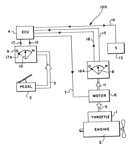
a master control unit (2, 3, 9, 10) for
operation by an operator and for supplying a first
signal (12) indicative of the operator's request for
fueling of the engine;
a slaved actuator unit (6, 5, 1, 11, 8) for
supplying fuel to the engine in accordance with a
command signal (7) and providing a second signal (15)
indicative of the current supply of fuel to the engine;
and
a control unit (4) for receiving at least said
first and second signals and for processing same in
accordance with predetermined logic rules to issue said
command signal, said control unit having at least one
mode of operation ("normal") wherein said command
signals are intended to cause said slaved actuation unit
to supply an amount of fuel to said engine which is a
function of said first signal;
said system characterized by:
means for comparing said first signal to said
second signal to said second signal to determine if the
amount of fuel supplied to said engine remains
substantially different from said function of said first
signal for at least a predetermined period of time.
2. The system of claim 1 further characterized
by means effective to cause said control unit to issue
command signals causing said slaved actuator to assume a
minimum ("idle") fueling condition if, during operation
of said control unit in said one mode of operation, a
comparison of said first and second signals indicates
that the amount of fuel supplied to said engine remains
substantially different from said function of said first
signal for at least said predetermined period of time.
- 12 -
3. The system of claim 2 wherein said slaved
actuator unit is spring biased towards the minimum
fueling position thereof.
4. The system of claim 1 further characterized
by means effective to cause said control unit to
continuously issue command signals causing said slaved
actuator to assume and maintain a minimum ("idle")
fueling condition if, during operation of said control
unit in said one mode of operation, a comparison of said
first and second signals indicates that the amount of
fuel supplied to said engine remains substantially
different from said function of said first signal for at
least said predetermined period of time.
5. The system of claim 4 wherein said slaved
actuator unit is spring biased towards the minimum
fueling position thereof.
6. A fuel control system for controlling the
supply of fuel to an internal combustion engine, said
system comprising;
a master control unit (2, 3, 9, 10) for
operation by an operator and for supplying a first
signal (12) indicative of the operator's request for
fueling of the engine;
a slaved actuator unit (6, 5, 1, 11, 8) for
supplying fuel to the engine in accordance with a
command signal (7) and providing a second signal (15)
indicative of the current supply of fuel to the engine;
and
a control unit (4) for receiving at least said
first and second signals and for processing same in
accordance with predetermined logic rules to issue said
- 13 -
command signal, said control unit having at least one
mode of operation ("normal") wherein said command
signals are intended to cause said slaved actuation unit
to supply an amount of fuel to said engine which is a
function of said first signal,
said system characterized by:
a first two-position switch (17A) associated
with said master control and assuming one of said first
and second positions (on/off, open/closed, 0/1) when
said master control is in a position corresponding to
the operator's desire for minimum ("idle") fueling of
said engine and assuming said other of said first and
second positions thereof when said master control is not
in the position corresponding to the operator's desire
for minimum fueling of said engine, said first switch
providing a third signal (17) indicative of the current
position thereof; and
a second two-position switch (16A) associated
with said slaved actuation unit and assuming said one of
said first and second positions (on/off, open/closed,
0/1) when said slaved actuation unit is not in a
position corresponding to desire for minimum ("idle")
fueling of said engine and assuming said other of said
first and second positions thereof when said slaved
actuation unit is in the position corresponding to
minimum fueling of said engine, said second switch
providing a fourth signal (16) indicative of the current
position thereof.
7. The system of claim 6 further characterized
by means effective to cause said control unit to issue
command signals causing said slaved actuator to assume
said minimum ("idle") fueling condition if, for a
predetermined period of time, said third and fourth
- 14 -
signals indicate that said first and second switches are
both in said first positions or are both in said second
positions thereof.
8. The system of claim 6 further characterized
by means effective to cause said control unit to issue
command signals causing said slaved actuator to assume
and to maintain said minimum ("idle") fueling condition
if, for a predetermined period of time, said third and
fourth signals indicate that said first and second
switches are both in said first positions or are both in
said second positions thereof.
9. A fuel control system for controlling the
supply of fuel to an internal combustion engine, said
system comprising;
a master control unit (2, 3, 9, 10) for
operation by an operator and for supplying a first
signal (12) indicative of the operator's request for
fueling of the engine;
a slaved actuator unit (6, 5, 1, 11, 8) for
supplying fuel to the engine in accordance with a
command signal (7) and providing a second signal (15)
indicative of the current supply of fuel to the engine;
and
a control unit (4) for receiving at least said
first and second signals and for processing same in
accordance with predetermined logic rules to issue said
command signal, said control unit having at least one
mode of operation ("normal") wherein said command
signals are intended to cause said slaved actuation unit
to supply an amount of fuel to said engine which is a
function of said first signal,
said system characterized by:
- 15 -
means for comparing said first signal to a
first reference value (REF-1) corresponding to a maximum
expected value of said first signal and to a second
reference value (REF-2) corresponding to a minimum
expected value of said first signal.
10. The system of claim 9 further
characterized by means for comparing said second signal
to a third reference value (REF-3) corresponding to a
maximum expected value of said second value and to a
fourth reference value (REF-4) corresponding to a
minimum expected value of said second value.
11. The system of claim 10 further
characterized by means effective to cause said control
unit to issue command signals causing said slaved
actuator to assume a minimum ("idle") fueling condition
if said first signal exceeds said first reference, said
second signal exceeds said third reference, said second
reference exceeds said first signal or said fourth
reference exceeds said second signal.
12. A fuel control system for controlling the
supply of fuel to an internal combustion engine, said
system comprising;
a master control unit (2, 3, 9, 10) for
operation by an operator and for supplying a first
signal (12) indicative of the operator's request for
fueling of the engine;
a slaved actuator unit (6, 5, 1, 11, 8) for
supplying fuel to the engine in accordance with a
command signal (7) and providing a second signal (15)
indicative of the current supply of fuel to the engine,
said slaved unit including an electrical motor (6) and
said second signal having a magnitude indicative of the
power drawn by said motor; and
- 16 -
a control unit (4) for receiving at least said
first and second signals and for processing same in
accordance with predetermined logic rules to issue said
command signal, said control unit having at least one
mode of operation ("normal") wherein said command
signals are intended to cause said slaved actuation unit
to supply an amount of fuel to said engine which is a
function of said first signal,
said system characterized by:
means for comparing the magnitude of said
second signal to a power reference value corresponding
to maximum acceptable power drawn of said electrical
motor.
13. The system of claim 12 further
characterized by means effective to cause said control
unit to issue command signals causing said slaved
actuator to assume no more than a substantially minimum
("idle") fueling condition if, said the magnitude of
said second signal exceeds said power reference value.
14. A fuel control system for controlling the
supply of fuel to an internal combustion engine
associated with an at least partially automated
transmission system, said system comprising;
a master control unit (2, 3, 9, 10) for
operation by an operator and for supplying a first
signal (12) indicative of the operator's request for
fueling of the engine;
a slaved actuator unit (6, 5, 1, 11, 8) for
supplying fuel to the engine in accordance with a fuel
command signal (7) and providing a second signal (15)
indicative of the current supply of fuel to the engine;
- 17 -
a transmission shifter (13) for shifting a
change gear transmission in accordance with a shift
command signal (14) and providing a third signal (14)
indicative of current shifter position; and
a control unit (4) for receiving at least said
first, second and third signals and for processing same
in accordance with predetermined logic rules to issue
said fuel and shift command signals, said control unit
having at least one mode of operation ("normal") wherein
said fuel command signals are intended to cause said
slaved actuation unit to supply an amount of fuel to
said engine which is a function of said first signal,
and at least one other mode of operation wherein said
fuel command signals are intended to cause said slaved
actuator to supply an amount to said engine which is
independent of said first signal;
said system characterized by:
means for comparing said first signal to said
second signal to determine if the amount of fuel
supplied to said engine remains substantially different
from said function of said first signal for at least a
predetermined period of time; and
means effective to cause said control unit to
issue command signals causing said slaved actuator to
assume a minimum ("idle") fueling condition and for
prohibiting said controller issuing shift command
signals effective to initiate a ratio change if, during
operation of said control unit in said one mode of
operation, a comparison of said first and second signals
indicates that the amount of fuel supplied to said
engine remains substantially different from said
function of said first signal for at least a
predetermined period of time.
- 18 -
15. The system of claim 14 wherein said slaved
actuator unit is spring biased towards the minimum
fueling position thereof.
16. A fuel control system for controlling the
supply of fuel to an internal combustion engine
associated with an at least partially automated
transmission system, said system comprising;
a master control unit (2, 3, 9, 10) for
operation by an operator and for supplying a first
signal (12) indicative of the operator's request for
fueling of the engine;
a slaved actuator unit (6, 5, 1, 11, 8) for
supplying fuel to the engine in accordance with a fuel
command signal (7) and providing a second signal (15)
indicative of the current supply of fuel to the engine;
a transmission shifter (13) for shifting a
change gear transmission in accordance with a shift
command signal (14) and providing a third signal (14)
indicative of current shifter position; and
a control unit (4) for receiving at least said
first, second and third signals and for processing same
in accordance with predetermined logic rules to issue
said fuel and shift command signals, said control unit
having at least one mode of operation ("normal") wherein
said fuel command signals are intended to cause said
slaved actuation unit to supply an amount of fuel to
said engine which is a function of said first signal,
and at least one other mode of operation wherein said
fuel command signals are intended to cause said slaved
actuator to supply an amount to said engine which is
independent of said first signal;
said system characterized by:
- 19 -
a first two-position switch (17A) associated
with said master control and assuming one of said first
and second positions (on/off, open/closed, 0/1) when
said master control is in a position corresponding to
the operator's desire for minimum ("idle") fueling of
said engine and assuming said other of said first and
second positions thereof when said master control is not
in the position corresponding to the operator's desire
for minimum fueling of said engine, said first switch
providing a third signal (17) indicative of the current
position thereof,
a second two-position switch (16A) associated
with said slaved actuation unit and assuming said one of
said first and second positions (on/off, open/closed,
0/1) when said slaved actuation unit is not in a
position corresponding to desire for minimum ("idle")
fueling of said engine and assuming said other of said
first and second positions thereof when said slaved
actuation unit is in the position corresponding to
minimum fueling of said engine, said second switch
providing a fourth signal (16) indicative of the current
position thereof; and
means effective to cause said control unit to
issue command signals causing said slaved actuator to
assume said minimum ("idle") fueling condition and said
shifter to retain the transmission in the currently
engaged ratio if said third and fourth signals indicate
that said first and second switches are both in said
first positions or are both in said second positions
thereof for at least a predetermined period of time.
17. A fuel control system for controlling the
supply of fuel to an internal combustion engine
associated with an at least partially automated
transmission system, said system comprising;
- 20 -
a master control unit (2, 3, 9, 10) for
operation by an operator and for supplying a first
signal (12) indicative of the operator's request for
fueling of the engine;
a slaved actuator unit (6, 5, 1, 11, 8) for
supplying fuel to the engine in accordance with a fuel
command signal (7) and providing a second signal (15)
indicative of the current supply of fuel to the engine;
a transmission shifter (13) for shifting a
change gear transmission in accordance with a shift
command signal (14) and for providing a third signal
(14) indicative of current shifter condition; and
a control unit (4) for receiving at least said
first, second and third signals and for processing same
in accordance with predetermined logic rules to issue
said fuel and shift command signals, said control unit
having at least one mode of operation ("normal") wherein
said fuel command signals are intended to cause said
slaved actuation unit to supply an amount of fuel to
said engine which is a function of said first signal,
and at least one other mode of operation wherein said
fuel command signals are intended to cause said slaved
actuator to supply an amount to said engine which is
independent of said first signal;
said system characterized by:
means for comparing said first signal to a
first reference value (REF-1) corresponding to a maximum
expected value of said first signal and to a second
reference value (REF-2) corresponding to a minimum
expected value of said first signal;
means for comparing said second signal to a
third reference value (REF-3) corresponding to a maximum
expected value of said second value and to a fourth
reference value (REF-4) corresponding to a minimum
expected value of said second value; and
- 21 -
means effective to cause said control unit to
issue command signals causing said shifter to retain
said transmission in the currently engaged ratio and
said slaved actuator to assume a minimum ("idle")
fueling condition if said first signal exceeds said
first reference, said second signal exceeds said third
reference, said second reference exceeds said first
signal or said fourth reference exceeds said fourth
reference exceeds said second signal.
18. A fuel control system for controlling the
supply of fuel to an internal combustion engine
associated with an at least partially automated
transmission system, said system comprising;
a master control unit (2, 3, 9, 10) for
operation by an operator and for supplying a first
signal (12) indicative of the operator's request for
fueling of the engine;
said slaved unit including an electrical motor
(6) and said second signal having a magnitude indicative
of the power drawn by said motor; and
a transmission shifter (13) for shifting a
change gear transmission in accordance with a shift
command signal (14) and for providing a third signal
(14) indicative of current shifter position; and
a control unit (4) for receiving at least said
first, second and third signals and for processing same
in accordance with predetermined logic rules to issue
said fuel and shift command signals, said control unit
having at least one mode of operation ("normal") wherein
said fuel command signals are intended to cause said
slaved actuation unit to supply an amount of fuel to
said engine which is a function of said first signal,
and at least one other mode of operation wherein said
- 22 -
fuel command signals are intended to cause said slaved
actuator to supply an amount to said engine which is
independent of said first signal;
said system characterized by:
means for comparing the magnitude of said
second signal to a power reference value corresponding
to maximum acceptable power draw of said electrical
motor; and
means effective to cause said control unit to
issue command signals causing said shifter to retain
said transmission in the currently engaged ratio and
said slaved actuator to assume no more than a
substantially minimum ("idle") fueling condition if said
the magnitude of said second signal exceeds said power
reference value.
19. A fault detection method for a fuel control
system for controlling the supply of fuel to an internal
combustion engine, said system comprising;
a master control unit (2, 3, 9, 10) for
operation by an operator and for supplying a first
signal (12) indicative of the operator's request for
fueling of the engine;
a slaved actuator unit (6, 5, 1, 11, 8) for
supplying fuel to the engine in accordance with a
command signal (7) and providing a second signal (15)
indicative of the current supply of fuel to the engine;
and
a control unit (4) for receiving at least said
first and second signals and for processing same in
accordance with predetermined logic rules to issue said
command signal, said control unit having at least one
mode of operation ("normal") wherein said command
signals are intended to cause said slaved actuation unit
to supply an amount of fuel to said engine which is a
function of said first signal;
- 23 -
said method characterized by:
comparing said first signal to said second
signal to said second signal to determine if the amount
of fuel supplied to said engine remains substantially
different from said function of said first signal for at
least a predetermined period of time; and
causing said control unit to issue command
signals causing said slaved actuator to assume and
maintain a minimum ("idle") fueling condition if, during
operation of said control unit in said one mode of
operation, comparing of said first and second signals
indicates that the amount of fuel supplied to said
engine remains substantially different from said
function of said first signal for at least said
predetermined period of time.
20. A fault detection method for a fuel control
system for controlling the supply of fuel to an internal
combustion engine, said system comprising;
a master control unit (2, 3, 9, 10) for
operation by an operator and for supplying a first
signal (12) indicative of the operator's request for
fueling of the engine;
a slaved actuator unit (6, 5, 1, 11, 8) for
supplying fuel to the engine in accordance with a
command signal (7) and providing a second signal (15)
indicative of the current supply of fuel to the engine;
and
a control unit (4) for receiving at least said
first and second signals and for processing same in
accordance with predetermined logic rules to issue said
command signal, said control unit having at least one
mode of operation ("normal") wherein said command
signals are intended to cause said slaved actuation unit
to supply an amount of fuel to said engine which is a
function of said first signal,
- 24 -
said method characterized by:
providing a first two-position switch (17A)
associated with said master control and assuming one of
said first and second positions (on/off, open/closed,
0/1) when said master control is in a position
corresponding to the operator's desire for minimum
("idle") fueling of said engine and assuming said other
of said first and second positions thereof when said
master control is not in the position corresponding to
the operator's desire for minimum fueling of said
engine, said first switch providing a third signal (17)
indicative of the current position thereof;
providing a second two-position switch (16A)
associated with said slaved actuation unit and assuming
said one of said first and second positions (on/off,
open/closed, 0/1) when said slaved actuation unit is not
in a position corresponding to desire for minimum
("idle") fueling of said engine and assuming said other
of said first and second positions thereof when said
slaved actuation unit is in the position corresponding
to minimum fueling of said engine, said second switch
providing a fourth signal (16) indicative of the current
position thereof; and
causing said control unit to issue command
signals causing said slaved actuator to assume and
maintain said minimum ("idle") fueling condition if, for
a predetermined period of time, said third and fourth
signals indicate that said first and second switches are
both in said first positions or are both in said second
positions thereof.
21. A fault detection method for a fuel control
system for controlling the supply of fuel to an internal
combustion engine, said system comprising;
- 25 -
a master control unit (2, 3, 9, 10) for
operation by an operator and for supplying a first
signal (12) indicative of the operator's request for
fueling of the engine;
a slaved actuator unit (6, 5, 1, 11, 8) for
supplying fuel to the engine in accordance with a
command signal (7) and providing a second signal (15)
indicative of the current supply of fuel to the engine;
and
a control unit (4) for receiving at least said
first and second signals and for processing same in
accordance with predetermined logic rules to issue said
command signal, said control unit having at least one
mode of operation ("normal") wherein said command
signals are intended to cause said slaved actuation unit
to supply an amount of fuel to said engine which is a
function of said first signal,
said method characterized by:
comparing said first signal to a first
reference value (REF-1) corresponding to a maximum
expected value of said first signal and to a second
reference value (REF-2) corresponding to a minimum
expected value of said first signal;
said second signal to a third reference value
(REF-3) corresponding to a maximum expected value of
said second value and to a fourth reference value
(REF-4) corresponding to a minimum expected value of
said second value; and
causing said control unit to issue command
signals causing said slaved actuator to assume and
maintain a minimum ("idle") fueling condition if said
first signal exceeds said first reference, said second
signal exceeds said third reference, said second
reference exceeds said first signal or said fourth
reference exceeds said second signal.
- 26 -
22. A fault detection method for a fuel control
system for controlling the supply of fuel to an internal
combustion engine associated with an at least partially
automated transmission system, said system comprising;
a master control unit (2, 3, 9, 10) for
operation by an operator and for supplying a first
signal (12) indicative of the operator's request for
fueling of the engine;
a slaved actuator unit (6, 5, 1, 11, 8) for
supplying fuel to the engine in accordance with a fuel
command signal (7) and providing a second signal (15)
indicative of the current supply of fuel to the engine;
a transmission shifter (13) for shifting a
change gear transmission in accordance with a shift
command signal (14) and providing a third signal (14)
indicative of current shifter position; and
a control unit (4) for receiving at least said
first, second and third signals and for processing same
in accordance with predetermined logic rules to issue
said fuel and shift command signals, said control unit
having at least one mode of operation ("normal") wherein
said fuel command signals are intended to cause said
slaved actuation unit to supply an amount of fuel to
said engine which is a function of said first signal,
and at least one other mode of operation wherein said
fuel command signals are intended to cause said slaved
actuator to supply an amount to said engine which is
independent of said first signal;
said method characterized by:
comparing said first signal to said second
signal to determine if the amount of fuel supplied to
said engine remains substantially different from said
function of said first signal for at least a
predetermined period of time; and
- 27 -
causing said control unit to issue command
signals causing said slaved actuator to assume a minimum
("idle") fueling condition and for prohibiting said
controller issuing shift command signals effective to
initiate a ratio change if, during operation of said
control unit in said one mode of operation, a comparison
of said first and second signals indicates that the
amount of fuel supplied to said engine remains
substantially different from said function of said first
signal for at least a predetermined period of time.
23. A fault detection method for a fuel control
system for controlling the supply of fuel to an internal
combustion engine associated with an at least partially
automated transmission system, said system comprising;
a master control unit (2, 3, 9, 10) for
operation by an operator and for supplying a first
signal (12) indicative of the operator's request for
fueling of the engine;
a slaved actuator unit (6, 5, 1, 11, 8) for
supplying fuel to the engine in accordance with a fuel
command signal (7) and providing a second signal (15)
indicative of the current supply of fuel to the engine;
a transmission shifter (13) for shifting a
change gear transmission in accordance with a shift
command signal (14) and providing a third signal (14)
indicative of current shifter position; and
a control unit (4) for receiving at least said
first, second and third signals and for processing same
in accordance with predetermined logic rules to issue
said fuel and shift command signals, said control unit
having at least one mode of operation ("normal") wherein
said fuel command signals are intended to cause said
slaved actuation unit to supply an amount of fuel to
- 28 -
said engine which is a function of said first signal,
and at least one other mode of operation wherein said
fuel command signals are intended to cause said slaved
actuator to supply an amount to said engine which is
independent of said first signal;
said method characterized by:
providing a first two-position switch (17A)
associated with said master control and assuming one of
said first and second positions (on/off, open/closed,
0/1) when said master control is in a position
corresponding to the operator's desire for minimum
("idle") fueling of said engine and assuming said other
of said first and second positions thereof when said
master control is not in the position corresponding to
the operator's desire for minimum fueling of said
engine, said first switch providing a third signal (17)
indicative of the current position thereof,
providing a second two-position switch (16A)
associated with said slaved actuation unit and assuming
said one of said first and second positions (on/off,
open/closed, 0/1) when said slaved actuation unit is not
in a position corresponding to desire for minimum
("idle") fueling of said engine and assuming said other
of said first and second positions thereof when said
slaved actuation unit is in the position corresponding
to minimum fueling of said engine, said second switch
providing a fourth signal (16) indicative of the current
position thereof; and
causing said control unit to issue command
signals causing said slaved actuator to assume said
minimum ("idle") fueling condition and said shifter to
retain the transmission in the currently engaged ratio
of third and fourth signals indicate that said first and
second switches are both in said first positions or are
both in said second positions thereof for at least a
predetermined period of time.