Note: Descriptions are shown in the official language in which they were submitted.
COMPOSITE FUEL TANK 2 0 3 ~ 5 5 3
BACKGROUND OF THE INVENTION
1. Technical Field
This invention relates to fuel tanks and, more
particularly, to fuel tanks made of plastic material.
2. Discussion
The desire for a fuel efficient and durable vehicle
that satisfies the requirements of today's sophisticated
consumer has placed difficult demands on modern fuel tank
design. Plastic fuel tanks are gaining notoriety for meeting
these demands. One such demand is the desire to reduce
overall vehicle mass. The use of a lightweight plastic fuel
tank, rather than a conventional metal fuel tank, helps
achieve the goal of reduced vehicle mass.
Another demand on today's vehicle design is
roominess in the passenger compartment. Increasing the
roominess of the passenger compartment, without increasing the
overall size of the vehicle, results in a cramped engine
compartment and under carriage. This cramping of the under
carriage conflicts with the consumer's desire to have a larger
gas tank and thereby have longer range between fill-ups. To
accommodate an optimal design of maximum tank volume in a
minimum of available under carriage space, the fuel tank
design required for a given vehicle may be one of irregular
shape. Conventional metal gas tanks, generally being produced
by a stamping operation, typically cannot easily meet these
irregular shape requirements.
X-
203~553
Another common characteristic of a cramped under
carriage is the gas tank being in close proximity to an
exhaust system. Conventional metal gas tank walls do not
provide insulation from these types of local heat sources.
Safety and crash worthiness is also an important
factor in the design of modern vehicles. Conventional metal
gas tanks usually consist of two diametrically opposed stamped
shells that attach to one another. This attachment results in
a seam that extends around the circumference of the gas tank.
A second seam may also be created where a filler neck attaches
to the gas tank wall. These seams are potential sources of
failure.
Plastic fuel tanks are known in the patent
literature as, for example, in U.S. Patent Nos. 4,660,738 to
Ives; 4,625,980 to Lyzohub; 4,602,722 to Ives; 4,518,091 to
Scheurenbrand et. al.; 4,482,075 to Stotz et. al.; 4,453,564
to Bergesio; 4,416,303 to Scheurenbrand; 3,595,422 to Durrett,
Jr.; 3,552,599 to Redding; and 3,470,907 to Shockey. However,
while each of these designs may have purported advantages over
their metal counterparts, substantial improvements to the art
remain to be made.
Pursuant to the present disclosure a molded one
piece plastic fuel tank is provided with a hollow interior
liner having generally thin airtight walls. The exterior of
the liner is covered by resin impregnated fibrous material.
The liner advantageously serves the purposes of defining the
hollow interior of the tank during molding, protecting the
plastic shell from corrosive fuels, as well as providing a
2039553
secondary fuel containment means for enhanced occupant safety
in the event of impact.
The method for producing this fuel tank preferably
utilizes a resin transfer molding technique where resin is
injected into fibrous reinforcement material. During this
process, fibrous material is placed on a thin-walled liner
that generally conforms to the interior shape of the mold.
the liner is then placed into the mold and serves as a support
for the fibrous material that covers it. As resin is injected
into the mold, the fibrous material between the exterior
surface of the liner and the interior surface of the mold is
impregnated. The liner supports this impregnated material
thereby defining a hollow tank interior. Since the liner can
be made of a material resistant to fuel corrosion the liner,
which remains after the resin has cured, acts as a protective
interior surface for the resin tank walls, if needed. In
addition, the liner can serve as a type of flexible bag or
pouch that may continue to contain fuel, even if the outer
shell is damage.
In accordance with a feature of this disclosure, the
fibrous material is also arranged to provide an integral
filler neck that avoids the need for a connection seam at the
top surface of the tank. Elimination of this seam, along with
the elimination of a circumferential seam inherent in
conventional two piece metal gas tanks, provides further
enhanced structural integrity for the tank.
In the preferred embodiment, the fibrous material is
also arranged in layers at desired locations to allow for the
~ ;
203~553
-
placement of insulative material between the layers. When
resin is subsequently injected into the mold and the layers of
fibrous material are impregnated, the insulative material is
sandwiched between the fibrous layers with the tank wall.
This insulative material serves to insulate selected areas of
the tank from disfavorable exterior environments. In the
preferred embodiment, the insulative material shields the
interior of the tank from heat generated by the exhaust
system.
Embodiments of the invention will now be described with
reference to the accompanying drawings wherein:
Fig. 1 is a cross sectional view illustrating a
molded tank in accordance with an embodiment of the present
invention;
Fig. 2 is a partial cross sectional view of the tank
wall near the exhaust system, along area "2" in Fig. 1,
illustrating the insulative material disposed between layers
of fibrous material;
Fig 3. is a flowchart describing the steps involved
in the preferred method for molding the fuel tank;
Fig. 4 is an exploded, perspective view of an
insulative material being placed between layers of fibrous
material and subsequently being placed on the liner; and
Fig. 5 is a cross sectional view of the mold
illustrating the resin being injected into the fibrous
material which is supported by the liner.
203~553
DESCRIPTION OF THE PREFERRED EMBODIMENTS
It should be understood from the outset that while
this invention will be described in connection with a
particular example, that the scope of the invention need not
be so limited since those skilled in the art will appreciate
that its teachings can be used in a much wider variety of
applications involving automotive fuel tanks and other
applications where the containment of a material is desired.
With this caveat in mind the present invention will be
described in connection with molding a one piece plastic fuel
tank 10.
Figure 1 illustrates a cross-section of the
preferred embodiment for this tank 10. The tank 10
incorporates an interior liner 12, and an insulative material
14 that is disposed completely within a tank wall 16. The
tank 10 also incorporates a conduit 18 defining a passage
leading from an interior portion 20 of the tank 10 to a
location away from the upper surface of the tank thereby
providing a filler neck for the tank. The end of the filler
neck conduit can be covered, if desired, by a more
conventional metallic insert 22 for receiving a typical fuel
tank threaded cap (not shown).
Fig. 1 also illustrates the construction of the tank
wall 16. Generally, the wall 16 is defined by the interior
liner 12 and a resin impregnated fibrous material 24. The
impregnated fibrous material 24 forms the bulk of the tank
wall 16, while the liner 12 covers the interior surface of the
impregnated fibrous material 24. The tank wall 16 near an
,rf ~
2039553
exhaust system 26 includes the interior liner 12 and
impregnated fibrous material 24, as well as the insulative
material 14. The insulative material 14 can be made of a
phenolic foam, mineral batting material or other suitable
material. Insulative material 14 is completely disposed
within the tank wall 16 between inner and outer layers, 24a
and 24b, of impregnated fibrous material. The insulative
material 14 acts as a heat shield, as it insulates the
interior 20 of the tank 10 from heat generated by the exhaust
system 26.
Fig. 2 is an expanded view of the tank wall 16 near
the exhaust system 26. Here, the layered construction of the
tank wall 16 is clearly evident. Starting from the tank
interior 20, the layered construction is shown as follows:
the most interior layer is the liner 12; the next layer is
resin impregnated fibrous material 24a; then the layer of
insulative material 14; and finally another layer 24b of resin
impregnated fibrous material. This final layer of impregnated
fibrous material 24b defines the exterior tank surface 28.
Also shown in Fig 2. is the exhaust system 26 in close
proximity to this exterior tank surface 28.
Fig. 1 also depicts a conduit 18 leading from the
tank interior 20. The metallic filler neck insert 22 can be
attached to the distal end of the conduit 18. Since the
conduit 18 is incorporated into the one piece design of the
tank 10, there is no seam at the tank wall 16. Rather, the
conduit 18 extends from the tank 10 as a continuous extension
of the tank wall 16. Therefore, a seam where a filler neck
, .
2039553
would normally attach to the tank wall is avoided, and the
structural integrity of the tank is enhanced.
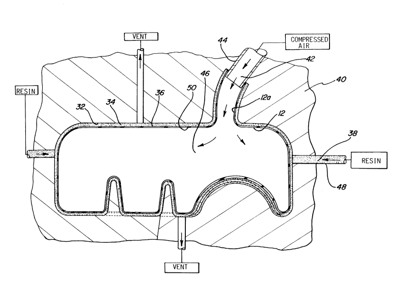
Fig. 3 is a flowchart that depicts the preferred
steps involved in the process of molding the one piece plastic
fuel tank 10. The first step is to create the interior liner
12. This liner 12 should generally be thin walled, airtight,
fuel impervious and conform to an interior mold surface 32 as
shown in Fig. 5. In the preferred embodiment, the liner 12 is
made from a corrosion resistant material 30 such as
polyethylene or polypropylene. This material 30 is
impermeable and able to withstand prolonged exposure to methyl
and ethyl alcohol, and gasoline blends which could otherwise
degrade the plastic tank wall 16 depending on the type of
resin system employed. As will be seen, the liner 12 is
required to be airtight since compressed air is pumped into
the liner 12 during the molding process. The liner 12 can be
made in many ways such as blow molding, rotational molding or
twin sheet thermoforming. The next step on the flowchart is
to attach fibrous material preforms 34 to the liner 12. The
preforms consist of irregularly shaped shells of multiple
fibers which are generally held in shape by a suitable binder.
The preforms are preferably made by a process described in
commonly assigned U.S. Serial No. 2872-00188, filed April 24,
1990, entitled "Method and Apparatus For Forming Fiber
Reinforced Plastic Preforms From a Wet Slurry" by Freeman et
al which is hereby incorporated by reference. Attaching these
preforms involves suitably adhering the fibrous material
preforms 34 on the exterior liner surface 36. Note, when the
2039553
fibrous preforms 34 are placed on the exterior liner surface
36, the fibers may be selectively oriented to achieve maximum
structural integrity.
In the preferred embodiment, the liner 12 has a
tubular extension 12a that extends outwardly from the exterior
surface 36 of the liner 12. This tubular extension 12a
corresponds to the location of the conduit 18 leading from the
tank interior 20. The fibrous material preforms 34 may
themselves include extensions which conform to lever extension
12a or additional fibrous material may be wrapped around the
tubular extension 12a of the liner 12. When this fibrous
material is subsequently impregnated, the conduit 18 leading
from the tank interior 20 is formed.
As discussed previously, insulative material 14 may
be placed between layers of the fibrous material. As shown in
Fig. 4, this process comprises layering the fibrous material
preforms 34a and 34b on the liner 12, and placing insulative
material 14 between these layers of fibrous material. When
the fibrous material is impregnated, the insulative material
14 is completely surrounded and disposed within the
impregnated fibrous material 24.
The next step in the process is to load the covered
liner assembly into the mold 40. This entails placing the
liner 12, covered with fibrous material, into the mold 40 and
closing the mold 40. The covered liner 12 should
substantially conform to the shape of the interior mold
surface 32. Thus, the fibrous material 34 is supported by
2039553
liner 12 in the gap between the exterior liner surface 36 and
the interior mold surface 32.
The next step is to apply compressed air 42 to the
liner 12. A source of compressed air 42 is connected to the
conduit 18 via a suitable conduit 44 extending through the
mold 40. By applying compressed air 42 to the interior liner
cavity 46, via the conduit 18, the liner 12 becomes difficult
to collapse. This allows the liner 12 to maintain its shape,
and prevents the liner 12 from collapsing, when the resin 38
is injected.
The next step in the molding process is to inject a
suitable resin 38 such as an epoxy or phenolic resin into the
mold 40 as shown in Fig. 5. The resin 38 is injected into the
mold 40 via a suitable conduit 48. This resin 38 impregnates
the fibrous material that lies between the exterior liner
surface 36 and interior mold surface 32. As the resin 38 is
injected and impregnates the fibrous material, the compressed
air 42 supports the liner 12 and keeps it from collapsing.
While the resin 38 cures, the liner 12 also supports the resin
impregnated material 24 and defines the interior tank surface
50.
The next step in the molding process is to open the
mold 40 and remove the tank 10 after the resin 38 has cured.
Once the resin 38 has cured, the completed tank 10 is removed
from the mold 40 and the compressed air source is disconnected
from the conduit 18. A metallic filler neck insert 22 may
then be attached to the tank 10 immediately or during the
assembly of the vehicle. Alternatively, the metal insert
20~9~53
-
could be molded in place during the above-described molding
process.
As discussed previously, the liner 12 remains in the
tank 10 and acts as a protective surface for the tank walls
made of the cured resin impregnated fibrous material 24 since
the liner 12 is made of a corrosion resistant material. Liner
12 also serves as a "back-up" or secondary container for the
fuel which would tend to continue to hold fuel even if the
outer plastic shell should become damaged.
It should be understood that various modifications
of the preferred embodiments will become apparent to those
skilled in the art after a study of the specification,
drawings, and following claims.