Language selection

Search

Patent 2039574 Summary

Third-party information liability

Some of the information on this Web page has been provided by external sources. The Government of Canada is not responsible for the accuracy, reliability or currency of the information supplied by external sources. Users wishing to rely upon this information should consult directly with the source of the information. Content provided by external sources is not subject to official languages, privacy and accessibility requirements.

Claims and Abstract availability

Any discrepancies in the text and image of the Claims and Abstract are due to differing posting times. Text of the Claims and Abstract are posted:

  • At the time the application is open to public inspection;
  • At the time of issue of the patent (grant).
(12) Patent Application: (11) CA 2039574
(54) English Title: BATTERY TERMINAL CLAMP
(54) French Title: COSSE DE BATTERIE
Status: Deemed Abandoned and Beyond the Period of Reinstatement - Pending Response to Notice of Disregarded Communication
Bibliographic Data
(51) International Patent Classification (IPC):
  • H01R 11/24 (2006.01)
  • H01R 11/28 (2006.01)
(72) Inventors :
  • LEE, KUO-SHU (Taiwan, Province of China)
  • LEE, KUO-SHU (Taiwan, Province of China)
(73) Owners :
  • KUO-SHU LEE
  • KUO-SHU LEE
(71) Applicants :
(74) Agent: SMART & BIGGAR LP
(74) Associate agent:
(45) Issued:
(22) Filed Date: 1991-04-02
(41) Open to Public Inspection: 1992-06-22
Examination requested: 1992-07-02
Availability of licence: N/A
Dedicated to the Public: N/A
(25) Language of filing: English

Patent Cooperation Treaty (PCT): No

(30) Application Priority Data:
Application No. Country/Territory Date
631,645 (United States of America) 1990-12-21

Abstracts

English Abstract


BATTERY TERMINAL CLAMP
ABSTRACT
A battery terminal clamp of the type
comprising a conductive sliding clip movably secured to
a terminal clamp at one side by a screw for clamping on
a side mounted battery terminal of a car battery. The
conductive sliding clip is stopped from moving backward
by a side projection made on the terminal clamp when it
is pushed out to a clamping position. Two opposite
side edges are bent inwards through 90° angle to firmly
attach to the two opposite side walls of the terminal
clamp so as to protect the conductive sliding clip
against torsional force.


Claims

Note: Claims are shown in the official language in which they were submitted.

CLAIMS
1. A battery terminal clamp of the type
comprising a conductive sliding clip movably secured to
a terminal clamp at one side by a screw, wherein said
conductive sliding clip has an opening at the front end
thereof for retaining a battery terminal, an elongated
sliding slot longitudinally disposed at a lower end
through which said screw is inserted to secure said
sliding clip to said terminal clamp, and two opposite
edges at two opposite sides respectively bent downward
through 90° angle to retain said terminal clamp at two
opposite sides and protect said sliding clip against
torsional force, and wherein said sliding clip can be
pushed out to protrude beyond the top edge of said
terminal clamp and stopped, at a clamping position for
clamping on a battery terminal, by a side projection
made on said terminal clamp at one side.
2. The battery terminal clamp of claim 1,
wherein said sliding clip further comprises two
opposite, hooked portions at the front end thereof.

3. The battery terminal clamp of claim 1,
wherein said elongated sliding slot can be a closed hole
or an elongated hole having an one communicating with
said opening.

Description

Note: Descriptions are shown in the official language in which they were submitted.


6~ L~
BATTERY TERMINAL CLAMP
BACKGROUND OF T~IE INVENTION
The present invention relates to U.S. Pat. Nos. 4,923,415
and 4,975,089. In the present speci~ication, there is
disclosed a battery terminal elamp which has a sliding clip
movably secured at one side of a conventional terminal clamp
and retained in a working position by a screw for clamping on
a side mounted battery terminal.
Battery failure has been known as one of the most common
reasons which cause a motor vehicle to be unable to start. In
such an emergency, jumper eables are eommonly used to connect
the car battery in trouble to the car battery of another car.
A jumper cable is generally comprised of two battery terminal
clamps connected through a cable. However, com~entional
battery terminal clamps are not suitable for use to clamp on
a side mounted battery terminal when the battery is set in the
engine compartment of a motor vehicle.
SUMM~RY OF THE INVENTION
The present invention eliminates the aforesaid problem.
According to the present invention, there is provided a
battery terminal clamp having a sliding clip movably secured
in a conventional terminal clamp at one side, which slidin~
clip can be moved back in a received position or pushed out
and then fixed by a screw at a clamping position for clamping
on the side mounted terminal of a car battery.

The present invention also provides a battery terminal
clamp of-the type comprising a conductive sliding clip movably
secured to a terminal clamp at one side by a screw, wherein
the conductive sliding clip has an opening at the front end
thereof for retaining a battery terminal, an elongated sliding
slot longitudinally disposed at a lower end through which the
screw is inserted to secure the sliding clip to the terminal
clamp, and two opposite edges at two opposite sides
respectively bent downward through 90 angle to retain the
terminal clamp at two opposite sides and protect the sliding
clip against torsional force, and wherein the sllding clip can
be pushed out to protrude be~ond the top edge of the terminal
clamp and stopped, at a clamping position for clamping on a
battery terminal, by a side projection made on the terminal
clamp at one side.
BRIEF DESCRIPTION OF THE DRAWINGS
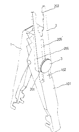
Fig. 1 illustrates a battery terminal clamp embodying the
present invention wherein the sliding clip is disposed at a
received position;
Fig. 2 illustrates the embodiment of Fig.1 wherein the
sliding clip is pushed into a clamping position;
Fig. 3 illustrates an alternate form of the present
invention wherein the sliding clip is disposed at a received
position;
Fig. 4 illustrates the embodiment of Fig. 3 wherein the
sliding clip is pushed into a clamping position;

~ ~ 3 ~
Fig. 5 is a side view of the present
invention wherein the sliding clip is pushed into a
clamping position; and
Fig. 6 is another side view of the present
invention wherein the sliding clip is disposed at a
received position.
DETAILED DESCRIPTION OF THE PREFERRED EMBODIMENTS
Referring to Figs. 1 through 4, the present
invention is generally comprised of a conventional
terminal clamp 1, and a sliding clip 2 secured to said
terminal clamp 1 at one side by a screw 3.
As illustrated, the sliding clip 2 is secured
to the clamping element 101 of the terminal clamp 1 at
the outer side by the screw 3. ~oosening the screw 3
permits the sliding clip 2 to be pushed to project over
the top edge of the terminal clamp l into a clamping
position. The clamping element 101 has a side
projection 102 for stopping the bottom edge 20] of the
sliding clip 2 when the sliding clip 2 is moved into a
clamping position, so as to stop the sliding clip 2 from
moving backward (see Fig. 5). As soon as the sliding

clip 2 is moved into a clarnping position, the screw 3 is
fastened up again to fixedlv secure the sliding clip 2
in position. When not in use, the sliding clip 2 can
be moved back to closely attach to the clamping element
101 and fi~edly secured thereto by the screw 3 (see Fig.
6).
Referring to Figs. 1 and 2 again, the sliding
clip 2 has an opening 203 at the front end thereof ~or
retaining a battery terminal, a closed, elongated
sliding slot 205 longitudinally disposed at a lower end
through which the screw 3 is inserted to secure the
sliding clip 2 to the clamping element 101 o~ the
terminal clamp 1 permitting the sliding clip 2 to slide
in longitudinal direction on the clamping element 101,
1~ and two opposite edges 206 at two opposite sides which
are bent downward through 90 angle for retaining -the
two opposite side walls of the clamping element 101.
sv means of the effect of the two opposite edges 206,
the sliding clip 2 is permitted to slide in longitudinal
direction on the clamping element 101 and protected
against torsional force.

Referr1ng to Figs. 3 and 4, there IS
illustrated an alternate form of the sliding clip 2.
In this embodiment, the sliding cli.p 2 has an opening
203 at the front end thereof for retaining a battery
terminal, an elongated sliding slot 207 extending
downward from said opening 203, and two opposite hooked
portions 20~ bilaterally disposed at the front end
thereof. When the sliding clip 2 is moved back into
a received position, t-he two opposite hooked portions
204 are respectively engaged in the ront end of the
clamping element 101 so that the sliding clip 2 will not
drop from the clamping element 101 after it is secured
in position by a screw 3. Similar to the aforesaid
first embodiment, the two opposite sides of the sliding
clip 2 are respectively bent downward through 90 angle
to firmly retain the two opposite side walls of the
clamping element 101 against torsional force.

Representative Drawing
A single figure which represents the drawing illustrating the invention.
Administrative Status

2024-08-01:As part of the Next Generation Patents (NGP) transition, the Canadian Patents Database (CPD) now contains a more detailed Event History, which replicates the Event Log of our new back-office solution.

Please note that "Inactive:" events refers to events no longer in use in our new back-office solution.

For a clearer understanding of the status of the application/patent presented on this page, the site Disclaimer , as well as the definitions for Patent , Event History , Maintenance Fee  and Payment History  should be consulted.

Event History

Description Date
Inactive: IPC from MCD 2006-03-11
Time Limit for Reversal Expired 1994-10-03
Application Not Reinstated by Deadline 1994-10-03
Inactive: Adhoc Request Documented 1994-04-04
Deemed Abandoned - Failure to Respond to Maintenance Fee Notice 1994-04-04
Request for Examination Requirements Determined Compliant 1992-07-02
All Requirements for Examination Determined Compliant 1992-07-02
Application Published (Open to Public Inspection) 1992-06-22

Abandonment History

Abandonment Date Reason Reinstatement Date
1994-04-04
Owners on Record

Note: Records showing the ownership history in alphabetical order.

Current Owners on Record
KUO-SHU LEE
KUO-SHU LEE
Past Owners on Record
None
Past Owners that do not appear in the "Owners on Record" listing will appear in other documentation within the application.
Documents

To view selected files, please enter reCAPTCHA code :


To view images, click a link in the Document Description column. To download the documents, select one or more checkboxes in the first column and then click the "Download Selected in PDF format (Zip Archive)" or the "Download Selected as Single PDF" button.

List of published and non-published patent-specific documents on the CPD .

If you have any difficulty accessing content, you can call the Client Service Centre at 1-866-997-1936 or send them an e-mail at CIPO Client Service Centre.


Document
Description 
Date
(yyyy-mm-dd) 
Number of pages   Size of Image (KB) 
Cover Page 1992-06-22 1 14
Drawings 1992-06-22 6 67
Claims 1992-06-22 2 30
Abstract 1992-06-22 1 15
Descriptions 1992-06-22 5 131
Representative drawing 1999-07-07 1 11
Fees 1993-03-03 1 27
Fees 1993-03-03 1 24