Sélection de la langue

Search

Sommaire du brevet 2039574 

Énoncé de désistement de responsabilité concernant l'information provenant de tiers

Une partie des informations de ce site Web a été fournie par des sources externes. Le gouvernement du Canada n'assume aucune responsabilité concernant la précision, l'actualité ou la fiabilité des informations fournies par les sources externes. Les utilisateurs qui désirent employer cette information devraient consulter directement la source des informations. Le contenu fourni par les sources externes n'est pas assujetti aux exigences sur les langues officielles, la protection des renseignements personnels et l'accessibilité.

Disponibilité de l'Abrégé et des Revendications

L'apparition de différences dans le texte et l'image des Revendications et de l'Abrégé dépend du moment auquel le document est publié. Les textes des Revendications et de l'Abrégé sont affichés :

  • lorsque la demande peut être examinée par le public;
  • lorsque le brevet est émis (délivrance).
(12) Demande de brevet: (11) CA 2039574
(54) Titre français: COSSE DE BATTERIE
(54) Titre anglais: BATTERY TERMINAL CLAMP
Statut: Réputée abandonnée et au-delà du délai pour le rétablissement - en attente de la réponse à l’avis de communication rejetée
Données bibliographiques
(51) Classification internationale des brevets (CIB):
  • H01R 11/24 (2006.01)
  • H01R 11/28 (2006.01)
(72) Inventeurs :
  • LEE, KUO-SHU (Taïwan, Province de Chine)
  • LEE, KUO-SHU (Taïwan, Province de Chine)
(73) Titulaires :
  • KUO-SHU LEE
  • KUO-SHU LEE
(71) Demandeurs :
(74) Agent: SMART & BIGGAR LP
(74) Co-agent:
(45) Délivré:
(22) Date de dépôt: 1991-04-02
(41) Mise à la disponibilité du public: 1992-06-22
Requête d'examen: 1992-07-02
Licence disponible: S.O.
Cédé au domaine public: S.O.
(25) Langue des documents déposés: Anglais

Traité de coopération en matière de brevets (PCT): Non

(30) Données de priorité de la demande:
Numéro de la demande Pays / territoire Date
631,645 (Etats-Unis d'Amérique) 1990-12-21

Abrégés

Abrégé anglais


BATTERY TERMINAL CLAMP
ABSTRACT
A battery terminal clamp of the type
comprising a conductive sliding clip movably secured to
a terminal clamp at one side by a screw for clamping on
a side mounted battery terminal of a car battery. The
conductive sliding clip is stopped from moving backward
by a side projection made on the terminal clamp when it
is pushed out to a clamping position. Two opposite
side edges are bent inwards through 90° angle to firmly
attach to the two opposite side walls of the terminal
clamp so as to protect the conductive sliding clip
against torsional force.

Revendications

Note : Les revendications sont présentées dans la langue officielle dans laquelle elles ont été soumises.


CLAIMS
1. A battery terminal clamp of the type
comprising a conductive sliding clip movably secured to
a terminal clamp at one side by a screw, wherein said
conductive sliding clip has an opening at the front end
thereof for retaining a battery terminal, an elongated
sliding slot longitudinally disposed at a lower end
through which said screw is inserted to secure said
sliding clip to said terminal clamp, and two opposite
edges at two opposite sides respectively bent downward
through 90° angle to retain said terminal clamp at two
opposite sides and protect said sliding clip against
torsional force, and wherein said sliding clip can be
pushed out to protrude beyond the top edge of said
terminal clamp and stopped, at a clamping position for
clamping on a battery terminal, by a side projection
made on said terminal clamp at one side.
2. The battery terminal clamp of claim 1,
wherein said sliding clip further comprises two
opposite, hooked portions at the front end thereof.

3. The battery terminal clamp of claim 1,
wherein said elongated sliding slot can be a closed hole
or an elongated hole having an one communicating with
said opening.

Description

Note : Les descriptions sont présentées dans la langue officielle dans laquelle elles ont été soumises.

6~ L~
BATTERY TERMINAL CLAMP
BACKGROUND OF T~IE INVENTION
The present invention relates to U.S. Pat. Nos. 4,923,415
and 4,975,089. In the present speci~ication, there is
disclosed a battery terminal elamp which has a sliding clip
movably secured at one side of a conventional terminal clamp
and retained in a working position by a screw for clamping on
a side mounted battery terminal.
Battery failure has been known as one of the most common
reasons which cause a motor vehicle to be unable to start. In
such an emergency, jumper eables are eommonly used to connect
the car battery in trouble to the car battery of another car.
A jumper cable is generally comprised of two battery terminal
clamps connected through a cable. However, com~entional
battery terminal clamps are not suitable for use to clamp on
a side mounted battery terminal when the battery is set in the
engine compartment of a motor vehicle.
SUMM~RY OF THE INVENTION
The present invention eliminates the aforesaid problem.
According to the present invention, there is provided a
battery terminal clamp having a sliding clip movably secured
in a conventional terminal clamp at one side, which slidin~
clip can be moved back in a received position or pushed out
and then fixed by a screw at a clamping position for clamping
on the side mounted terminal of a car battery.

The present invention also provides a battery terminal
clamp of-the type comprising a conductive sliding clip movably
secured to a terminal clamp at one side by a screw, wherein
the conductive sliding clip has an opening at the front end
thereof for retaining a battery terminal, an elongated sliding
slot longitudinally disposed at a lower end through which the
screw is inserted to secure the sliding clip to the terminal
clamp, and two opposite edges at two opposite sides
respectively bent downward through 90 angle to retain the
terminal clamp at two opposite sides and protect the sliding
clip against torsional force, and wherein the sllding clip can
be pushed out to protrude be~ond the top edge of the terminal
clamp and stopped, at a clamping position for clamping on a
battery terminal, by a side projection made on the terminal
clamp at one side.
BRIEF DESCRIPTION OF THE DRAWINGS
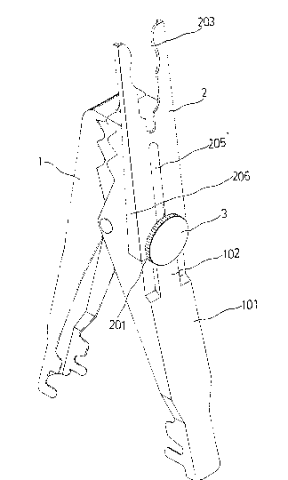
Fig. 1 illustrates a battery terminal clamp embodying the
present invention wherein the sliding clip is disposed at a
received position;
Fig. 2 illustrates the embodiment of Fig.1 wherein the
sliding clip is pushed into a clamping position;
Fig. 3 illustrates an alternate form of the present
invention wherein the sliding clip is disposed at a received
position;
Fig. 4 illustrates the embodiment of Fig. 3 wherein the
sliding clip is pushed into a clamping position;

~ ~ 3 ~
Fig. 5 is a side view of the present
invention wherein the sliding clip is pushed into a
clamping position; and
Fig. 6 is another side view of the present
invention wherein the sliding clip is disposed at a
received position.
DETAILED DESCRIPTION OF THE PREFERRED EMBODIMENTS
Referring to Figs. 1 through 4, the present
invention is generally comprised of a conventional
terminal clamp 1, and a sliding clip 2 secured to said
terminal clamp 1 at one side by a screw 3.
As illustrated, the sliding clip 2 is secured
to the clamping element 101 of the terminal clamp 1 at
the outer side by the screw 3. ~oosening the screw 3
permits the sliding clip 2 to be pushed to project over
the top edge of the terminal clamp l into a clamping
position. The clamping element 101 has a side
projection 102 for stopping the bottom edge 20] of the
sliding clip 2 when the sliding clip 2 is moved into a
clamping position, so as to stop the sliding clip 2 from
moving backward (see Fig. 5). As soon as the sliding

clip 2 is moved into a clarnping position, the screw 3 is
fastened up again to fixedlv secure the sliding clip 2
in position. When not in use, the sliding clip 2 can
be moved back to closely attach to the clamping element
101 and fi~edly secured thereto by the screw 3 (see Fig.
6).
Referring to Figs. 1 and 2 again, the sliding
clip 2 has an opening 203 at the front end thereof ~or
retaining a battery terminal, a closed, elongated
sliding slot 205 longitudinally disposed at a lower end
through which the screw 3 is inserted to secure the
sliding clip 2 to the clamping element 101 o~ the
terminal clamp 1 permitting the sliding clip 2 to slide
in longitudinal direction on the clamping element 101,
1~ and two opposite edges 206 at two opposite sides which
are bent downward through 90 angle for retaining -the
two opposite side walls of the clamping element 101.
sv means of the effect of the two opposite edges 206,
the sliding clip 2 is permitted to slide in longitudinal
direction on the clamping element 101 and protected
against torsional force.

Referr1ng to Figs. 3 and 4, there IS
illustrated an alternate form of the sliding clip 2.
In this embodiment, the sliding cli.p 2 has an opening
203 at the front end thereof for retaining a battery
terminal, an elongated sliding slot 207 extending
downward from said opening 203, and two opposite hooked
portions 20~ bilaterally disposed at the front end
thereof. When the sliding clip 2 is moved back into
a received position, t-he two opposite hooked portions
204 are respectively engaged in the ront end of the
clamping element 101 so that the sliding clip 2 will not
drop from the clamping element 101 after it is secured
in position by a screw 3. Similar to the aforesaid
first embodiment, the two opposite sides of the sliding
clip 2 are respectively bent downward through 90 angle
to firmly retain the two opposite side walls of the
clamping element 101 against torsional force.

Dessin représentatif
Une figure unique qui représente un dessin illustrant l'invention.
États administratifs

2024-08-01 : Dans le cadre de la transition vers les Brevets de nouvelle génération (BNG), la base de données sur les brevets canadiens (BDBC) contient désormais un Historique d'événement plus détaillé, qui reproduit le Journal des événements de notre nouvelle solution interne.

Veuillez noter que les événements débutant par « Inactive : » se réfèrent à des événements qui ne sont plus utilisés dans notre nouvelle solution interne.

Pour une meilleure compréhension de l'état de la demande ou brevet qui figure sur cette page, la rubrique Mise en garde , et les descriptions de Brevet , Historique d'événement , Taxes périodiques et Historique des paiements devraient être consultées.

Historique d'événement

Description Date
Inactive : CIB de MCD 2006-03-11
Le délai pour l'annulation est expiré 1994-10-03
Demande non rétablie avant l'échéance 1994-10-03
Inactive : Demande ad hoc documentée 1994-04-04
Réputée abandonnée - omission de répondre à un avis sur les taxes pour le maintien en état 1994-04-04
Exigences pour une requête d'examen - jugée conforme 1992-07-02
Toutes les exigences pour l'examen - jugée conforme 1992-07-02
Demande publiée (accessible au public) 1992-06-22

Historique d'abandonnement

Date d'abandonnement Raison Date de rétablissement
1994-04-04
Titulaires au dossier

Les titulaires actuels et antérieures au dossier sont affichés en ordre alphabétique.

Titulaires actuels au dossier
KUO-SHU LEE
KUO-SHU LEE
Titulaires antérieures au dossier
S.O.
Les propriétaires antérieurs qui ne figurent pas dans la liste des « Propriétaires au dossier » apparaîtront dans d'autres documents au dossier.
Documents

Pour visionner les fichiers sélectionnés, entrer le code reCAPTCHA :


Pour visualiser une image, cliquer sur un lien dans la colonne description du document. Pour télécharger l'image (les images), cliquer l'une ou plusieurs cases à cocher dans la première colonne et ensuite cliquer sur le bouton "Télécharger sélection en format PDF (archive Zip)" ou le bouton "Télécharger sélection (en un fichier PDF fusionné)".

Liste des documents de brevet publiés et non publiés sur la BDBC .

Si vous avez des difficultés à accéder au contenu, veuillez communiquer avec le Centre de services à la clientèle au 1-866-997-1936, ou envoyer un courriel au Centre de service à la clientèle de l'OPIC.


Description du
Document 
Date
(aaaa-mm-jj) 
Nombre de pages   Taille de l'image (Ko) 
Page couverture 1992-06-22 1 14
Dessins 1992-06-22 6 67
Revendications 1992-06-22 2 30
Abrégé 1992-06-22 1 15
Description 1992-06-22 5 131
Dessin représentatif 1999-07-07 1 11
Taxes 1993-03-03 1 27
Taxes 1993-03-03 1 24