Note: Descriptions are shown in the official language in which they were submitted.
_.
~~~~~~J
1
D.FSCRIPT ON
Titl~
Stretch Shaping Method and Apparatus
Technical Field
This invention pertains to a method and an
apparatus for shaping an elongated hollow or solid
article, and more particularly to a method and
apparatus for performing consistent, accurate spatial
dimensional shaping of an elongated extruded product.
~ackgr~"n~1 of Invention
There are a considerable number of operating
parameters and conditions present in various metal
forming methods which cause finished products to
exhibit dimensional variability. In certain processes
the dimensional variability is acceptable, while in
other processes the dimensional variability is
unacceptable and requires subsequent metal finishing
operations.
In the extrusion process, for example, a
heated ingot or billet is forced to flow under pressure
through a die opening to form an elongated article such
as a channel, a tube or an angle. In a typical
aluminum extrusion process the extruded product is
forced through the die at forces in the 500 to 15,0,00
ton range. The extrusion exits the die of an extrusion
press at elevated temperatures on the order of 300° to
1200°F. It is common to solution heat treat and quench
the extruded product in an in-line solution heat
treating process or by a separate solution heat
treatment process. Such extruded product may be made
to various lengths, including lengths in excess of 150
feet, and may be of diverse cross-sectional
configuration.
Considering the operating parameters of the
extrusion process including pressures, temperatures,
1
2
die condition and product length, and considering the
effects of subsequent heat treatment and quenching, it
is understandable that extruded metal products may
exhibit considerable dimensional variation about the
cross-section and over the length of the product. It
is also understandable that such dimensional variation
may be present from product cycle to product cycle and
from extrusion run to extrusion run. It is therefore
often necessary to perform subsequent metal finishing
operations to bring the product within acceptable
dimensional tolerance. There are same dimensional
variations on extruded metal products which are not
readily correctable by conventional metal finishing
operations, including bending, roll straightening and
hammering. In such conventional metal finishing
operations, springback is a major concern. Such
springback may be so extreme, especially in products
with substantial dimensional variation, that such
conventional metal finishing operations are
inadequate.
Prior shaping methods and apparatus have
provided methods to finish the shape of articles, such
as extrusions. The tolerances currently permissible
for such products, as published by the Aluminum
Association, particularly for thin walled extrusions,
are so broad that the products may be precluded from
certain critical applications. If the dimensional
deviation could be reduced, the products may be
applicable in an increased number of applications where
dimension is important. Furthermore, the dimensional
quality of the product in existing applications could
be dramatically increased.
Despite prior art attempts to improve the
dimensional tolerance and minimize dimensional
variation in a finishing operation, there is a need for
_..1
2~3~'~~~
3
further improvement. Accordingly, a stretch shaping
method and apparatus are desired which results in
finish shaping an elongated article, such as an
extrusion, to minimize cross-sectional and longitudinal
dimensional deviations from nominal value.
n; scW osure of Invention
This invention may be summarized as providing
an improved method and apparatus for finish shaping an
elongated metallic extrusion. The method comprises the
steps of applying axial tension to an elongated
metallic extrusion in an amount sufficient to exceed
the yield strength of the extrusion. An external
shaping die is applied against a perimetric portion of
the outside surface of the extrusion. The die has
working faces conforming approximately to a finished
cross-sectional shape for the extrusion. While
maintaining tension, the die is advanced along a length
of the extrusion. Tn a preferred embodiment an
internal shaping die may be utilized, in conjunction
with an external, shaping die, against the inside
surfaces of an extrusion.
Among the advantages of the present invention
is the provision of a method for shaping an elongated
metallic extrusion with minimal dimensional ,
variability.
Another advantage of the present invention is
the provision of a method and an apparatus for
performing consistent spatial dimensional corrections
to an extruded product in a process which involves
minimal, if any, springback.
An objective of this invention is to provide
a final shaping method which can be readily employed
in-line with an extrusion process.
A feature of the method of this invention is
that an extruded product is shaped to finished
.. . \
4
dimension without inducing significant residual
stresses in the product.
Another feature of this invention is that .
extruded aluminum product can be shaped to a
dimensional tolerance better than the dimensional
tolerance currently accepted by,the Aluminum
Association and within the tighter dimensional
tolerance currently accepted European aluminum
standards.
Another advantage of this invention is the
production of extrusions within previously unattainable
tolerance, which permits the use of extrusions in new,
dimensionally critical applications.
These and other objectives, features and
advantages of the invention will be more thoroughly
understood and appreciated with reference to the
following description and the accompanying drawings.
Briaf Descri~ti~n of the Drawinas
Figure 1 is a partial, perspective view of an
elongated, hollow metallic extrusion in the
as-extruded, solution heat treated and quenched
condition.
Figure 2 is a partial, perspective view of
the elongated, hollow metallic extrusion of Figure ,1
after stretch shaping by the present invention.
Figure 3 is a partial, perspective view of an
elongated, solid metallic extrusion in the as-extruded
and solution heat treated (quenched) condition.
Figure 4 is a partial, perspective view of
the elongated, solid metallic extrusion of Figure 3
after stretch shaping by the present invention.
Figure 5 is a perspective view of an external
shaping die.
Figure 6 is a schematic, elevation assembly
view of an apparatus of the present invention.
CA 02039705 1999-08-19
Figure 7 is a partial, perspective view of an
elongated, solid metallic extrusion of somewhat complex shape in
the as-extruded and heat treated (quenched) condition.
Figure 8 is a partial, perspective view of the
elongated extrusion of Figure 7 after stretch shaping by the
present invention.
Modes for Carrying Out the Invention
The present invention is directed to a method and
apparatus for shaping elongated products, such as extrusions,
into final dimension with close dimensional tolerance. Because
of the number and the complexity of the various operating
parameters for extruded product, including quenching, extrusions
are typically characterized by wide dimensional variability.
Such dimensional variability is due to lack of consistent
control of the extrusion and quenching process, tooling design
and maintenance, and thermal distortion. Prior reworking
processes to correct the dimensional variation were costly and
inefficient. The present invention overcomes those deficiencies
by providing a method for consistently correcting the axial and
cross-sectional dimensional variation of straight length,
elongated extrusions.
Straight length extrusions include both complicated
and simple shapes, and include complex hollow to simple solid
structures. Figure 1 illustrates a relatively simple four
walled hollow extrusion 10. Figure 3 illustrates a relatively
simple solid (open) angle extrusion 30. Preferred extrusions of
the present invention include, but are not limited to, thin
walled extrusions, i.e., those having a wall thickness of less
than about 4 mm, which typically exhibit more distortion during
extrusion and quenching than thick wall extrusions. Such
preferred extrusions
2~~~ (~~
6
include highly ductile extrusions, such as 6XXX series
aluminum alloys, and harder aluminum alloys in the 2XXX
and 7XXX series, as well as aluminum-lithium alloys.
Extrusions which are preferred for applications in the
automobile and aircraft industries and may be stretch
shaped by the process of the present invention include,
but are not limited to, 2024, 6061, 6063, 6009 and 7075
aluminum alloys.
In the process of the present invention an
elongated extrusion is stretch shaped to final
dimension. The starting workpiece is the extrusion
typically after the product has been solution heat
treated. Such extrusions are elongated, and may extend
to lengths which exceed as much as 150 feet in length.
Longer extrusions minimize the end scrap losses as a
percentage of total finished product and are therefore
desirable. An e~arusion in the extruded and quenched
condition may exhibit a warp, bow, wave, bulge or, as
shown in Figure 1, an out-of-dimension distorted
cross-sectional condition as a result of the variables
in the extrusion. and quenching process. It is
understandable that in addition to the out-of-dimension
cross-sectional configuration, as illustrated in Figure
1, the extrusion may exhibit bow, waves or twist along
the length thereof.
Such extrusions must first be put into axial,
or longitudinal, tension in the process of the present
invention. In the present invention an elongated
extrusion is transferred to a stretch shaping
apparatus. The extrusion is gripped, typically at
longitudinal end portions of the extrusion by an
appropriate gripper mechanism, such as stationary
gripper 70 and adjustable gripper 72 shown in Figure
6. It should be understood that both grippers may be
adjustable in the present invention. In a preferred
20~0~0~
embodiment the engaging faces of the gripper mechanism
match the contour and shape of the extrusion to enhance
the grip. Such gripping devices are called custom
grippers and tend to minimize or eliminate adverse end
effects by insuring that substantially uniform tension
is applied over the entire cross-section, along the
entire length of the extrusion, including the end
portions which are inbound of the gripping device. To
further enhance the grip, the engaging faces of the
gripper mechanism may be provided with a treated finish
such as a knurled or saw tooth finish, or with a
rubber, rubberized or elastomeric or polymeric surface
treatment. Certain saw tooth structures act to enhance
the holding effects as tension is applied to the
gripped product.
The gripping mechanism may be applied by any
method, but hydraulic or pneumatic clamping devices are
preferred. The extrusion may be held stationary at one
end and the other end may be pulled to provide the
required axial tension as shown in Figure 6.
Alternatively, both longitudinal ends of the gripped
extrusion may be simultaneously pulled to provide the
required axial tension. Axial tension is typically
applied using a hydraulic cylinder or mechanical drive
as the tensioning source for the force F.
What is required in the method of the present
invention is that the gripped end portions subject the
portions of the extrusion therebetween to axial
tension, or longitudinal tension, by applying
sufficient force, typically opposing force in
longitudinally opposite directions. It should be
understood that applying force in one direction while
retaining one end of an extrusion in stationary
position could also be employed to provide axial
tension greater than or equal to the yield point of the
s
extrusion. The axial tension must be sufficient to
equal or exceed the yield strength, or elastic limit,
of the material. It will be appreciated by those
skilled in the art that yield strength is a function of
the metallurgy of the material, i.e., alloy deformation
history and temper. The amount.of force required to
equal or exceed the yield strength will further be a
function of the cross-sectional area of the extrusion.
Exemplary yield strengths for extruded aluminum
products are as follows:
Aluminum Yield
_Allov Temper ~trPnath iksi)
6009 T4 24
6009 T6 91
6061 T4 21
6061 T6 40
6063 T4 13
6063 T6 31
7075 T6 73
2024 T4 47
As is explained in detail below, the shaping
of the extrusion of the present invention removes shape
.i.rregularities including bows, twists and bends in the
extrusion cross-section and length. As such surface
deformations are removed, the longitudinal length of
the extrusion ~ypically increases. Also, in the
application of the axial tension, the length of the
extrusion increases at least about 0.25 percent, due to
permanent longitudinal stretch. Permanent longitudinal
stretch experienced in applying sufficient tension to
all elements of the products for 6XXX alloys is
typically less than about 3~ permanent stretch, and for
certain alloys may be on the order. of 0.5~. For harder
alloys, permanent longitudinal stretch may exceed about
2-3~, and, for certain aluminum-lithium alloys,
26~~~~
9
permanent longitudinal strength could exceed about
6-7$. As the length of the extrusion increases, the
arial tension is held constant or varied to maintain a .
stress condition at or above the yield strength of the
extrusion. This may be accomplished by setting the
axial tension and providing suitable measuring and
controlling instrumentation to cause the gripping
mechanism to move in response, such as with a hydraulic
cylinder control, as required to maintain the
sufficient axial tension throughout the stretch shaping
operation. The combination of applying a specific
percentage of axial stretch in combination with the
shaping operation further improves tolerances by taking
advantage of the Poisson's ratio effect on the
cross-section.
Before or after the axial tension is applied
to the extrusion, an exterior shaping die 60 is applied
to an outer peripheral portion of the extrusion. The
exterior shaping die is provided with working faces
which conform to the final desired cross-sectional
shape of the extrusion. In certain instances, the
shaping die may be provided with working faces which
overcompensate for anticipated minor springback which
may be experienced in the shaping process. In a ,
preferred embodiment, the exterior shaping die is
formed of two or more portions which are applied over
the extrusion, at a location at or near one
longitudinal end portion of the clamped extrusion, and
are clamped together with a suitable clamping device
such as jack screws, or pneumatic or hydraulic clamps,
to lock the die together. It will be understood by
those skilled in the art that certain complex
extrusions will require multiple die sections to
accommodate complex cross-sectional configurations.
~fl~~~fl~
Once the exterior shaping die is applied to
the extrusion and the extrusion is in axial tension,
the exterior shaping die is advanced in either
direction, or sequentially in bath directions, along
the longitudinal length of the extrusion. It will be
appreciated that the concept of. die advance includes
the use of a stationary die through which an extrusion
which is maintained in sufficient axial tension is
passed. The die may be mounted on a traveling
mechanism, such as a rail guided car, which insures
that the die travels in a path which is coincident with
the longitudinal axis of tension of the extrusion. In
a preferred embodiment, the shaping die is mounted to a
traveling mechanism, or car, which travels along rails
which run synchronously with the longitudinal axis
along which the axial tension is being applied.
Alternatively, a cable or cables may be applied to the
die to pull the die along the longitudinal axis of
tension to shape the extrusion. It has been found that
die guides in the traveling mechanism insure minimum
deviation from the die travel direction during
shaping. The rate of travel of the die may vary, and
it has been found that speeds up to 200 feet per minute
are adequate to stay ahead of the speed of the extruder
in an in-line extrusion process. Die speeds up to 400
feet per minute has no adverse effects on the shaping
process based on theoretical evaluations. The working
faces of the die act to work the exterior walls of the
extrusion to plastically deform aluminum extrusions
within or better than the standard tolerance currently
established by various American and European
associations including the Aluminum Association. In a
preferred embodiment, the process of the present
invention typically brings the finished extrusion to
within less than half of the current standard tolerance
y
11
established by the Aluminum Association for aluminum
extrusions.
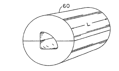
The exterior shaping die such as two piece
die 60 shown in Figure 5 of the present invention must
be of sufficient strength, and there must be sufficient
Iubricity to permit plastic deformation in working and
reorientation of the material of. the extrusion.
Exemplary die materials for the working faces of the
die include, but are not limited to, steel alloys, zinc
alloys, graphite impregnated nylon and certain epoxy
die materials. A preferred die material is a cast zinc
alloy sold under the trade name Kirksite.
The axial length L of the die 60, as shown in
Figure 5, must be sufficient to work the extrusion
material. It has been found that the die length should
exceed about 0.5 inch and may exceed 12 inches. It
will be appreciated that multiple dies may be utilized
in the present invention to shape extrusions in
stages.
In one embodiment the axial tension applied
to the extrusion may be slightly less than the yield
strength of the extrusion, such as at 90~ of the yield
point. However, the action of the advancing shaping
die may be adequate to cause the total axial tension to
which the extrusion is exposed to exceed the yield
point of the extrusion and thereby cause the extrusion
to be shaped into dimensional conformity as the die is
advanced.
In a preferred embodiment of stretch shaping,
there should be adequate lubricity to permit the die to
travel freely along the extrusion and perform localized
deformation of the extrusion. Such lubrication may be
provided in the die material such as through the use of
certain epoxy material or through impregnation with
materials such as graphite. Alternatively, a thin film
2~3~'~~~
12
of medium weight lubricant may be applied separately or
automatically ahead of the die such as from an
applicator that may be integrally attached to the
travelling mechanism, to the extrusion to enhance the
process with a minimum surface residue. Lubrication
reduces variations in axial force of the die on the
axial tension control system, and also improves surface
appearance.
In a preferred embodiment an interior shaping
die may be employed with hollow portions of
extrusions. Such interior dies could be employed
independent of, or simultaneously with, the exterior
shaping die to improve and enhance the final
dimensional tolerance of the extrusion. In some cases
an external and an internal die combination can be used
in axial alignment to one another during shaping to
enhance deformation. An interior shaping die conforms
substantially to the finished inside cross-sectional
shape or dimension of a closed or substantially closed
extrusion. A cable mechanism is typically employed to
pull the interior shaping die and thereby advance the
die through the extrusion along a path coincident with
the axis of axial tension.
In another embodiment hollow chambers of .
elongated extrusions may be filled with a fluid to
provide uniform pressure against the inside walls of
the extrusion along the length thereof as an exterior
shaping die is advanced along the length of the
extrusion. Such internal fluid and pressure may be
provided such as by the method disclosed in U.S. Patent
4,704,886, the contents of which are incorporated
herein by reference. However, the internal pressure of
this embodiment may be utilized intentionally prior to
advancing the shaping die to outwardly bulge surfaces
of a hollow extrusion, which outwardly bulged surfaces
2039705
13
may be subsequently worked into dimensional tolerance
witra the use of an external shaping die. In instances
where such pressure is utilized to deform the
extrusion, such pressure is typically released prior to
the subsequent working with the external shaping die by
the process of this invention. The process of the
present invention is typically performed at ambient
temperatures but may be performed in certain cases and
with certain alloys at elevated or at lower
temperatures, such as to maintain or alter temper
during deformation.
After the extrusion is shaped under axial
tension, the exterior shaping die is opened, the
tension is relaxed, or vice versa, and the extrusion is
removed from the apparatus. The extrusion should be
able to be stretch shaped and removed within the time
it takes to extrude product to such length. Therefore,
the method of the present invention could be utilized
if desired as an in-line process for typical extrusion
operations.
The stretch shaping process of this invention
may also be employed on multiple extrusions
simultaneously. In such embodiment, multiple
extrusions may be placed and maintained in axial
tension with one, or more, gripping devices. With the
multiple extrusions in axial tension, above the yield
strength of the material, an external shaping die,
which may be constructed as a unitary die assembly caith
multiple shaping ports, is advanced along the length of
the multiple extrusions. The die ports have working
faces which conform approximately to the finished
cross-sectional configuration of the respective
extrusion which fits in such port during stretch
shaping.
2~39~~
14
In another embodiment the stretch shaping
invention may be employed to partially reshape
extrusions. For example, certain extrusions cannot '
readily be made to final desired configuration due, for
example, to limitations in extrusion tooling. Yet, by
the process of this invention, such desired
configurations may be obtained by a stretch shaping
operation. For example, Figure 7 illustrates a partial
perspective view of a somewhat complex shaped extrusion
80. Figure 8 illustrates a final desired configuration
for the extrusion 80 shown in Figure 7. Such final
desired configuration may be accomplished by advancing
a die having working faces conforming substantially to
the final desired crass-sectional configuration of the
extrusion, along the longitudinal axis of the extrusion
while the extrusion is in axial tension above the yield
point of the extruded material. Such shaping brings
end portions 82 and 84 in close proximity to one
another along the length of the extrusion, which final
configuration may not be readily obtainable in an
extrusion process. In addition to closing portions 82
and 84, the stretch shaping operation accurately
corrects other dimensional deviations that may need
correcting along the length of the extrusion, such as
bows, twists or bends. Likewise, the stretch shaping
method may be employed, for example, to shape extruded
flanges where it may be desirable to create shaped
pockets or envelopes to house wire, cable or the like.
This invention provides a method of
performing consistent spatial dimensional corrections
to an elongated extruded product with an in-line
electro-mechanical apparatus without inducing
significant residual stresses in the extrusion. In any
event, the residual stresses created by the stretch
shaping method are less than the stresses normally
2a39'~~~
created by alternative local deformation operations and
shape reorientation methods.
What is believed to be the best mode of the
invention has been described above. It will be
apparent to those skilled in the art that numerous
variations of the illustrated and described details may
be made without departing from the scope of this
invention.