Note: Descriptions are shown in the official language in which they were submitted.
_~-
TOP ~I~OR A ~iA~JL E'IEIa I~ 1~, ~~~CE D7CVIDER SYSTEM
F~AAICOFtOUND O,~' TFIE INVENTIAN
1. Field of the Invention
The present inventian relates generally to wall
partitions in a space divider system, and more
particularly, to a top cap on the wall partition.
2. Scope of the Prior Art
Space divider systems comprising wall
partitions or panels arranged end to end on the floor and
supported by depending leg supports provide the user with
great flexibility in arranging and rearranging work areas
to meet changing activities. Installing an energy supply
and communications system within the wall panels has
proven to be a convenient and efficient method of
providing individual work areas with electricity and
communications service. Providing such electrical wiring
systems within a channel in a top edge of wall panels is
known. Typically, a top cap serving as a cover member is
used to enclose the channel at the top edge of the panel,
and also serves to provide an aesthetic trim finish to
the wall panel top edge.
A top cap usually is associated with a single
panel or partition, and has a length essentially equal to
the length of the panel. Top caps are frequently
extruded U-shaped pieces, and thus have exposed openings
at the respective ends of the top cap. Separate caps are
usually provided at the panel joints and an end cap is
provided at the end of a panel run.
SUMMARY OF TIME INif'ENTION
In accordance writh the invention, a space
divider system comprises at least two portable upright
panels horizontally serially aligned sa that vertical
ends of the panels are positioned in close proximity to
one another, Each of the panels has a top cap having a
channel with an open end, and the open end in the top cap
of one of the panels is diseased opposite the open end on
the top cap of the other panel. A pair of end inserts is
provided wherein one of the pair is received within the
channel of one top cap, and the other of the pair is
received within the channel of 'the other top cap. Each
end insert has a resilient distal portion extending from
the open end of a respective top cap so that the distal
ends are positioned in close proximity to one another.
The end inserts provide visual continuity at the
interface between panels.
Preferably, one of the inserts comprises a tail
member mechanically joined to an extension member. The
extension member carries the distal portion and the tail
member is received within the channel.
In another aspect of the invention, an end insert is
provided for a top cap on a wall panel. The wall panel
typically has a top edge, and the top cap covers a
portion of the top edge. The cap typically has a channel
with an open end, and the end insert comprises an
extension member removably joined to a tail member. The
tail member is received within the channel of the cap,
and affixed to the top cap. The extension member has a
distal portion extending away from the open end.
In another aspect of the invention, the end
insert comprises a first member having an extended
flange, a second member adapted to be received within the
channel and fixedly mounted to the top cap, and means for
removably connecting the first member to the second
member so that the flange extends away from the open end
when the second member is received is received from the
channel.
Preferably, the first member is an elastomer,
and has a stop flange which abuts the open end when the
first member is connected to the second member.
In connecting the two members, the first member
has a coupling flange having an aperture therethrough,
and the second member has a ledge which has a stub of a
diameter so that the stub can be press fit into the
aperture. Another aspect of the connection is
characterized by a groove on one side of the coupling
flange, and a rib on a surface of the ledge so that the
groove is adapted to receive the rib. Preferably, the
second member is formed of a rigid plastic and has a tab
-~_
extending therefrom with the tab secured to the top cap
by ultrasonic welding or chemical bonding.
In another aspect of the invention, the
extension member. and the tail member can be joined
together and utilized as a connector between two
adjoining top caps wherein the tail can be affixed to the
first cap, and the extension member will have a distal
portion extending away from the end of the first cap and
slidably received within a second channel of the second
cap so that the stop flange is interposed between the two
adjoining open ends. In this configuration, the first
and second caps and the stop flange present a visually
continuous line.
BRIEF DESCRIPTION OF THE DRAWINGS
The invention will now be described in
accordance with the following drawings in which:
FIG. 1 is an exploded view of a portion of a
wall panel with a top cap, with an end insert according
to the present invention:
FIG. 2 is an elevational view of two adjoining
panels incorporating top caps and end inserts of the type
illustrated in FIG. 1, partially in cross section, and
partially broken away to show detail:
FIG. 3 is a plan view of the wall panels of
FIG. 2, with portions partially broken away to show
detailt
FIG. 4 is a sectional view taken along line 4-
~ of FIG. 2F
FIG. 5 is an elevational view similar to FIG. 2
showing another embodiment of a wall panel incorporating
the invention.
DESCRIPTION OF THE PREFERRED Ei~IBOISII~IE1VT
Referring now to the preferred embodiment
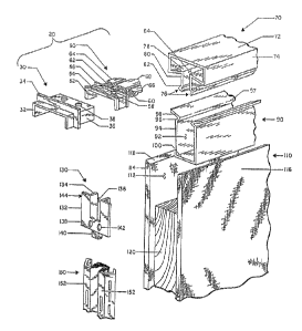
illustrated in the drawings, and specifically to FIG. 1,
an end insert 20 for a top cap 70 comprises a separable
two-piece body formed of a extension member 3o which is
adapted to be joined to a tail member 50. The tail
member 50, in turn, is adapted to be received by the tap
cap 70 in a manner to be described hereinafter.
_4-
The top cap 70 has two opposed sexing flanges
76 joined together by a web 72. Tt will be understood
that the web 72 may be of any shape consistent with the
aesthetic lines of the wall panel 3.10 to which it is
attached. In the illustrated embodiment, the web 72 is
boxlike, having a flat top '73, and two opposed sides 74.
Other shapes, for example, might include a U-shaped web
72 without defined sides 74. Tn any event, the web 72
and the spring flanges 76 define a channel 84.
Preferably, the top cap 70 is formed of extruded plastic.
Each spring flange 76 comprises an inwardly
directed flange 78 which extends inwardly from the web 72
to partially define the channel 84, and a downwardly
extending flange 80, which extends downwardly roughly at
an acute angle relative to the inwardly directed flange
78. A longitudinal rib 82 is disposed on the downwardly
extending flange 80. The downwardly extending flanges 80
are adapted to be received in a snap fit engagement by a
channel liner 90 which is disposed within a wire
management channel 112 defined by opposed faces 116 of
the wall panel 110.
The channel liner 90 is generally U-shaped,
having side walls 94 and a bottom wall 100 which define a
channel 92. The side walls 94 are joined to an inwardly
directed portion 96 terminating in a locking edge 97,
which in turn is connected to an outwardly directed stop
flange 98. Tt will be seen that the channel liner 90 is
readily received within the wire management channel 112
of the wall panel 110 so that the stop flanges 98 come to
rest on upper edges 118 of the panel surfaces 116. The
channel liner 90 is secured to the wall panel 110 by
suitable fastening means. As with the top cap 70, the
channel liner 90 may be formed of plastic, particularly
in view of a need to provide additional electrical
insulation to the Wire management channel 112.
The top cap 70 is thus adapted to cooperate
with the channel liner 90 by being snap fitted in a
downward direction to become securely locked with respect
to the channel liner 90 as shown in FIG. 4. This
~~~~3~
_5_
assembly is achieved merely by moving the top cap 70 from
the position shown in FTG. 1 downwardly until the ribs 82
engage the locking edges 97 of the channel liner 90, at
which time continued downward pressure upon the top cap
90 will cause an inwardly directed deflection of the
flanges 80 until the ribs 82 are beneath the locking
edges 97 whereupon they will spring outwardly toward the
side walls 94 of the channel liner 90 in a snap fit
engagement.
The wall panel 110 typically also includes a
side edge 114, which has a hardware channel 120 partially
defined by the panel sides 116. A frame hanger 150
having face portions 152 and slots 154 is securely fitted
within the hardware channel 120. As can be
seen in Figs. 1 and 2, a wedge block 130 is disposed at
the conjunction of the hardware channel 120 and the wire
management channel 112. The wedge block 130 is generally
U-shaped having stop flanges 132 and alignment flanges
134. The alignment flanges 134 generally define a U-
shaped channel 136 which corresponds in shape with the
channel 92 defined by the channel liner 90. A base 138
of the wedge block 130 includes a spacer block 140 and a
pair of apertures 142. The wedge block is typically
mounted adjacent the frame hanger 150, at least partially
within the hardware channel 120 so that the alignment
flanges 134 will abut the edges of the channel liner 90.
The block 130 may be secured by screws disposed
through the apertures 142 or by any other suitable means
not pertinent to this invention. generally, the face of
the stop flange 132 lies in a plane with the face 152 of
the frame hanger 150, maintained in such position by the
spacer block 140. Tt will thus be seen that the top cap
70 provides a visually continuous horizontal edge at the
top of the panel, and the frame hangar 150 and wedge
block 130 provides a visually continuous vertical line at
the side edge of the panel. The end insert 20 according
to the invention provides a suitable finish to the
corner, particularly carrying forward the vertical line
of the side edge.
°
-6-
Referring again to FIG. 1, the extension member
30 of the end insert 20 is preferably formed of a
resilient elastomer. An example of a suitable elastomer
is an olefin based thermoplastic rubber having a low
durameter in the range of 55-70. A suitable
thermoplastic rubber is sold by Shell Oil Company as
KRATON, Shell $7705. The extension member 30 includes a
distal portion 32 extending outwardly from a stop flange
34. A coupling flange 36 extends from the step flange 34
in a direction apposite that of the distal portion 32.
The distal portion 32 and the coupling flange 34 are
generally U-shaped, each with an outside surface that
conforms generally to the shape of the top cap channel
84. A pair of coupling apertures 38 are located in the
coupling flange 36, and a groove or channel 40 is located
on the underside of the coupling flange 36 between the
coupling apertures 38 and the stop flange 34 (see FIG.
2). A shoulder 41 is disposed near the peripheral edge
of the coupling flange 36.
The tail member 50 is preferably formed of a
hard plastic material and includes a U-shaped ledge 54,
complementary in shape to the coupling flange 36 of the
extension member 30. The peripheral edges of the ledge
54 include upwardly extending ribs 52, 56. A suitable
plastic.material is a high-impact ABS sold by General
Electric Company under the name of CStCOLACAR resin. A
pair of studs 58 extend upwardly from the base 54
intermediate the ribs 52, 56. Each stud is dimensioned
so that it can be press fit into a corresponding coupling
aperture 38. Several spacing flanges 60 extend axially
from the ledge 54 away from the rib 56. Each flange 60
is strengthened by a gusset 62. Extending further
axially from the spacing flanges 60 are connecting tabs
64, 66, and 68.
Referring now 'to FIGS. 2-4, it will be seen
that the extension member 30 is adapted to be coupled to
the tail member 50 by a snap fit engagement wherein the
studs 58 are received by press fit into the coupling
apertures 38, and the ribs 52, 56 are received by the
_.
groove 40, and shoulder 41, respectively. Thus, the end
insert 20 will have rigid plastic tabs 64, 66, 68
extending from a resilient distal portion 32 and the stop
flange 34. The assembled end insert 20 is then affixed
to the open end of the top cap 70 by inserting the tail
member 50 and the associated coupling flange 36 into the
channel 84 of the top cap 70 untzl the stop flange 34
contacts the edge of the top cap 70. The connecting tabs
64, 66, and 68 are disposed to engage the inside surface
of the top cap 72 where they may be ultrasonically welded
thereto (see FIG. 4).
Referring now to FIG. 2, when two panels 110
are disposed adjacent to each other, it will be seen that
the top caps 70 an each panel can have end inserts 20
which will likewise be disposed adjacent to each other.
The resiliency provided by the elastomeric extension
member provides for flexibility in the connection between
the adjoining panels and top caps. Thus, for example, if
the lengths of the respective top caps 70 were slightly
too long for the respective panels, the adjacent end
inserts 20 would be in contact, and the extension members
may be slightly compressed. Conversely, if the top
caps 70 were slightly too short, there may be a slight
gap between the extension members 30, but the shape of
25 the end inserts 20 would nevertheless carry the visual
lines of the top caps 70 and frame hangars 150 arid thus
maintain the aesthetic appearance of the panels.
It will also be understood that the
complementary shape of the distal portion 32 enables it
30 to be received directly into an adjoining tap cap up to
the stop flange 34 as shown in FIG. 5. The stop flange
34 will preferably have an edge which is complementary in
shape to the outside surface of the top cap 70 so that
the two adjoining top caps may be joined together by a
single end insert and the visual continuity of the
exterior surface of the top cap can be maintained. Thus,
two short lengths of top cap may readily be connected on
a single longer panel 110.
~~~~~a
_8_
Reasonable variation and modifications are
possible within the scope of the foregoing disclosure and
drawings without departing from the spirit of the
invention which is defined by the appender~ claims.