Language selection

Search

Patent 2040052 Summary

Third-party information liability

Some of the information on this Web page has been provided by external sources. The Government of Canada is not responsible for the accuracy, reliability or currency of the information supplied by external sources. Users wishing to rely upon this information should consult directly with the source of the information. Content provided by external sources is not subject to official languages, privacy and accessibility requirements.

Claims and Abstract availability

Any discrepancies in the text and image of the Claims and Abstract are due to differing posting times. Text of the Claims and Abstract are posted:

  • At the time the application is open to public inspection;
  • At the time of issue of the patent (grant).
(12) Patent: (11) CA 2040052
(54) English Title: ROCK DRILL
(54) French Title: MARTEAU PNEUMATIQUE
Status: Deemed expired
Bibliographic Data
(52) Canadian Patent Classification (CPC):
  • 255/68
(51) International Patent Classification (IPC):
  • E21B 10/00 (2006.01)
  • E21B 10/44 (2006.01)
  • E21B 10/56 (2006.01)
  • E21B 10/58 (2006.01)
(72) Inventors :
  • RUMPP, GERHARD (Germany)
  • OBERMEIER, JOSEF (Germany)
  • FUENFER, JOSEF (Germany)
(73) Owners :
  • HILTI AKTIENGESELLSCHAFT (Liechtenstein)
(71) Applicants :
  • RUMPP, GERHARD (Germany)
  • OBERMEIER, JOSEF (Germany)
  • FUENFER, JOSEF (Germany)
(74) Agent: GIERCZAK, EUGENE J. A.
(74) Associate agent:
(45) Issued: 1998-09-29
(22) Filed Date: 1991-04-09
(41) Open to Public Inspection: 1991-10-10
Examination requested: 1996-01-26
Availability of licence: N/A
(25) Language of filing: English

Patent Cooperation Treaty (PCT): No

(30) Application Priority Data:
Application No. Country/Territory Date
P 40 11 441.4 Germany 1990-04-09

Abstracts

English Abstract


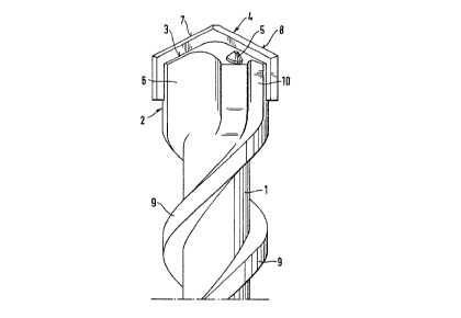
A rock drill has an axially extending shank (1) with
a drill head (2) on one end. The drill head (2) has an end face
(3) with a cutting blade (4) and cutting pins (5) extending
outwardly from the and face in the drilling direction. The
cutting blade (4) extends, diametrically across the end face and
projects radially outwardly from the drill head (2) said axially
outwardly from the end face (3). The cutting pins (5) are
arranged on a diameter of the drill head which forms an acute
angle relative to the cutting blade (4). Due to the acute angle
between the cutting pins and the diametrically arranged cutting
blade, removal grooves extending axially from the end face can
be enlarged.


French Abstract

La présente invention vise une perforatrice de roches munie d'une queue en saillie sur le plan axial (1) et d'une tête porte-forêt (2) à une extrémité. La tête porte-forêt (2) présente une surface terminale (3) dotée d'une lame de raclage (4) et de broches coupantes (5) se prolongeant au-delà de la surface terminale, vers la zone d'attaque. La lame de raclage (4) se prolonge diamétralement hors de la surface terminale et excède la tête porte-forêt (2) sur le plan radial, dans l'axe externe de la surface terminale (3). Les broches coupantes (5) sont disposées au périmètre de la tête porte-forêt de manière à former un angle aigu par rapport à la lame de raclage (4). Comme les broches coupantes et la lame de raclage diamétralement opposées forment un angle aigu, il est possible d'élargir les rainures de dépose faisant saillie sur le plan axial par rapport à la surface terminale.

Claims

Note: Claims are shown in the official language in which they were submitted.


The embodiments of the invention in which an exclusive
property or privilege is claimed are defined as follows:


1. A rock drill having an axis extending in a drilling
direction and having a rotational direction, said
rock drill comprising an axially extending shank
and a drill head having an outside diameter and
located at and extending axially outwardly from a
first end of said shank, said shank having an
outside surface, said drill head axially aligned
with said shank, said drill head having an end face
extending transversely of the drilling direction, a
cutting blade mounted in said drill head and
extending diametrically across said end face
traversing the axis of said drill head and extending
axially from and radially outwardly beyond the
outside diameter of said drill head, and at least
two cutting pins mounted in and extending outwardly
from the end face of said drill head, a helical rib
extending around and outwardly from the outside
surface of said shank from the first end thereof
away from said drill head wherein the improvement
comprises that said cutting pins are each located
on a single straight line extending through the axis
of said drill head with the straight line spaced at
an acute angle (a) from the cutting blade said
cutting pins are located on the single straight line
each on an opposite side of said cutting blade and


said cutting pins are rotationally symmetrical
relative to the shank axis and are located in a
radially outer edge zone of said drill head, said
drill head having axially extending removal grooves
extending from the end face of the drill head to
adjacent the first end of said shank for conveying
drilled material for passage along said shank and
helical ribs, said removal grooves comprising first
removal grooves having a larger angular extent than
second removal grooves , and in the rotational
direction of said rock drill the first removal
grooves trail said cutting pins and the second
removal grooves lead said cutting pins on each of
the opposite sides of said cutting blade .

2. A rock drill, as set forth in claim 1, wherein the
equal number of said cutting pins are located on
each of the opposite sides of said cutting blade.

3. A rock drill, as set forth in claim 1, wherein the
acute angle (a) is in the range of 40 degrees to 70
degrees.

4. A rock drill, as set forth in claim 1. wherein said
cutting pins are inclined outwardly in the drilling
direction relative to the shank axis.


5. A rock drill, as set forth in claim 1, wherein said
end face is conically shaped with the apex of the
coni. cally shaped end face located on the axis of
said shank, said cutting blade has an apex located
on the axis of said shank with a pair of cutting
edges inclined outwardly from the apex with the
inclination being opposite to the drilling
direction, said cutting pins having leading ends
facing in the drilling direction and projecting
outwardly from said end face of said drill head,
said cutting edges forming a conically shaped plane
as said rock drill rotates about the axis of said
shank, and the leading ends of said cutting pins
located between the rotational plane of said cutting
edges and said end face.


6. A rock drill, as set forth in claim 5, wherein the
leading ends of said cutting pins are spaced in the
range of 0.3 mm to 1.5 mm from the rotational plane
of said cutting edges.


11


Description

Note: Descriptions are shown in the official language in which they were submitted.


0~5~
B~CK5~<0~ ~:~ T~ INV~hLll:)N


The presPnt inventiQn is directed ~o A rc~c:k drill with
a drill head at one end o~ ~n axially extending ~hank~ A cutter
blade extends dîam~txically a~ross and p~oj~ct~ ~adially
outwardly ~rom the dri 11 head and at least two cut~er pins
ex~en~l ou~w~rdly ~rom ~he ~rill h~d end ~ace in th~ drilling
dire~::tion .


RoGk drills ar~ used :~or cutting holes ~r }:~ores in
rock, c:onc:ret~, masonry and the like and serve for receiviny
faste~ing mem~ers, as passages ~or pipes or cables as well as
for ~xplosi~res in ~lasting op~r~ti4ns~ Roc:k drills ha~ing a
com~ination o~ cu~ing. I~lades ~nd cut~ing pins have the
a~vaslta~e tha the drilled material or drillings rernoved by the
autting blada are fuxther c:omminu~ed by ~h~ cutting pins. Such
ro~-k drills are dis~lo~ed in l:)E~OS 35 44 433. ~or a vari~ty o~
working c~nditions, the ~utput l~vel o:~ such known roGk drills
i~, s~tisfac~ory. Unde3~ certz~in c)perz~ting conditions, however,
the ramov~l of the drillings ~nd the ~d of ~h~ ro~ drill is
not optimum.


SUMMP.RY OF TX15 l~v~ N
.


The priT~a~y objec~ h~ pxesen~ inven~ion is 'co

provide a rocX drlll ena~lin~ ~dditiorlal comminut~on o~ th~
~' .
.. , , ~


, :
~. ' ~' ' ' '
.

5;~
drillings at a high ma~erial ~rilling rat~, while a~ordizlg ~n
improved removal o~ the d~illings~

In acoordanc:~ with the present lnvention, ~h~ impro~ed
op~ra~ion is ~ hieved by loc!ating the cutting pins on a diame~er
Olc the ~rill head pO~;itiOh~d a~: an acutQ angle wi~h the
diamet~ically extendin~ cutting blade. ~ue ~o the ~rrangement
of the cu'tti~g pin~ in ~s~caoraan::e with ~he presen~ in~en~lon, an
enlargemen~ of the drilled rA~, ~rial removal grooves is obtained.

AdYantageously, t~e cuttin~ pins are loc~ed on both
o~ the apposite sid.es of th~ cu~tlng ~lade. Accordi~n~ly, a
symme~xi ::al arrangemen~ ls possi}: le.
.


This feat~re i~; partic:ularly applic~ when the
nunber o~ ou~tting pins is equ~l Oh }~oth side~ o~ the cu~ter
blade . with an equal number of ~ut~ing pins on the opposi te
sides of the ~u~ing blade, ~ more uni~m c:on~nunltion of ~he
dri~lled mat~rial is g~ ned alo~g with a ~mo~t~er opera~ion of
the rock drill.

By loca~ing two cutting pins in the r~dially outer
edge zone oP ~he d~ill head, ~n ~dditional c~n~erirl~. e~f~t of
the roc}; drill is obt~in~d during ~he drilling oper~tion.
.. . .


,
. - . : '

. , .

: . ,.

5;2
Preferably, the ou~ting pi~s are arr~r.ged rc~l:ationally
symm~tri~al t~ ~xi~ he shank. Suc~ ~n arrangement ~s~ures
an improved operati~ smoothnes.s of the ro~k d~ along wlth
a ~?recise d~illing geom~ry~


In a preferred ~rrarlgeme~ he a~u~ ~ngle between
the diameter on whic:h the cutting pins ~re located ~nd the
dia~[ etrically arranged cutter ~lade is ln the rar~ge ~ 4 0~ to
70~. Such an angular range has p~oved especially sati~acto~y,
~ec;~use the arr~ngement of ~uf~ ien1~:Ly l~rge removal gr~ove~ i~
particularly favora~le in the ~nd fa~ o~ ~he drill head in the
~e~ion o~ the compl~men~ry o}~tuse angle.


A hel i~al rib. ~dj oins ~h~ remov~l groo~e with the
heliaal ri~ del:erminin~ ~h~ dix~c~tion o~ ro~a~ion o~ ~he rock
drill~ The acute anyle ~orme~ by the ~iametri~ally ~rr~ ed
cutter hlad~s and the diamet~r on which ~he cut~:~ng pins are
loc:ated is preferahly ~rranged on the sid~ ~ ~he cutting bl~de
~ral lin~ in th~3 ro~ational dir~ion.

~, .

e~pecially e~ec:~ive ~or the c:ommi~utic~ o~ the
dri~led mate~i~l, to arrange the cut~ing pirls inoline~l outwardly
rela~i~e ~o th~ :shank axis, howe~r, th~ ~rr~ncJement o~ the
cu~ing pins p~rallel to ~he ~hank ~xi~ lso po~qlble~


The le~ding ~nd ~aces o~ the cutting pin~; pc~lnting in
the drilling direction pre~arably do nc)t lie on th~ c:onic:al

. ,~ .

,

5i~
rotational plane ~ormed by the cu~ting edg~ of khe ~ut~ing
blade, rather t.hey arR o~ t re~rwardly ~rom ~uch plane~ ~or
example, in the range o~ o. 3 D to 1 ~ 5 mm. Accordingly, ~h~
feed ~elocity during th~ drilling operati~ ls more ~ni~orm,
sinc~ th~ cutting pins contact ~ sur~c~ of the m~t~ri~ being
drilled ~t nearly the sam~ poin~ in tim~ as ~h~ cuttlng blade~

~ s a re~ul~, a mo~ uni~o~m removal o~ th~ drilled
m~teri~l is a~tained. In ad~iti~n, ~he ~u~ing p~n~ ~$sUme an
abutmen~ function *or the dr~ll head ih ~he d~illin~ dir~s~ion.

The v~riou~ f~atures of novelty which ch~r~ct~rize the
invention are pointed out with partiaular~y in the claim~
annexed to and ~orming a yart of this disclo~ur~. ~or a better
under~tanding o~ the inv~n~ion, i~5 operating advantages and
spa~ifi~ obiec~s aktain~d by i~s use, referance ~hould be had to
the a~aompanyin~ dr~wings and descrlptive matter ih which ~her~
are illustr~ed an~ de~cribed pre~erred embodiments ~ the
inven~ion.
DE8CRIP'rI0~ 0~ T~E t:~R~WIN~;

In the dr~wing:
Fig~ 1 is a partial axially extending ~iew of a ro~
dr~ 11 embodying the present inventiont


, .


~''' ,.

Fig. 2 is arl en~ ~:Lew of the rock drill a~ ~hown in
F ig . l; an~


Fi~ n ~xially ex~ending sec~ional view ~hrough
~he rock drill in Figs. 1 and 2, t~}c~n ;~long ~hB lin~ I in
~i~. 2.


DETAII. I)~:~CRIP~ION OF q?~35 1~1y~ 1 ON


In Figs. 1, ~ ~nd 3 ~ rock drill is shown comprisin~
an axiall~ extPncling shan}c ~ with a drill head ~ ~rmed on one
erd o~ the ~hahk~ Sh~nk 1 has a h~lic~l rib g pro~ecting
o~l~war~ly from i~ outer. sur~ce ~or guiding the drill in a hole
3:eing drilled and also ~or ~iding in the removal of the drilled
material or drillings. Drill heaA 2 ha~ ~xially extending
removAl grooves ~, 10 exten~n~ from ~he end ~ace 2 o~ ~he drill
head ~nd ~erving far conveyir~g the drillings ~x~m ~h~ end f~e
opposite ~o ~h6~ drilling direction ~ow~r~ the sh~nk 1. A
dia~rically positioned cut~in~ blade 4 extends a~ross ~he ~nd
~ace ~ of the drill head ~ CU~ti~g blade 4 pro~ s axially in
the drilling ~ire~tion ~ron~ the end ~c~ o~ the drill head an~
al o proj ects r~dially ~utwardly ~om the circum~enc~ of th~
drill hea~. A pair ou~ting pirls ~ a~e ~ecure~ in the drill head
and extending outwardly from the end ~oe. Ilhe outtin~ pi~s 5
are located on ~ ~ia~nete~ o~ the drill head wh1ch ens: loses an
acute angle a with the diametricAlly arranged cuttirlg ~lad~ 4.
. ...

.,, ~


,

; ;

Aaute ~ngl~ a, shown in ~iy. 3, is ~ormed with ths side o~ ~h~
cu~ting b},ade trailing in the ro~ional direç~ion 1:~.


In the sec~ion~l view a.~:fo~ded ir~ Fig~ 3, i~ i~ shown
~l~arly ~h~ the cut~in~ pin~ 5 are incline~, ou~wardly ~rom the
shank ~xis in the drilling dire~tion. The cutting pins 5 ar~
embe~ed in~o the drlll he~.d 2 so t:h~ the leading ends of the
cutting pl~s ~ pra; ect ou~wardly from the e~d ~ e 3 bu'c ar~
located l~ tween the ~nd ~ace and the c~onic:al plane formed by ~he
inal ~ ned c~ttinq ed~e~ 7, 8 vf the cll'cting bladé 4 .


While the illustrated embodiment ~haws one pair of
¢ut~ing pin~ 5, ~ditional pair~ ~an be p~ovided. The 2~rrange~
Flen~ of ~he c:ut~ing blade 4 and the ~utting pins ~ is symmetri-
c~al in the r~t~ional direction.


As disp~ayed in Fig. 2, th~ rock drill ro~a~es counter
clo~kwise, note the rota.ti4nal direc~ion ~~, so that the cu~ing
edge 7, as i~ moves in ~he rotational direo~ion D, is followed
by the remov~ oc~ve 10, the c~u!:ting pin 5, the removal groove
~, and then ~he ~ut~ing ~dg~ 8 whiah, in turn, is ~ollowed by
the xemoval groove lO, the c:utting pin 5, and ~he removal'~roove

~. . . ..


., 7

2~ 5~
. .

~ s can be nv~d in Fig. ~, the angular ex~ent: of ~che
rem~val ~rooves 6 is ~nlarged duQ to th~ angul~r po3ition o~ t~
ing pin~; 5 r~lative -to the ~u'c~ing blad~ 4~

While specifio ~odimehts o~ the inv~nt1on hav~ ~een
shown lnd ~esoribed in detail to i~ st~rate the ~pplica~ion of
the inv~ntive p~inciple9, it will be under~ood th~t the
invention may be embo~i~d oth~ise wi~hout depa~tin~ fro~ ~uçh
princ ipl~s ~


, . 8

Representative Drawing
A single figure which represents the drawing illustrating the invention.
Administrative Status

For a clearer understanding of the status of the application/patent presented on this page, the site Disclaimer , as well as the definitions for Patent , Administrative Status , Maintenance Fee  and Payment History  should be consulted.

Administrative Status

Title Date
Forecasted Issue Date 1998-09-29
(22) Filed 1991-04-09
(41) Open to Public Inspection 1991-10-10
Examination Requested 1996-01-26
(45) Issued 1998-09-29
Deemed Expired 2003-04-09

Abandonment History

There is no abandonment history.

Payment History

Fee Type Anniversary Year Due Date Amount Paid Paid Date
Application Fee $0.00 1991-04-09
Maintenance Fee - Application - New Act 2 1993-04-09 $100.00 1993-04-08
Maintenance Fee - Application - New Act 3 1994-04-11 $100.00 1994-04-05
Maintenance Fee - Application - New Act 4 1995-04-10 $100.00 1995-03-31
Maintenance Fee - Application - New Act 5 1996-04-09 $150.00 1996-03-19
Registration of a document - section 124 $0.00 1997-01-23
Maintenance Fee - Application - New Act 6 1997-04-09 $150.00 1997-03-19
Maintenance Fee - Application - New Act 7 1998-04-09 $150.00 1998-03-16
Final Fee $300.00 1998-05-21
Maintenance Fee - Patent - New Act 8 1999-04-09 $150.00 1999-03-18
Maintenance Fee - Patent - New Act 9 2000-04-10 $150.00 2000-03-16
Maintenance Fee - Patent - New Act 10 2001-04-09 $200.00 2001-03-16
Owners on Record

Note: Records showing the ownership history in alphabetical order.

Current Owners on Record
HILTI AKTIENGESELLSCHAFT
Past Owners on Record
FUENFER, JOSEF
OBERMEIER, JOSEF
RUMPP, GERHARD
Past Owners that do not appear in the "Owners on Record" listing will appear in other documentation within the application.
Documents

To view selected files, please enter reCAPTCHA code :


To view images, click a link in the Document Description column. To download the documents, select one or more checkboxes in the first column and then click the "Download Selected in PDF format (Zip Archive)" or the "Download Selected as Single PDF" button.

List of published and non-published patent-specific documents on the CPD .

If you have any difficulty accessing content, you can call the Client Service Centre at 1-866-997-1936 or send them an e-mail at CIPO Client Service Centre.


Document
Description 
Date
(yyyy-mm-dd) 
Number of pages   Size of Image (KB) 
Representative Drawing 1998-09-02 1 7
Claims 1997-10-22 3 90
Cover Page 1994-03-13 1 23
Abstract 1994-03-13 1 23
Claims 1994-03-13 3 93
Drawings 1994-03-13 1 34
Description 1994-03-13 7 234
Cover Page 1998-09-02 1 48
Correspondence 1998-05-21 1 36
Fees 1998-03-16 1 28
Fees 1999-03-18 1 37
PCT Correspondence 1996-01-26 1 31
Office Letter 1996-02-20 1 53
Prosecution Correspondence 1996-04-23 3 68
Fees 1997-03-19 1 30
Fees 1996-03-19 1 30
Fees 1995-03-31 1 36
Fees 1994-04-05 1 33
Fees 1993-04-08 1 22