Note: Descriptions are shown in the official language in which they were submitted.
2040067
-- 1 --
METHOD AND APPARATUS FOR
ANALYZING THE OPERATING CONDITION OF A M~T~F.
INTRC)L~ ' 1 ON
This invention relates to a method and apparatus for
analyzing the operating condition of a machine, such as a
reciprocating compressor, which has a piston mounted for
reciprocating movement in a cyl; n~r and suction and discharge
valves for controlling fluid flow between the interior and the
exterior of the cyl; n~r .
BACKGROUND OF THE INVENTION
In m~h;nes, such as reciprocating compressors, the
health of the machine, i.e. the operating condition thereof,
is largely determined by the condition of the valves and the
piston rings.
In order to facilitate the analysis of the operating
condition of a m~h; n~, it is an object of the invention to
provide a method and apparatus by which tests for determining
valve and piston ring condition can relatively easily be
carried out. It is a further object of the invention to
provide a machine which is adapted for carrying out such
analysis without requiring the use of external equipment.
SUMMARY OF THE INVENTION
According to the invention, there is provided a
machine, comprising: a piston mounted for reciprocating
movement in a cylinder; a pressure activated valve movable
between an open position and a closed position for controlling
fluid flow between the interior and the exterior of the
cyl; n~er; and means operative when the valve is in the closed
position for measuring fluid flow across the valve.
2040067
-- 2
Also according to the invention, there i5 provided a
m~rh;n~ comprising: a piston mounted for reciprocating
movement in a cylinder; a pressure activated valve movable
between an open position and a closed position for controlling
fluid flow between the interior and the exterior of the
cylinder; and means operative when the valve is in the closed
position for measuring fluid flow from the interior to the
exterior of the cyl;n~r.
Further according to the invention, there is
provided a reciprocating compressor, comprising: a cylinder
having a head end and a crank end; a piston mounted for
reciprocating movement in the cylinder between the head end
and the crank end; a suction bottle connected to the interior
of the cyl;n~r through a suction manifold; a discharge bottle
connected to the interior of the cylinder through a discharge
manifold; a head end suction valve and a crank end suction
valve for the inflow of fluid into the cylinder; a head end
discharge valve and a crank end discharge valve for the
outflow of fluid from the cylinder; and means operative when
said suction valves and said discharge valves are closed for
measuring fluid flow from the interior to the exterior of the
cyl;n~r.
Also according to the invention, there is provided a
method of analyzing the operating condition of a mach;n~ which
has a piston mounted for reciprocating mo~ - t in a cylinder
and a pressure activated valve movable between an open
position and a closed position for controlling fluid flow
between the interior and the exterior of the cylinder, which
method comprises the steps of pl AC; ng the mA~h;n~ in an
inoperative condition and measuring fluid flow across the
valve with the valve in the closed position.
A
2040067
-- 3 --
Further according to the invention, there i5
provided a method of analyzing the operating condition of a
m~rhi n~ which has a piston mounted for reciprocating movement
in a cylinder and a pressure activated valve movable between
an open position and a closed position for controlling fluid
flow between the interior and the exterior of the cylinder,
which method comprises the steps of pl AC; ng the machine in an
inoperative condition and measuring fluid flow between the
interior and the exterior of the cylinder with the valve in
the closed position.
Also according to the invention, there is provided a
method of analyzing the operating condition of a reciprocating
compressor, which has a cy1; n~r having a head end and a crank
end, a piston mounted for reciprocating movement in the
cyl; n~r between the head end and the crank end, a suction
bottle ronne~-ted to the interior of the cyl ;n~r through a
suction manifold, a discharge bottle ro~n~cted to the interior
of the cyl; n~r through a discharge manifold, a head end
suction valve and a crank end suction valve for the inflow of
fluid into the cyl; n~r, and a head end discharge valve and a
crank end discharge valve for the outflow of fluid from the
cylinder, which comprises the steps of pl AC; ng the compressor
in an inoperative condition and measuring fluid flow between
the interior and the exterior of the cyl; n~er .
Further according to the invention, there is
provided a mArh;n~ comprising: a cylinder having a head end
and a crank end; a piston mounted for reciprocating movement
in the cylinder between the head end and the crank end; and
means operative when the piston is in a stationary condition
for measuring fluid flow across the piston, between the head
end and the crank end.
20~067
Further objects and advantages of the invention
will become apparent from the description of a preferred
embodiment of the invention below.
BRIEF DESCRIPTION OF THE DRAWINGS
The invention will now be described, by way of
examples, with reference to the accompanying drawings, in
which:
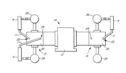
Figure 1 is a schematical representation of a
reciprocating compressor system to which the method and
apparatus of the present invention are applied and
showing apparatus for use in carrying out the method
according to the invention in place on the compressor
system;
Figure 2 is a schematical illustration showing a
longitudinal section through a cylinder block of a
compressor unit in the compressor system of Figure l;
Figure 3 is a view similar to that of Figure 2
but showing an alternative embodiment of the invention
wherein the testing apparatus is built into the compressor
unit;
Figure 4 is a cross section along the lines
IV-IV in Figure 3; and
Figure 5 is a longitudinal section, on a larger
scale, of the built-in test apparatus.
The apparatus used in carrying out the method
according to one aspect of the invention comprises a high
pressure flowmeter 9 and high pressure hoses 11 provided
with "Kiene" connectors for connection to the head end and
2n~0~
crank end indicator cocks which are conventionally
provided on reciprocating compressor units. These hoses
11 and the flowmeter 9 are selected so that they are
suitable for the highest pressures encountered in a
compressor system, typically up to 1000 psig. Flow rates
for healthy machines are expected to be low, i.e. in the
region of 100 SCFH.
With reference to Figure 1, a compressor system
is generally indicated at 10. The compressor system 10
comprises a main frame 12, connected to a plurality of
compressor units, two of which are shown and generally
indicated at 13 in Figure 1. Although only two
compressor units 13 are shown, it will be appreciated
that any suitable number of compressor units 13 may be
provided, as desired. For example, a plurality of
compressor units 13 being employed in successive stages of
compression may be employed, the discharge pressure of one
stage representing the suction pressure of a next stage,
etc.
A single compressor unit 13 is shown in
Figure 2. It comprises a cylinder block 20 which houses a
piston 16 which is mounted for reciprocating movement in a
cylinder 18. The main frame 12 (Figure 1) houses a
crankshaft 14 (Figure 2) for driving the respective
pistons 16 of the compressor units 13. Each piston 16 is
provided with rings 17 to seal the gap between the piston
16 and the inner wall of its respective cylinder 18. Each
cylinder block 20 has a standard Kiene head end indicator
cock 22 and a crank end indicator cock 24. Each
compressor unit 13 also has a suction bottle 26 and a
discharge bottle 28.
In the remainder of this description reference
will only be made to the single compressor unit 13, shown
- 6 - 2040~
in Figure 2, it being understood that the description
applies equally to all the other compressor units 13
present in the compressor system 10.
A pair of suction valves 30 and 31 are provided
on the suction side of the cylinder 18, the valve 30 being
a head end suction valve and the valve 31 being a crank
end suction valve. A head end discharge valve 32 and a
crank end discharge valve 33 are, likewise, also provided.
The suction and discharge valves 30 to 33 are check valves
which only allow fluid to flow through them in the
directions indicated by the arrows in Figure 2.
The suction bottle 26 is connected to the head
end and crank end suction valves 30, 31 through a suction
manifold 34 and the discharge bottle 28 is connected to
the head end and crank end discharge valves 32, 33 by
means of a discharge manifold 36.
The piston 16 has a piston rod 38 which is
connected to a crosshead 40 which is movable between
guides 42 and connected to the crankshaft 14 by means of a
connecting rod 44. Rod packing 3g is provided to provide
a seal between the piston rod 38 and the cylinder block
20. When the crankshaft 14 is rotated, a reciprocating
motion is imparted to the piston 16 in the cylinder 18 to
pump fluid, such as air, from the suction side to the
discharge side of the cylinder 18, thus to effect
compression of the fluid.
The condition of a compressor unit 13 is largely
reflected by the condition of the seal between the piston
16 and the cylinder inner wall, which is provided by the
piston rings 17, as well as the condition of the suction
and discharge valves 30 to 33.
- 7 - 20 40~6 ~
To test the conditions of the above-mentioned
parts, the invention provides that tests are carried out
for fluid leakage past the piston rings 17, as well as for
leakage of the suction and discharge valves 30 to 33.
To effect these tests, the compressor system 10
is stopped. In this condition, the suction bottle 26 and
the suction manifold 34 will be at a suction pressure (Ps)
of, say, about 300 psig, and the discharge bottle 28 and
the discharge manifold 36 will be at a discharge pressure
(Pd) of, say, about 1000 psig.
The tests are carried out in six steps which
test for leakage of each of the four valves 30 to 33, as
well as for piston ring leakage in both directions across
the piston 16. In carrying out the tests, two flowmeters
9 and two sets of hoses 11 are conveniently used for the
tests Nos. 3 to 6.
Test No. 1: Head End Discharge Valve Condition
In this test the head end of the cylinder 18 is
vented to the suction bottle 26 by connecting the
flowmeter 9 with the hoses 11 between the head end
indicator cock 22 and the suction bottle 26. This
connection is shown on the right hand side of Figure 1.
Thus, the head end will be at a pressure of Ps~ as shown
in Figure 2. If there is no leakage through the head end
discharge valve 32, there will be no fluid flow detected
by the flowmeter 9, after an initial period during which
the pressures between the cylinder head end and the
suction bottle are equalized. However, if there is
leakage back through the valve 32 from the cylinder
discharge manifold (which is at a pressure of Pd) and the
head end which is at the lower suction pressure (Ps)~ then
2~40067
the flowmeter 9 will detect a fluid flow, indicating that
the valve 32 is leaking.
Test No. 2: Crank End Discharqe Valve Condition
In this test, the cylinder crank end is vented
to the suction bottle 26 by connecting the flowmeter 9
with the hoses 11, between the crank end indicator cock 24
and the bottle 26. Any flow of fluid which is measured
after an initial pressure equalization period, will be an
indication of leakage through the crank end discharge
valve 33.
Test No. 3: Piston Ring Leakage from Head End
For this test the cylinder head end is
pressurized with Pd by connecting the discharge bottle 28
to the head end through the hoses 11 and one of the
flowmeters 9. The cylinder crank end is then vented to
the suction bottle 26 by connecting the second flowmeter g
with hoses 11 between the crank end indicator cock 24 and
the suction bottle 26. After an initial time to allow
for the equalization of pressures, any flow measured by
the second flowmeter 9 will be an indication of piston
ring leakage from the head end to the crank end of the
cylinder 18.
Test No. 4: Piston Ring Leakaqe from Crank End
For this test the crank end is pressurized with
Pd by connecting the discharge bottle 28 to the crank end
through the one flowmeter 9 and hoses 11 and the head end
is then vented to the suction bottle 26 by connecting the
second flowmeter 9 with the hoses 11 between the head end
indicator cock 22 and the suction bottle 26. These
connections are shown on the left hand side of Figure 1.
9 2~a~
Any flow measurement by the second flowmeter 9 will be an
indication of piston ring leakage from the crank end to
the head end of the cylinder 18.
Test No. 5: Head End Suction Valve Condition
For this test, the cylinder head end is
pressurized with Pd by connecting the discharge bottle 28
to the head end through the one flowmeter 9 and hoses 11.
The suction bottle 26 is then vented to a lower stage
suction or to atmosphere, i.e. to a pressure below Ps~
through the second flowmeter 9 and hoses 11. Any flow
measurement by the second flowmeter 9 will be an
indication of leakage by the head end suction valve 30.
Test No. 6: Crank End Suction Valve Condition
For this test, the crank end is pressurized with
Pd by connecting the discharge bottle 28 to the crank end
through the one flowmeter 9 and hoses 11. The suction
bottle 26 is then vented to a lower stage suction or to
atmosphere through the second flowmeter 9 and hoses 11.
Any flow detected by the second flowmeter 9 will be an
indication of leakage by the crank end suction valve 31.
By way of example, if flow rate measurements of
50, 40, 110, 120, 30 and 20 SCFN were obtained during the
above-mentioned tests 1 to 6 respectively, this would
indicate excessive leakage of the piston rings 17 in both
directions.
In the tests Nos. 3 to 6 above, the purpose of
the first flowmeter 9 is simply to test for equalization
of pressure and it is not essential for carrying out the
tests.
2040067
-- 10 --
It will be appreciated that, in true life
situations, the suction and discharge valves 30 to 33 each
comprises a plurality of separate valves arranged in a
circular configuration. Thus, an ultrasonic detector
(not shown) may be used during the above tests to
determine which of the several valves is responsible for
the leakage. The rod packing 39 can be checked for
leakage by flow rates forced out of the crosshead
compartment (see below) or by ultrasonics.
In an alternative embodiment of the invention,
the apparatus for carrying out the tests 1 to 6 above is
built into a compressor unit, thus avoiding the use of
external flowmeters and hoses. Such a compressor unit is
shown at 50 in Figures 3 and 4. Parts of the unit 50
which are similar to the unit 13 are indicated by like
reference numerals.
As shown in Figures 3 and 4, an extra port 52 is
provided to house a built-in test apparatus 54. Four such
test apparatuses 54 are provided for each cylinder 18,
i.e. head end suction and discharge and crank end suction
and discharge.
The test apparatus 54 is shown on a larger scale
and in more detail in Figure 5. In this drawing reference
numeral 46 denotes the outer casting and reference numeral
48 the inner casting of the compressor cylinder 18. The
cylinder bore is indicated at 50. Reference numeral 51
indicates the gas passage between the inner and outer
castings 45, 48.
The test apparatus 54 comprises a cylindrical
body member 56 provided with a central bore 58 in which a
valve stem 60 is located. A head portion 62 is provided
at the upper end of the body member 56. The head
2040~7
-- 11 --
portion 62 houses a diaphragm 64 and is provided with a
pressure inlet port 68. A valve 70 is provided at the
lower end of the stem 60. The valve 70 cooperates with a
valve seat 72 to open and close the valve. The valve 70
is biased to a closed position by means of a spring 74. A
connecting passage 76 is provided at the lower end of the
body member 56 so that, when the valve 70 is open, fluid
flow between the cylinder bore 50 and a chamber 78 in the
lower portion of the body member 56 is possible.
A sealing gasket 66 is located at the lower end
of the body member 56. Reference numerals 81 and 83 refer
to O-rings for producing seals between the body member 56
and the outer casting 46 and the stem 60 and the body
member 56, respectively.
An orifice 80 is provided in the chamber 78, and
a pair of ports 82 and 84 are provided. The one port 82
is connected to the chamber 78 at a location below the
orifice 80 and the port 84 is connected to the chamber 78
at a location above the orifice 80. A vent 85 is provided
between the chamber 78 and the cylinder passages external
to the cylinder bore 50. Depending on where the test
apparatus 54 is located, the cylinder passages referred to
above can be the passages in the suction manifold 34 or
the passages in the discharge manifold 36.
OPERATION
In operation, the test apparatus 54 is activated
by applying a pressure, such as 100 psi, to the inlet port
68. This urges the diaphragm 64 downwards and opens the
valve 70. A fluid flow passage between the interior and
the exterior of the cylinder bore 50 through the orifice
80 is, therefore, opened. By applying a pressure
differential meter (not shown) between the ports 82 and
2040~7
- 12 -
84, the pressure differential caused by any fluid flow
through the orifice 80 can be obtained. This allows
calculation of fluid flow across the orifice and thus,
fluid flow between the interior and the exterior of the
cylinder bore 50. This built-in apparatus, therefore,
takes the place of the flowmeter 9 and hoses 11 used in
the external apparatus.
To carry out Test No. 1, referred to above, the
test apparatus 54, located in the head end suction side,
is employed. By activating this test apparatus, the head
end of the cylinder is vented to the suction bottle 26
through the vent 85.
To carry out Test No. 2, the crank end suction
test apparatus will be activated.
To carry out Test No. 3, both the head end
discharge test apparatus and the crank end suction test
apparatus will be activated. This will result in the
cylinder head end being pressurized to Pd and the crank
end being vented to the suction bottle 26.
To carry out Test No. 4, the crank end discharge
test apparatus and the head end suction test apparatus are
employed.
Finally, to carry out Tests Nos. 5 and 6, the
head end discharge and crank end discharge test
apparatuses are activated.
While only preferred embodiments of the
invention have been described herein in detail, the
invention is not limited thereby and modifications can be
made within the scope of the attached claims.