Note: Descriptions are shown in the official language in which they were submitted.
2040 1 49
WOBBLE PLATE TYPE COMPRESSOR
BACKGROUND OF THE INVENTION
I. Teçhni~al Field
The present invention relates to a refrigerant compressor, and
more particularly, to a wobble plate type compressor for use in an
automotive air conditioning system.
of the Prior Art
Figure 1 illustrates a general construction of a wobble plate
type refrigerant compressor with a variable displacement meçh~nicm
for use in an automotive air conditioning system. With reference to
Figure 1, compressor 10 includes cylindrical holl.cin~ ~ccembly 20
including cylinder block 21, front end plate 23 at one end of cylinder
block 21, crank çh~mber 22 formed between cylinder block 21 and
front end plate 23, and rear end plate 24 attached to the other end of
cylinder block 21. Front end plate 23 is mounted on cylinder block 21
forward (to the left in Figure 1) of crank chamber 22 by a plurality of
bolts 101. Rear end plate 24 is mounted on cylinder block 21 at its
opposite end by a plurality of bolts 102. Valve plate 25 is located
between rear end plate 24 and cylinder block 21. Opening 231 is cen-
trally formed in front end plate 23 for supporting drive shaft 26 by
bearing 30 tlicp~ed in the opening. The inner end portion of drive
shaft 26 is rotatably supported by bearing 31 disposed within central
=~
2040 1 49
bore 210 of cylinder block 21. Bore 210 extends to a rearward end
surface of cylinder block 21 to dispose valve control mech~ni.sm 19
which comprises crank pressure r~on~ive bellows 193 and discharge
pressure responsive rod 195. Valve control mech~ni~m 19 controls the
opening and closing of communication path 150, which is formed in
cylinder block 21 and later-mentioned valve plate ~c~embly 200 in
order to provide communication between crank rh~ml~r 22 and suc-
tion ch~mher 241. Further details of valve control mechani.cm 19 and
the component parts associated therewith are disclosed in U.S. Patent
No. 4,960,367 to Terauchi, a detailed explanation thereof is therefore
omitted.
Cam rotor 40 is fixed on drive shaft 26 by pin member 261 and
rotates with drive shaft 26. Thrust needle bearing 32 is ~ p~sed
between the inner end surface of front end plate 23 and the adjacent
axial end surface of cam rotor 40. Cam rotor 40 includes arm 41 hav-
ing pin memher 42 exten~ing therefrom. Slant plate 50 is adjacent
cam rotor 40 and includes opening 53 through which passes drive shaft
26. Slant plate 50 includes arm 51 having slot 52. Cam rotor 40 and
slant plate 50 are connected by pin member 42, which is inserted in
slot 52 to create a hinged joint. Pin member 42 is slid~hle within slot
52 to allow adjustment of the angular position of slant plate 50 with
respect to the longitudinal axis of drive shaft 26.
Wobble plate 60 is rotatably mounted on slant plate 50 through
bearings 61 and 62. Rotation preventing device 610 includes
fork-shaped slider 611 attached to the outer peripheral end of wobble
plate 60 and sliding rail 612 which is held between front end plate 23
-- 3 --
20401 49
and cylinder block 21. Fork-shaped slider 611 is slidably mounted on
sliding rail 612. Rotation preventing device 610 prevents rotation of
wobble plate 60, thereby allowing wobble plate 60 to nutate when cam
rotor 40 rotates. Further details of rotation preventing device 610 are
disclosed in U.S.Patent No. 4,875,834 to Higuchi et al., therefore, a
detailed explanation thereof is omitted.
Cylinder block 21 includes a plurality of (for example, seven)
identical axial cylinders 70 formed therein, in which identical pistons
71 are slidably and closely fitted. Each piston 71 is connected to wob-
ble plate 60 through piston rod 72. Ball 72a at one end of rod 72 is
firmly received in socket 711 of piston 71 by caulking an edge of
socket 711, and ball 72b at the other end of rod 72 is firmly received
in socket 601 of wobble plate 60 by caulking an edge of socket 601.
But, balls 72a and 72b are slic~ e along an inner spherical surface of
sockets 711 and 601 respectively. The center of the ball-and-socket
joint of piston 71 is located on the longitudinal axis of cylinder 70. It
should be understood that, although only one ball-and-socket joint is
illustrated in the drawing, there are a plurality of sockets peripherally
arranged around wobble plate 60 to receive the balls of various rods
72, and that each piston 71 is formed with a socket for receiving the
other balls of rods 72.
Rear end plate 24 includes peripherally located ~nn~ r suction
chamber 241 and centrally located discharge ch~ml~er 251. Valve
plate 25 is located between cylinder block 21 and rear end plate 24
and includes a plurality of valved suction ports 242 linking suction
chamber 241 with respective cylinders 70. Valve plate 25 also
~4 2040 1 ~9
includes a plurality of valved discharge ports 252 linking rlicch~rge
ch~mher 251 with respective cylinders 70. In order to maintain an
effective seal between cylinder block 21 and valve plate 25, suction
ports 242 and discharge ports 252 are provided with suitable reed
valves, as described in detail in U.S. Patent No. 4,011,029 to Shimi7u.
Suction ch~mh~r 241 further includes inlet portion 241a which
is connected to an evaporator (not shown) of an external cooling cir-
cuit. Discharge chamber 251 is provided with outlet portion 251a
connected to a con~lenser (not shown) of the cooling circuit. Gaskets
27 and 28 are located between cylinder block 21 and the inner sur-
faces of valve plate 25 and rear end plate 24, respectively, to thereby
seal the mating surfaces of cylinder block 21, valve plate 25 and rear
end plate 24. Gaskets 27 and 28 and valve plate 25 thus form valve
plate ~c~cemhly 200.
Figure 2 s~hematically illustrates a vertical transverse sec-
tional view of a wobble plate type refrigerant compressor in accor-
dance with one embodiment of the prior art, like numerals denoting
co~ on.ling Plements to those shown in Figure 1. The locational
relationchip between the ball-and-socket joints provided at wobble
plate 60 and the ball-and-socket joints provided at each of respective
pistons 71 is specifically illustrated.
With reference to Figure 2, points P'1-P'7 represent the center
of the ball-and-socket joints of seven identical pistons 71, respec-
tively, and points W~l-W~7 represent the center of the ball-and-socket
joints of wobble plate 60, respectively.
2040 1 49
A plurality of (for example, seven) cylinders 70 are periph-
erally located in cylinder block 21 about the longitudinal axis of drive
shaft 26 with an equiangular interval. Therefore, points P'l-P'7 are
peripherally located about the longitudinal axis of drive shaft 26 with
an e~ ngular interval. Similarly, points W'l-W'7 are peripherally
located about the longitudinal axis of wobble plate 60 with an equian-
gular interval. Points W'l-W'7 are located on first circle C'l, and
points P'l-P'7 are located on second circle C'2.
Figure 2 specifically illustrates a situation in which a plane
surface including first circle C'l is positioned so as to be parallel with
a plane surface including second circle C'2. Therefore, first and sec-
ond circles C'1 and C'2 are concentric with respect to a point "O"
through which the longitudinal axes of both drive shaft 26 and wobble
plate 60 pass. As illustrated, the radius of circle C'l is greater than
the radius of circle C'2.
ln the ~ccemhling process of the compressor, points W'l-W'7 are
positioned so as to be radially aligned with points P'l-P'7, respec-
tively, when fork-shaped slider 611 is mounted on sliding rail 612. As
illustrated in Figure 2, a center axis passes through point "O", the
radially aligned points W'l and P'l, and the center of rotation preven-
tion means 610 which is aligned therewith.
In general, if an ideal rotation preventing device is utilized in
the compressor, the wobble plate nutates with uniform angular veloc-
ity about the longitudinal axis thereof when a cam rotor rotates.
Therefore, when a cam rotor rotates, every location of the wobble
plate simultaneously traces both an axially elongated figure eight if
_ - 6 - 2 ~ 4 0 1 4 ~
viewed in the radial direction and a circular figure if viewed in the
axial direction.
However, when the compressor illustrated in Figure 2 operates,
wc~ ~ plate 60 nutates with a non-uniform angular velocity about the
longitudinal axis thereof when cam rotor 40 rotates. Rec~ se rotation
preventing device 610 is less than ideal, it does not allow wobble plate
60 to nutate with uniform angular velocity about the longitudinal axis
thereof. Therefore, wobble plate 60 nutates with an angular accelera-
tion. Accordingly, there is a torque acting on wobble plate 60 which
tends to rotate it in the rotational direction ~'A~ of cam rotor 40. The
torque is the product of the angular acceleration and the moment of
inertia of wobble plate 60 when cam rotor 40 rotates. Therefore, the
value of the torque cyclically varies with the rotation of cam rotor 40
as shown by the graphical representation in Figure 8. In the graph,
the period of the cycle is given by the fraction 2~/~. The denomina-
tor of the fraction 2~r/7 is the nllmhPr of cylinders ~0 in the compres-
sor. When the differential "H" between the maximum and minimum
values of the torque exceeds a certain value, a backlash between
slider 611 and rail 612 is thereby created. Therefore, collisions
between one inner plane side surface 611a of slider 611 and one outer
plane side surface 612a of rail 612, and the other inner plane side sur-
face 611b of slider 611 and the other outer plane side surface 612b of
rail 612 are cyclically repeated when cam rotor 40 rotates. This
cyclic collision impacts upon wobble plate 60 and rotation preventing
device 610, thereby causing damage thereto. Furthermore, the cyclic
c~lli.cion generates a cyclic contact noise which is conducted to a
- 7 - 2 0 4 0 1 4 9
r~-csencer compartment of an automobile and thereby produces an
offensive noise to the p~csenge.s.
Figure 3 schem~tically illustrates a trars~/e-se vertical sec-
tional view of a wobble plate type refrigerant compressor in accor-
dance with another emho~liment of the prior art, lh~ce numerals repre-
senting corresponding elements to those shown in Figure 1. In the
drawing, a locational relationship between the ball-and-socket joints
provided at wobble plate 60 and the ball-and-socket joints provided at
each of respective pistons 71 is specifically illustrated.
In this prior art embodiment, a plurality of (for Px~mple,
seven) identical axial cylinders 701-707 are peripherally located about
the longitudinal axis of drive shaf t 26. The longitudinal axes of
respective cylinders 701-707 are represented by points P'11-P'17
which are located at the center of the ball-and-socket joints of identi-
cal seven pistons 711-717, respectively. Points W'11-W'17 are periph-
erally located about the longitudinal axis of wobble plate 60 with an
equiangular interval, as in the prior art embodiment of Figure 2.
Points W~ll-W~17 are located at the center of the respective ball-and-
socket joints of wobble plate 60, and are located on first circle Cl.
Points P'll-P'17 are located on second circle C'2. Point P'14, point
P~15, and point ''O'l through which the longitudinal axis of cam rotor
40 p~Cses~ define a small sector and a rem~ining larger sector. The
larger sector is equally divided into six identical sectors having arcs
P'l1 to P'12. P'12 to P'13, P'13 to P'14, P~ls to P'16, P'16 to P~17, and
P'17 to P'll, respectively. The arc length, and thus the corresponding
angle, of the small sector is designed to be slightly greater than the
2040 ~ 4~
arc of each of the six identical sectors in order to provide adequate
space for sliding rail 612 of rotation preventing device 610 to be
located between pistons 714 and 715.
Figure 3 specifically illustrates a situation in which a plane
surface incl~l~ling first circle Cl is positioned so as to be parallel with
a plane surface including second circle C'2, as in the embodiment of
Figure 2. Therefore, first and second circles C1 and C'2 are concen-
tric with respect to point "O" through which the longitudinal axes of
both cam rotor 40 and wobble plate 60 pass. As illustrated the radius
of circle C1 is greater than the radius of circle C'2.
In the ~csemblinE process of the compressor, point Wl11 is posi-
tioned so as to be radially aligned with points P'11 when fork-shaped
slider 611 is mounted on sliding rail 612. Accordingly, points P'12-P'14
are symmetrical with points P'l~l-P'15, respectively, with respect to
the line which passes through points "O", P'l1 and Wlll. Therefore,
the angular position of points W1l2-W~l4 about point IIOII are shifted in
the rotational direction "A" of cam rotor 40 with respect to points
P'12-P'14, respectively; and the angular position of points W'17-Wt15
about point ~O~ are shifted in the opposite rotational direction of cam
rotor 40 with respect to points P'17-P'1s, respectively. The amount of
angular shift of respective points W'12-W1l4 about point "O" from
respective points P'12-P'14 in the rotational direction ~A" of cam
rotor 40 is gradually increased from point w~12 to point W~14. The
amount of angular shift of respective points Wll~-WTl5 about point
'IO~I from respective points P~17-P~ls in the opposite rotational
20~0 1 49
direction of cam rotor 40 is gradually increased from point W~17 to
point W1l5.
When the compressor illustrated in Figure 3 operates, wobble
plate 60 behaves in the same m~nner as described in the prior art
embo~im~nt of Figure 2, lller~b~ c~ ng the same defects as
described therefor.
8UMMARY OF THE lN V ~ ON
Accordingly, it is an object of an aspect of the
present invention to provide a wobble plate type
compressor in which rotation of a wobble plate is
prevented without generating a cyclic collision between
a fork-shaped slider and a sliding rail of a rotation
preventing device of the wobble plate.
A wobble plate type compressor embodying the
invention comprises a housing having a
cylinder block provided with a plurality of cylinders and a crank
ch~mh~r adjacent the cylinder block. A piston is slidably fitted
within each of the cylinders. A drive shaft is rotatably sup~r~ed in
the hollsing. A rotor is fixed on the drive shaft and further connected
to an inclined plate, such as a slant plate. A wobble plate is rli~d
on an inclined surface of the slant plate.
A coupling member, such a~s a connecting rod collple-s the wo~
ble plate with each of the plurality of pistons. The connecting rod
ncludes one ball-shaped end which is coul~led with the wobble plate
by a ball-and socket pint and another ball-~sh~recl end which is cou-
pled with each of the piston~s by a ball-an-l socket joint. Rotational
motion of the slant plate is converted into nutational motion of the
wobble plate by mean~s of a rotation preventing device which prevents
- 10 - 2040l49
rotation of the wobble plate when the rotor rotates. The rotation
preventing device includes a sliding rail axially exten~ g within the
crank ~h~mher and a fork-shaped slider attached to an outer periph-
eral end of the wobble plate and slidably mounted on the sliding rail.
The centers of one of the ball-shaped ends of the plurality of
connecting rods are radially shifted by a predetermined angle in the
rotational direction of the cam rotor with respect to the centers of
the other ball-shaped ends of the plurality of connecting rods.
Other aspects of this invention are as follows:
In a wobble plate type compressor comprising a compres-
sor housing having a cylinder block provided with a plurality of cylin-
ders and a crank ch~mber enclosed within said cylinder block, a piston
slidably fitted within each of said cylinders, a drive shaft rotatably
supported in said hollcing, a rotor fixed on said drive shaft and further
connected to an inclined plate, a wobble plate rotatably mounted on
said inclined plate, a coupling member for coupling said wobble plate
with each of said plurality of pistons, said coupling member having one
end which is coupled with said wobble plate and another end which is
co~pled with each of said pistons, and rotation preventing means for
preventing rotation of said wobble plate such that rotational motion of
said inclined plate is converted into nutational motion of said wobble
plate, said rotation preventing means in~lu~ling a guide member axially
ext~n~ling within said crank rh~mh~r and a fork-shaped member
slidably mounted on said g`uide, said fork-shaped memb~r attached to an
outer peripheral end of said wobble plate, the improvement comprising:
said one end of said co~pling memb~r is radially shifted in the
rotational direction of said rotor with respect to said other end of said
co~pling member, by a predetermined angle.
-
- lOa - 20401 49
A wobble plate type compressor comprising:
a compr~or h~ Cing;
a cylinder block defined within said compressor hol~cing;
said cylinder block in~ J-~inC a plurality of cylinders;
a crank ~h~mher enclosed within said cylinder block;
a piston slidably fitted within each of said cylinders;
a drive shaft rotatably supported in said housing;
a rotor fixed on said drive shaft;
an inclined plate connected to said rotor;
a wobble plate rotatably mounted on said inclined plate;
a coupling member for coupling said wobble plate with each of
said pistons;
said coupling member having one end which is coupled to said
wobble plate and another end which is coupled to each of said pistons;
rotation preventing means for preventing rotation of said wobble
plate such that the rotational motion of said inclined plate is converted
into nutational motion of said wobble plate; and
said rotation preventing means including a guide member axially
exten~ling within said crank ~h~mber and a fork-shaped member
slidably mounted on said guide member, said fork-shaped member
attached to an outer peripheral end of said wobble plate;
wherein one of said ends of said coupling member is radially
shifted by a predetermined angle in the rotational direction of said
rotor, with respect to said other end of said coupling member.
- 10b - 2 0 ~ O 1 ~ 9
A wobble plate type compressor comprising:
a compressor holl.cing;
a cylinder block defined within said compressor hol~sing;
said cylinder block including a plurality of cylinders;
a crank rh~mber enclosed within said cylinder block;
a piston slidably fitted within each of said cylinders;
a drive shaft rotatably supported in said hollcing;
a rotor fixed on said drive shaft and further connected to an
inclined plate;
a wobble plate rotatably mounted on said inclined plate;
a couFIi~ member for coupling said wobble plate with each of
said plurality of p~lons;
said collpling m~mber having one end which is coupled to said
wobble plate and another end which is coupled to each of said plurality
of pislor~;
rotation preventing means for preventing rotation of said wobble
plate such that rotational motion of said inclined plate is converted
into nutational motion of said wobble plate; and
said rotation preventing means incluAing a sliding rail guide
member axially extenAing within said crank ch~mber and a fork-shaped
slider member slidably mounted on said guide member, said fork-shaped
member attached to an outer peripheral end of said wobble plate;
a center axis having a centerpoint which intersects the longitu-
dinal axis of said driveshaft, said center axis defined when an axis is
passed through the centers of said end of said coupling membf~r that is
coupled to said wobble plate and said end of said coupling member
- loc - 2 0 4 0 ~ 4 9
which is coupled to one of said plurality of pistons, when the centers
are radially aligned, and through the center of said rotation prevention
means when it is aligned in a vertical plane therewith; and
wherein said sliding rail guide is radially shifted with respect to
said center axis of said compressor by a predetermined angle in the
direction of the rotation of said rotor, such that the center of said end
of said coupling member that is coupled to said wobble plate is radially
shifted in the direction of rotation of said rotor with respect to the
center of said end of said co~lrlinE member which is colJpled to one of
said pistons.
A wobble plate type compressor comprising:
a compressor hollcing;
a cylinder block defined within said compr~sor hollcing;
said cylinder block including a plurality of cylinders;
a crank ch~mher enclosed within said cylinder block;
a piston slidably fitted within each of said cylinders;
a drive shaft rotatably supported in said hollcin~;
a rotor fixed on said drive shaft and further connected to an
inclined plate;
a wobble plate rotatably mounted on said inclined plate;
a couplina member for co~pling said wobble plate with each of
said plurality of pistons;
said collt~ g member having one end which is coupled to said
wobble plate and another end which is coupled to each of said plurality
of pistons;
rotation preventing means for preventing rotation of said wobble
plate such that rotational motion of said inclined plate is converted
into nutational motion of said wobble plate; and
- - `
2040 1 49
said rotation preventing means including a sliding rail guide
member axially extending within said crank ch~mber and a fork-shaped
slider member slidably mounted on said guide member, said fork-shaped
member attached to an outer peripheral end of said wobble plate;
a center axis having a centerpoint which intersects the longitu-
dinal axis of said driveshaft, said center axis defined when an axis is
passed through the centers of said end of said collrline member that is
coupled to said wobble plate and said end of said coupling member
which is coupled to one of said plurality of pistons, when the centers
are radially aligned, and through the center of said rotation prevention
means when it is aligned in a vertical plane therewith; and
wherein said fork-shaped slider memhpr is radially shifted with
respect to said center axis of said compr~sor by a predetermined angle
in a direction opposite to the rotational direction of said rotor.
BRIEF DESCRIPTION OF THE DRAWINGS
Figure 1 illustrates a vertical longitudinal sectional view of a
wobble plate type refrigerant compr~r with a variable displace-
ment mech~ni-cm in accordance with the prior art.
Figure 2 schem~tically illustrates a vertical transverse. sec-
tional view of a wobble plate type refrigerant compr~or in acco~
dance with one prior art embodiment. In the drawing, a locational
relationship between the ball-and socket joints provided at a wobble
plate and the ball-and~ocket pints provided at each of the respective
pistons is specifically illustrated.
r~'~ .
- lOe - 20401 49
Figure 3 schem~tically illustrates a vertical tran~ve,se sec-
tional view of a wobble plate type refrigerant compre:~r in accor-
dance with another prior art embodiment. In the drawing, a
locational relationship between the ball-and-socket pints provided at
a wobble plate and the ball-and-socket joints provid(ed at each of the
respective pistons is specifically illustrated.
Figure 4 schem~tically illustrates a vertical transverse sec-
tional view of a wobble plate type ref rigerant com~re~sor in
.~ ~,,
2Q401 49
accordance with a first em~im~nt of the present invention. In the
drawing, a locational relationship between the ball-and-socket joints
provided at a wobble plate and the ball-and-socket pints provided at
each of the respective pistons is specifically illustrated.
Figure 5 illustrates a dynamic schem~tic of the present
invention.
Figure 6 schem~tically illustrates a vertical transverse sec-
tional view of a wobble plate type refrigerant compressor in accor-
dance with a second embodiment of the present invention. In the
drawing, a locational relationship between the ball-and~ocket joints
provided at a wobble plate and the ball-and~ocket joints provided at
each of the respective pistons is specifically illustrated.
Figure 7 schem~tically illustrates a vertical transverse sec-
tional view of a wobble plate type refrigerant compressor in accor-
dance with a third embo~liment of the present invention. In the draw-
ing, a locational relationship between the ball-and~ocket joints pro-
vided at a wobble plate and the ball-and-socket joints provided at
each of the respective pistons is specifically illustrated.
Figure 8 is a graphical representation of the variance in the
torque acting upon a wobble plate which occurs during the rotation of
a cam rotor in a wobble plate type refrigerant compressor.
DETAILED DESCRIPTION OF THE pREF~RR~n EMBODIMENTS
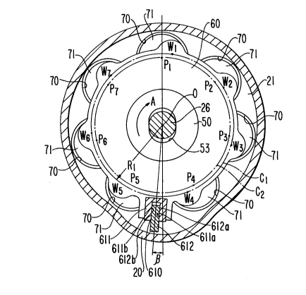
With reference to Figure 4, a first embodiment of the present
invention is applied to the prior art embodiment of Figure 2, with like
numerals representing corresponding elements as shown in Figures 1
and 2. Points Pl-P7 represent the centers of the ball-and-socket
- 12 -
20 4 0 1 ~9
joints of seven identical pistons 71, respectively, and points Wl-W7
represent the centers of each of the ball-and-socket pints of wobble
plate 60, respectively.
A plurality of (for example, seven) cylinders 70 are periph-
erally located about the longitudinal axis of drive shaft 26 with an
equiangular interval, as described for Figure 2. Therefore, points Pl-
P7 are peripherally located about the longitudinal axis of drive shaft
26 with an equiangular interval. Furthermore, points Wl-W7 are
peripherally located about the longitudinal axis of wobble plate 60
with an equiangular interval, as in the prior art embodiment shown in
Figure 2. Points Wl-W7 are located on first circle Cl and points Pl-
P7 are located on second circle C2.
Figure 4 specifically illustrates a situation in which a plane
surface inclu-ling first circle Cl is positioned so as to be parallel with
a plane surface inclu~ffnE second circle C2, as was the case in Figure
2.
However, in the first embodiment of the present invention,
sliding rail 612 is positioned so as to be radially shifted by angle B in
the rotational direction "A" of cam rotor 40 with respect to the loca-
tion at which sliding rail 612 was positioned in the prior art embodi-
ment of Figure 2. That is, sliding rail 612 is radially shifted with
respect to the center axis p~sing through radially aligned points W'l
and P~1 and the center of rotation prevention means 610 when it iS
aligned therewith, as shown in Figure 2. Therefore, in the ~cemhlinE
process of the compressor, points Wl-W7 are radially shifted in the
rotational direction ~A~ of cam rotor 40 with respect to points P1-P7,
_ - 13--
20401 ~9
respectively, by an angle B, (for e~r~mple~ ~r /60) when fork~haped
slider 611 is mounted on sliding rail 612. As a result, when the com-
pressor operates, a torque which tends to rotate wobble plate 60 in
rotational direction ~A~ of cam rotor 40 is generated.
A dynamic analysis with respect to the first embo~liment of the
present invention is described below. With reference to Figure 5,
force Ft is a component force of gas pressure reaction force Fp which
acts on piston 71. Component force Ft, as given by equation (1), acts
on point Wi along the tangent at point Wi on first circle C1.
Ft = (Fp)(tan ) (1)
In equation (1), angle a (alpha) is the angle between the line
including points P'i and W~i and the line inClu-ling points Pi and Wi.
Since a~ is small, tan can be approximately substituted for by
(Rl)(B)/(L). In this term, "R1" is the radius of first circle Cl. Angle B
is the angle between the line including points "O" through which the
longitudinal axis of wobble plate 60 passes and W'i, and the line
including points "O" and Wi. ~L~' is the distance between points Pi and
W~i, that is, P'i and W~i. Therefore, equation (1) is transformed into
equation (2).
Ft = (Fp)(Rl)(B)/ L (2)
Accordingly, the torque T which tends to rotate wobble plate 6û
in rotational direction ~A~ of cam rotor 40 in shown by equation (3).
T = (Ft)(Rl)
- 14 - 2 0 4 0 1 4 9
By using equation (2), equation (3) is transformed into equation
(4).
T = (Fp)(R 12)( B)/ L (4)
In this embo~liment~ by appropriately specifying angle B, the
magnitude of torque T can be designed to maintain one inner plane side
surface 611a of slider 611 in contact with one outer plane side surface
612a of rail 612 when cam rotor 40 rotates even though differential ~H"
exceeds the certain value, as discussed above with reference to Figure
8. Therefore, the cyclic collision between slider 611 and rail 612 can
be elimin~ted, thereby preventing damage to wobble plate 60 and
rotation preventing device 610 and eliminating the offensive cyclic
contact noise between slider 611 and rail 612.
Figure 6 schematically illustrates a vertical transverse sectional
view of a wobble plate type refrigerant compressor in accordance with
the present invention, as applied to the prior art embodiment of Figure
3, with like numerals representing corresponding elements as shown in
Figures 1 and 3. In the drawing, the locational relationship between
the equiangular ball-and-socket joints provided at wobble plate 60 and
the non-equiangular ball-and-socket joints provided at each of respec-
tive pistons 711-717 is specifically illustrated. In the locational rela-
tionship between the ball-and-socket joints provided at wobble plate 60
and the ball-and-socket joints provided at each of respective pistons
711-717, this second embodiment is similar to the prior art embodiment
of Figure 3, with the exception of the following matter.
In the second embodiment of the present invention, sliding rail
612 is positioned so as to be radially shifted by angle B in the rotational
- 15 -
2Q401 49
direction "A" of cam rotor 40, with respect to the location at which
sliding rail 612 was positioned in the prior art Pmbolliments. There-
fore, in the ~ccemhling process of the compressor, points Wll-W17 are
radially shifted in the rotational direction "A" of cam rotor 40 with
respect to points Pll-P17, respectively, by angle B (for PY~mrle~ ~r/60)
when fork-shaped slider 611 is mounted on sliding rail 612. The effect
of this embodiment is similar to the effect of the first emho~iment~ and
therefore a detailed Pxpl~n~tion thereof is omitted.
In the first and second embodiments of the present invention,
sliding rail 612 ic positioned so as to be radially shif ted in the rotational
direction "A" of cam rotor 40, with respect to the location at which
sliding rail 612 is positioned in the prior art embodiments of Figures 2
and 3. However, Figure 7 schem~tically illustrates a third embodiment
of the present invention in which the desired result, similar to that
obtained in the first and second embo~iments of the present invention,
can also be produced by shifting slider 611 in the opposite rotational
direction of cam rotor 40, that is, opposite to rotational direction "A",
while maintaining the location of sliding rail 612 in the position of the
prior art em~liments. In this instance, points Wll-W17 are radially
shifted in the rotational direction "A" of cam rotor 40 with respect to
points Pll-P17, respectively, by angle B when fork-shaped slider 611 is
mounted on sliding rail 612. This third embodiment is illustrated as
~pplied to the prior art embodiment of Figure 2, but it could also of
course be applied to the prior art embodiment of Figure 3.
Additionally, although Figure 1 illustrates a variable capacity
wobble plate type compressor, the embodiments of the present
-16- 20401 ~9
invention are of course applicable not only to the variable capacity
wobble plate type compressors but to fixed capacity wobble plate type
compressors as well.
This invention has been described in connection with the pre-
ferred embo~liments. These embodiments, however, are merely for
e~ample only and the invention is not restricted thereto. It will be
understood by those skilled in the art that other variations and modifi-
cations can be easily made within the scope of this invention as defined
by the appended claims.