Note: Descriptions are shown in the official language in which they were submitted.
2040186
BACKGROUND OF THE INVENTION
1. Field of the Invention:
The present invention relates to a lining material for
pipe lines, chiefly those buried in the ground, such as sewage
pipes, which is capable of forming as a lining thereof a
strong inner pipe made of fabric-fiber-reinforced plastic for
reinforcing the pipe lines and to a process for providing the
pipe lines with such fabric--fiber-reinforced plastic lining.
More particularly, the present invention relates to a lining
material for pipe lines already constructed and buried in the
ground, such as gas pipe lines, city water pipe lines and
sewage pipes, for the purpose of repair or reinforcement of
these pipe lines, which comprises a plastic tubular film
overlaid with a specific fabric-fiber mat impregnated with a
hardenable resin and an outer film, and to a process for
providing the pipe lines with such fabric-fiber-reinforced
plastic lining, which comprises inserting the lining material
into the pipe lines, applying the lining material onto the
inner surface of the pipe lines under internal pressure
exerted by a pressurized fluid introduced into the pipe line
and curing the resin by heating.
2. Description of the Prior Art:
- 2 -
2040186
From the past, various lining materials are known for
repair or reinforcement of pipe lines. In particular, a
lining material comprised of a mat of a fibrous material
impregnated with a hardenable resin is known, for example, in
Japanese Patent Publn. Nos. Sho. 51-40595 and 58-9317. The
lining material disclosed in Japanese Patent Publn. No. Sho.
51-40595 (referred to hereinafter simply as Ref. 1) comprises,
as shown in Figs. 1-5 and 8, a mat or tubular mat of a strong
fibrous material such as glass fibers impregnated with a
liquid thermohardenable resin being interposed, like sandwich
between an inner tubular plastic film and an outer plastic
film. On application of this lining material onto the inner
surface of pipe lines, the lining material is introduced into
the pipe lines after peeling off the outer plastic film and is
inflated so as to be brought into intimate contact with the
inner surface of the pipe line, and the thermohardenable resin
is cured to form a fiber-reinforced plastic (FRP) lining on
the inner surface of the pipe lines. The inner tubular
plastic film may be removed by peeling after completion of the
FRP lining (Co1.12, lines 2-4, Ref. 1).
A mat or tubular mat of a strong fibrous material
impregnated with a liquid thermohardenable resin, which is
usually interposed between inner and outer plastic films and
is heated under a given condition to thicken the liquid resin,
is called according to ASTM "Sheet Molding Compound" (referred
- 3 -
20.40186
to hereinafter as SMC). In this case, two plastic films on
both sides of the resin-impregnated mat which will form FRP
serve to prevent evaporation of the hardenable resin
ingredient in the mat, for example, monomeric styrene.
In the lining material disclosed in Ref. 1, a mat of
glass fibers is firstly spread on a plastic film capable of
easily being split off and is impregnated with a hardenable
resin to form a curable FRP, i.e. FRP not yet cured which is
then overlaid with a tubular film as shown in Fig. 2. The
both ends of the curable FRP are folded on the tubular film so
that it may be wrapped with the curable FRP in such manner
that both lateral end portions of the curable FRP are
overlapped (Fig. 4). The curable FRP in the form of a tube is
then wrapped with the outer plastic film and a composite tube
thus obtained is finally heated to thicken the curable FRP
whereby a tubular SMC is obtained (Fig. 5).
However, the lining material of Ref. 1 has such a
drawback that when it is inserted into the pipe lines, a
strong force is exerted to SMC due to frictional resistance
against the inner surface of the pipe lines and so the SMC is
locally stretched to reduce its thickness or broken down in
the extreme case. In particular, SMC in not-yet-cured state
is poor in tensile strength and easily undergoes deformation.
It is also a drawback of SMC that it has no
stretchability. On application of the lining material, it is
- 4 -
2040186
usually so adjusted that its outer circumferential length is
approximately identical with the inner circumferential length
of the pipe line to be treated. When the lining material
inserted into the pipe line is inflated to bring the lining
material into intimate contact with the inner surface of the
pipe line evenly, however, the whole parts of the outer
surface of the lining material are not always contacted to the
correct position of the inner surface of the pipe line even if
the lining material is uniformly inflated. The part of the
lining material initially contacted with the inner surface of
the pipe line is not slidable to the correct position due to
frictional resistance so that the lining material may form
wrinkles due to distortion and occurrence of locally loose
portions. On the other hand, the portion of the lining
material not finally attached to the inner surface of the pipe
line is strongly elongated so that the weak portion of the
lining material tends to be broken down as SMC has no
stretchability.
The lining material disclosed in Japanese Patent Publn.
No. Sho. 58-9317 (referred to hereinafter as Ref. 2) comprises
SMC interposed, like a sandwich structure, between an outer
tubular film and a specific inner tubular film having an outer
layer capable of being easily split off from SMC and an inner
layer having high moisture-proof property. Ref. 2 discloses
as a specific example of the inner tubular film one having an
- 5 -
outer layer of polyamide, polyester or a fluorine resin and
having an inner layer of polyvinyl chloride, polyester,
polyolefin or a fluorine resin, one having an outer layer of
polyamide and an inner layer of polyolefin (Col. 2-3, Ref. 2)
and particularly one having an outer layer of nylon 5 film and
an inner layer of a laminated film of nylon 6 and polyethylene
(Table 4).
What is taught by Ref. 1 and Ref. 2 is that SMC is
suitable as a material for lining pipe lines and is converted
at the final stage to FRP although there are some difference
between both in the structure of the inner plastic film.
Accordingly, the nature and structure of SMC of these Refs. 1
and 2 applied onto the inner surface of pipe lines are same.
In these known arts, the lining material is commonly applied
onto the inner surface of pipe lines in such manner that SMC
is inserted after peeling off the outer plastic film into a
pipe line and inflated so as to be brought into contact evenly
with the inner surface of the pipe line, and then SMC is cured
by heating with steam or hot blast. The inner tubular film is
then peeled off from the resultant FRP as shown in Fig. 10 of
Ref. 2. If the inner surface of the pipe line is wetted by
underground water intruded thereinto through any superannuated
or damaged portion, SMC will not completely be cured in the
presence of such water. As the purpose of applying the lining
material to pipe lines resides originally in repairing or
- 6 -
2040186
reinforcing such damaged or superannuated portions of the pipe
lines, the above result would not achieve the inherent purpose
of pipe-lining. On the other hand, SMC can be prevented from
contact with water by effecting the pipe lining without
peeling off the outer plastic film covering SMC. In this
case, the contact of SMC with water can certainly be prevented
but solvents contained in SMC remain without being evaporated
which disturb the formation of a strong lining material.
In general, a mat of glass fibers impregnated with a
liquid unsaturated polyester resin which is then somewhat
thickened by effecting partial polymerization under heating is
used as SMC. The liquid unsaturated polyester resin usually
contains a large amount of styrene as reactive solvent which
is partially polymerized by way of crosslinking to the
polyester chain. As the amount of styrene is excess for the
crosslinking to the polyester chain, such excess styrene
evaporates while curing of SMC takes place and a rigid FRP is
obtained. In case the outer plastic film is not removed on
curing of SMC, however, the evaporation of excess styrene is
inhibited so that a considerable amount of styrene remains on
conversion of SMC into FRP. Accordingly, the resultant FRP
becomes so soft that it may easily be scratched by nails.
Such a soft FRP is not suited as the lining for pipe lines.
In case SMC is molded by pressing, such molding is
generally conducted at a temperature of 130-150°C under
zo4olss
pressure of 30-80 kg/cm2 whereby the glass fibers can
completely be impregnated with the resin and any optional
filler. In case of curing SMC in Ref. 1 or 2, however, the
lining material is internally pressed against the inner
surface of the pipe line by pressurized fluid such as hot
blast or steam as heating source. Accordingly, the curing of
SMC in this case is conducted at a mild condition involving a
temperature of 60-80°C and a pressure of 1 kg/cm2. Thus, the
glass fibers cannot sufficiently be impregnated with the resin
and any optional filler and the cured resin tends to form
interstices through which water oozes out if the external
water pressure is high.
In case a laminated film of a polyamide and polyethylene
is used as inner layer in the lining material of Ref. 2, the
polyethylene film which is poor in heat-resistance may be
molten when heated steam is introduced as heating medium for
curing SMC. In this case, there is a fear that the steam can
penetrate the polyamide film and disturb the curing of
unsaturated polyester in SMC. Accordingly, polypropylene film
possessing a higher heat-resistance may be used in place of
polyethylene film, but polypropylene exhibits high rate of
contraction on heating and high tensile elasticity with low
tear resistance, thus resulting in that the polypropylene film
is shrinked by the heat of steam and is easily torn to permit
permeation of steam which disturbs the curing of unsaturated
_ g _
2040186
polyester resin. Furthermore, in case nylon 6 is used as an
outer layer of the tubular film, this nylon 6 having a
relatively low melting point may be molten partially when the
temperature is maintained at about 200°C for several minutes
for the curing of unsaturated polyester resin in FRP. In this
case, the molten nylon 6 can no longer be peeled off and the
inner surface of the resultant FRP becomes uneven.
In general, a lining material for pipe lines is desirably
provided on the inner surface thereof with an air-tight
coating of a resin to impart water-proof property to the
lining material. In this case, however, heating of the lining
material is often necessary for integrally combining the air-
tight coating layer with the lining material. In case SMC is
used in the lining material, there is a demerit such that SMC
is cured by such heating prior to being applied to pipe lines.
Thus, the prior art lining materials of SMC type have, as
having been discussed heretofore, a number of disadvantages to
be overcome. In the above circumstances, there is a great
demand for developing a new type lining material for pipe
lines in place of the conventional lining materials of SMC
type having a number of drawbacks.
Accordingly, it is an object of the present invention to
provide a new type lining material for pipe lines, especially
- 9 -
2Q40I86
those buried in the ground, which overcomes all of the
drawbacks as seen in the known conventional lining materials
of SMC type.
It is another object of the present invention to provide
a specific fibric-fiber-reinforced composite molding sheet as
a lining material for pipe lines, which is further provided
with an outer plastic film and a specific inner tubular film.
It is still another object of the present invention to
provide a new type lining material for pipe lines which can
evenly applied onto the inner surface of the pipe lines and is
capable of forming a strong fabric-fiber-reinforced plastic
lining.
It is further object of the present invention to provide
a lining material for pipe lines which is applicable to the
pipe lines even wetted with water and can prevent intrusion of
any external water.
It is still further object of the present invention to
provide a lining material for pipe lines which warrants the
formation of a strong fabric-fiber-reinforced plastic lining
on the inner surface of pipe lines and the separation of the
tubular film from the lining by peeling without difficulty.
It is yet further object of the present invention to
provide a process for providing pipe lines with a fabric-fiber
reinforced plastic lining which comprises applying the above
lining material onto the inner surface of pipe lines and
- 10 -
2040186
curing the fabric-fiber-reinforced composite sheet as a main
constituent of the lining material by heating.
Other objects, features and advantages of the present
invention will become apparent more fully from the following
description.
As a result of extensive research made for developing a
new type lining material which overcomes all of the drawbacks
as seen in the conventional lining material of SMC type, it
has now been found surprisingly that such new type of lining
material can be obtained by impregnating a sheet comprised of
a fabric and a mat of fibers of high tenacity with a liquid
thermohardenable resin, thickening the resin to form a fabric-
fiber-reinforced composite molding sheet, and then interposing
the sheet between plastic films. This specific fabric-fiber-
reinforced composite molding sheet can be inserted into pipe
lines and cured by heating chiefly according to a conventional
method into which some new device is incorporated according to
this invention. The present invention has been accomplished
on the basis of the above finding.
DETATLED DESCRTPTTON OF THE IN NTTON
In accordance with one embodiment of the present
invention, there is provided a lining material for pipe lines
which comprises a flexible tubular film, a sheet covering the
outer surface of the tubular film and a film capable of being
- 11 -
~Q~~~86
split off covering the outer surface of the sheet,
characterized in that the sheet is comprised of a fabric and a
mat of fibers of high tenacity impregnated with a thickened
liquid thermohardenable resin to form a fabric-fiber-
reinforced composite molding sheet having a sufficient length
and a width greater than the inner circumferential length of a
pipe line to be treated, and that both laterally end portions
of the sheet are slidably overlapped with each other to form a
tube around the tubular film, the outer circumferential length
of the tube being shorter than the inner circumferential
length of the pipe line.
In the lining material of this invention, it is
preferable that the fabric is positioned in the fabric-fiber-
reinforced composite molding sheet near to the outer surface.
It is also preferable in the lining material that the flexible
tubular film in the innermost portion can be expansively
inflated by inner pressure exerted by a pressurized fluid.
In accordance with the first variant of the above
embodiment, there is provided a lining material for pipe lines
wherein the fabric-fiber-reinforced composite molding sheet is
interposed between an inner flexible tubular film and an outer
film, characterized in.that the fabric is positioned in the
near to the outer surface and has a water-repellent finish.
In accordance with the second variant of the above
embodiment, there is provided a lining material for pipe lines
- 12 -
2040186
wherein the fabric-fiber-reinforced composite molding sheet is
interposed between an inner tubular film and an outer film,
characterized in that the inner tubular film has (a) an outer
layer capable of being easily split off from the sheet and
comprising a film of a biaxially oriented plastic material,
(b) an intermediate layer comprising a film of a biaxially
oriented plastic material and possessing flexibility,
toughness and high tensile stress at a low degree of
elongation, and (c) an inner layer possessing poor steam-
permeability and resistance to heat to such a degree that the
plastic material is not molten or deteriorated by steam.
In accordance with the third variant of the above
embodiment, there is provided a lining material for pipe lines
wherein the fabric-fiber-reinforced composite molding sheet is
interposed between an inner tubular film and an outer film,
characterized in that a middle film is interposed between the
sheet and the inner tubular film, which is capable of being
liquefied with a solvent contained in the thermohardenable
resin and of being integrally bound with the sheet after
curing of the thermohardenable resin.
In accordance with the fourth variant of the above
embodiment, there is provided a lining material for pipe lines
wherein the fabric-fiber-reinforced composite molding sheet is
interposed between an inner tubular film and an outer film,
characterized in that the fabric-fiber-reinforced composite
- 13 -
2040186
molding sheet has a non-woven fabric layer on the opposite
side of the fabric layer, i.e. in the innermost portion of the
sheet, and may be provided just on the fabric layer with a
middle layer which is capable of being liquefied with a
solvent contained in the thermohardenable resin and of being
integrally bound with the sheet after curing of the resin.
In accordance with another embodiment of the present
invention, there is provided a process for providing pipe
lines with a fabric-fiber-reinforced plastic lining which
comprises peeling off the outer film of the lining material,
inserting the lining material into pipe lines, closing both
terminal ends of the lining material, inflating the lining
material by introducing a pressurized fluid whereby the
overlapped portions are so slided as to be contacted evenly
with the inner surface of the pipe lines, and thereafter
heating the lining material to cure the thermohardenable resin
in the sheet to form an integrally combined fabric-fiber-
reinforced plastic lining on the inner surface of the pipe
lines.
After completion of the pipe-lining, the inner film or
films are removed by drawing a turning belt previously
attached to one terminal end of the lining material in the
direction of the other terminal end while everting the inner
film or films. In this case, the pipe line is lined with a
single layer of the fabric-fiber-reinforced plastic lining
- 14 -
~~40~86
wherein the mat of fibers of high tenacity integrally combined
with the thermohardened resin constitutes the innermost
portion of the lining in contact with sewage. In case of
using a non-woven fabric in the composite molding sheet,
however, the non-woven fabric integrally combined with the
thermohardened resin constitutes the innermost portion of the
lining. In either case, the fabric layer integrally combined
with the resin constitutes the outermost portion of the lining
and is contacted directly with the inner wall of the pipe
line.
It is a characteristic feature of the present invention
that a fabric-fiber-reinforced composite molding sheet
(referred to hereinafter simply as "FCM-sheet") is used as the
predominant constituent of the lining material. This FCM-
sheet is fundamentally different in structure and technical
effect from the conventional SMC as will be explained in
detail hereinafter. In addition, reinforcement of pipe lines
according to this invention is different from the type as
described, for example, in U. S. Patents 4,600,615, 4,686,126,
etc. wherein a resin in the lining material has been cured
prior to the pipe-lining treatment.
In the FCM-sheet, it is preferable that the liquid
thermohardenable resin comprises an unsaturated polyester
resin or an epoxy acrylate resin each having a maximum
exothermic temperature according to JIS K-6901 of at least
- 15 -
200°C. It is also preferable that such liquid
thermohardenable resin contains styrene-butadiene-styrene
block copolymer, polystyrene, polyethylene, methyl
polymethacrylate, polyvinyl acetate, saturated polyester,
urethane-modified saturated polyester and/or polycaprolactone
as a low shrinkage additive, barium sulfate, talc, aluminum
hydroxide and/or glass powder as a filler, magnesium oxide
and/or magnesium hydroxide as a thickening agent, and an
organic peroxide having a decomposition temperature of 60-90°C
for rendering the half-life for 10 hours as a curing catalyst.
It is desirable that the FCM-sheet is provided on the
innermost surface thereof with a non-wooer fabric layer
whereby the non-woven fabric layer integrally combined with
the resin in the resultant lining will enhance abrasion-
resistance against any solid particles contained in sewage.
The present invention can more fully be understood from
the following description taken in conjunction with the
accompanying drawings in which:
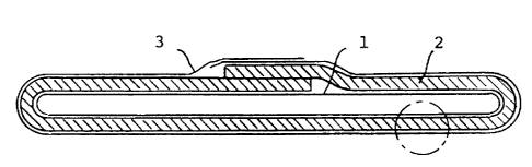
Fig. 1 is a cross sectional view of the lining material
of this invention in flattened state.
Fig. 2 is a partially enlarged view of the cross section
of an example of the lining material of this invention as
shown generally in the circular portion in Fig. 1 by a dotted
line.
Fig. 2A is a partially enlarged view of the cross section
- 16 -
2040186
of another example of the lining material of this invention as
shown generally in the circular portion in Fig. 1 by a dotted
line.
Fig. 3 is a cross section of an example of the inner
tubular film having three layers.
Fig. 4 is a partially enlarged view of the cross section
of still another example of the lining material of this
invention as shown generally in the circular portion in Fig. 1
by a ddoted line.
Fig. 4A is a partially enlarged view of the cross section
of further example of the lining material of this invention as
shown generally in the circular portion in Fig. 1 by a dotted
line.
Fig. 5 is a plan view showing a terminal end of the
lining material bound to a drawing belt for inserting the
lining material into a pipe line.
Fig. 6 is a cross sectional view showing the state of the
lining material inserted into a pipe line.
Fig. 7 is a partial cross sectional view showing the
state of the lining material merely internally inflated.
Fig. 8 is a partial cross sectional view showing the
state of the lining material brought into tight contact with
the inner surface of a pipe line.
In Fig. 1 showing an example of the lining material in
flattened state, a flexible tubular film 1 is overlaid with an
- 17 -
2040186
FCM-sheet 2. This film 1 is air-tight and elastic and is
capable of being expansively inflated by inner pressure. The
sheet 2 is somewhat longer in width than the film 1.
Accordingly, the sheet 2 is lateral along the outer
circumference of the film 1 and the both side end portions are
slidably overlapped. The sheet 2 is overlaid with a plastic
film 3 which is easily capable of being split off from the
sheet 2. This film 3 is fluid-impervious so that it can
inhibit evaporation of a solvent contained in the sheet 2.
The film 3 is overlapped, as in the sheet 2, in its side end
portions to prevent the sheet 2 from exposure to the air.
In Fig. 2 showing an enlarged cross section of an example
of the lining material wherein the FCM-sheet 2 interposed
between the films 1 and 3, a fabric 4 and a mat 5 of highly
strong fiber are impregnated with a liquid thermohardenable
resin 6. No limitation exists in the sort of the fabric 4.
Any kind of the inorganic or organic fabrics can be used but a
fabric made of glass fibers or polyester can preferably be
used as the fabric 4. Illustrative of the highly strong
fibers constituting the mat 5 are, for example, glass fibers,
carbon fibers, aramide fibers, polyester fibers and polyamide
fibers. Usually, chopped strand of glass fibers are
preferably used for the mat 5. No particular limitation
exists in the position of the fabric 4 in the sheet 2, but the
fabric is preferably in a position near the outer surface of
- 18 -
2040186
the sheet 2 due to the reason that the fabric 4 in such
position prevents abrasion of the resin between the sheet 2
and the inner surface of a pipe line.
In this case, the fabric 4 in such position has
preferably a water-repellent finish and this water-repellency
is imparted to the fabric by covering the fibers constituting
the fabric with a hydrophobic substance or introducing
hydrophobic groups into the molecules constituting the above
fibers thereby decreasing the wetness with water on the
surface of the fibers. The treatment for imparting water-
repellency to the fibers is carried out by the use of one or
more of water-repellents of fluorine or silicone series. The
water-repellents of fluorine series are organic high molecular
compounds having high molecules of polyacrylic esters or the
like as main chain and fluorocarbon chains in side chains. In
order to apply these water-repellents to the fibers, these
water-repellents are dispersed in water to form an emulsion
and the fibers are then dipped into the emulsion. These
water-repellents display their water-repellency due to the
fact that their fluorocarbon chains have poor critical surface
tension. Specifically, copolymers containing esters of
perfluoroalkanoic acids as predominant component are
preferable as the water-repellents of fluorine series. On the
other hand, the water-repellents of silicone series have a
main chain wherein silicon atoms and oxygen atoms are arranged
- 19 -
2040186
alternately and can directly bound to the molecules of fibers
constituting the fabric to form an extremely thin strong
water-repellent film on the surface of the fibers.
Specifically, methyl hydrogen siloxane is preferable as the
water-repellent of silicone series. A melamine resin or imine
resin can jointly be used for improving durability.
As the thermohardenable resin are used generally an
unsaturated polyester resin or expoxy acrylate resin usually
used for SMC. These resins have preferably a maximum
exothermic temperature of 200°C, preferably 220°C or higher
according to the high temperature curing characteristics of
JIS K-6901. As the unsaturated polyester resin is used any of
the unsaturated polyester of ortho, iso and bis type having
the above characteristics. An urethane-modified or acrylic-
modified resin can also be used as the polyester resin. As
the epoxy acrylate resin is used any of the epoxy acrylate
resin of bis-phenol or novolac type having the above
characteristics.
The above FCM-sheet 2 can optionally contain various
auxiliary substances such as a low shrinkage additive, a
filler, thickening agent and/or a curing catalyst.
Illustrative of the low shrikage additive are, for example, a
thermoplastic rubber such as styrene-butadiene-styrene block
copolymer, and a thermoplastic polymer such as polystyrene,
polyethylene, methyl polymethacrylate, polyvinyl acetate, a
- 20 -
2040186
saturated polyester, an urethane-modified saturated polyester
and/or polycaprolactone. The proportion of the low shrinkage
additive to the thermohardenable resin is desirably as
follows: the thermohardenable resin/the low shrinkage
additive = 50-90/50-10. Illustrative of the filler are, for
example, inorganic substances having chemicals-resistance,
especially acid-resistance such as barium sulfate, talc,
alumina, aluminum hydroxide and/or glass powder. The filler
is used in an amount of 15-200 parts by weight based on 100
parts by weight the total amount of the thermohardenable resin
and the low shrinkage additive. Illustrative of the
thickening agent are, for example, magnesium oxide and/or
magnesium hydroxide. The thickening agent is desirably used
in an amount of 0.5-5.0 parts by weight based on 100 parts by
weight of the total amount of the thermohardenable resin and
the low shrinkage additive. As the curing catalyst is used an
organic peroxide having a decomposition temperature of 60-
90°C, preferably about 70°C for obtaining a half-life of 10
hours. Illustrative of the curing catalyst are, for example,
cumyl peroxyneodecanoate, tert-butyl peroxyoctoate, tert-butyl
peroxyisobutyrate, 1,1-bis(tert-butyl peroxy)3,3,5-
trimethylcyclohexane, benzoyl peroxide and succinic peracid.
An organic peroxide having a decomposition temperature higher
than 90°C for obtaining the half-life of 10 hours is slow in
reaction velocity so that the curing time becomes longer. On
- 21 -
2040186
the other hand, an organic peroxide having a decomposition
temperature lower than 60°C causes premature gellation of the
resin so that the operation for impregnating the fabric 4 and
the mat 5 with the resin 6 becomes extremely difficult. The
curing catalyst is desirably used in an amount of 0.5-4.0
parts by weight based on 100 parts by weight of the total
amount of the thermohardenable resin and the low shrinkage
additive.
In addition to the above auxiliary substances, a colorant
such as dye or pigment and other additive such as a
stabilizer, etc. may be incorporated into the resin 6.
Finally, the mat is used desirably in an amount of 15-150
parts by weight based on 100 parts by weight of the total
amount of the thermohardenable resin and the low shrinkage
additive.
Specifically, the inner tubular film 1 is desirably made
of a polyester which is a synthetic resin having heat-
resistant and strong and is moderatly expansive or stretchable
by inner pressure. The tubular film 1 has preferably at least
two-layer structure wherein the inner surface is a layer of
polyolefin, preferably polypropylene having poor water vapor
permeability and the outer surface is a layer of polyester.
Most preferable as the tubular film 1 is a three-layered film
as will be described in detail herein after. Specifically,
the outer plastic film 3 is desirably made of a polyester as
- 22 -
~a4a~s6
in the case of the tubular film 1.
The FCM-sheet 2 can be manufactured firstly by mixing the
thermohardenable resin 6 with one or more of the optional
ingredients such as low shrinkage additives, fillers,
thickening agents curing catalysts and/or colorants to form a
composite substance and then impregnating a combination of the
fabric 4 and the mat 5 of a highly strong fibers. More
precisely, the plastic film 3 is overlaid with the fabric 4
such as a glass cloth and the liquid thermohardenable resin 6
in a given amount is applied onto the surface of the fabric 4.
The highly strong fibers such as glass fibers are then
dispersed on the surface of the resin 6 while cutting the
fibers by a cutter, thereby forming a mat 5 on the surface of
the resin 6. On the other hand, the thermohardenable resin 6
is applied onto a separate plastic film and the resin-coated
film is placed on the mat 5 in such manner that the surface of
the film on which the resin 6 has been coated by contacted
with the mat 5 and a mixture of the fabric 4, the mat 5 and
the resin 6 interposed between the film 3 and another plastic
film is pressed externally to impregnate a combination of the
fabric 4 and the mat 5 sufficiently with the resin 6. The
sheet thus obtained is then heated at a predetermined
temperature, e.g. at 40°C to partially cure the resin 6
thereby it is somewhat thickened. The viscosity of the resin
6 after thickening is preferably 10000-100000 poise as
- 23 -
2040186
composite substance. If the viscosity is too low, it will
become difficult to peel off the plastic film, thus making
workability inferior. On the other hand, if the viscosity is
excessively higher, the resultant lining material will be
deteriorate in adhesion to the inner surface of a pipe line,
thus making it impossible to provide the pipe line adequately
with the lining. The thickened FCM-sheet 2 thus obtained is
cooled and stored at a temperature lower than 20°C whereby the
thickening effect is reduced and the FCM-sheet 2 can be stored
for a long period of time.
The lining material of this invention wherein the FCM-
sheet 2 is interposed, for example, between the films 1 and 3
can be manufactured from the FCM-sheet 2 in the following
manner: The FCM-sheet 2 is placed on a board in such manner
that the film 3 faces the board, and the plastic film on the
opposite side is peeled off. The tubular film 1 is then
placed on the exposed sheet 2 at the central part thereof, and
both end portions of the sheet 2 is laminated on the tubular
film 1 in such manner that both side edge portions are
slidably overlapped with each other to cover the film 1
entirely with the sheet 2. The sheet 2 as a whole in the form
of a tube, though its edge portions are overlapped each other,
is then overlaid with the plastic film 3 both edges of which
are overlapped each other as in the case of the sheet 2,
thereby forming the lining material having the cross section
- 24 -
2040f86
as shown in Fig. 1.
In Fig. 2A showing an enlarged cross section of another
example of the lining material wherein the FCM-sheet 2 has a
non-woven fabric layer 9' on the opposite side of the fabric
4, the non-woven fabric layer 4' looks similar to the mat 5 of
the FCM-sheet but is more dense in structure and is composed
of a thick layer of well entangled strong organic fibers such
as polyester or polyamide fibers. The non-woven fabric layer
4' is apparently differentiated in this respect from the mat 5
which is preferably made of inorganic fibers such as glass
fibers or carbonaceous fibers. The FCM-sheet shown by Fig. 2
affords a hard lining on the inner wall of a pipe line. It
has been found however that when a pipe line with the lining
derived from the FCM-sheet shown by Fig. 2 is used as a sewage
pipe line, the lining tends to be worn out by sand or other
hard solid particles contained in sewage. While the pipe line
is used continuously, the degree of abrasion is gradually
increased to deteriorate strength of the lining, thus
resulting in rupture of the pipe line by external water
pressure. In order to enhance abrasion-resistance of the
sheet 2, therefore, the mat 5 is overlaid with a non-woven
fabric layer 4' made preferably of an organic fibers such as
polyester and/or polyamide so that the non-woven fabric layer
4' may form the innermost layer of the sheet 2 being in
contact with sewage. Accordingly, the non-woven fabric layer
- 25 -
204016
is positioned on the opposite side of the fabric layer.
Inorganic fibers such as glass fibers or carbonaceous fibers
are not suited as a material for constituting the non-woven
fabric because of their inferior strength against abrasion.
The non-woven fabric layer 4' and the fabric layer 4 as well
as the mat 5 are integrally impregnated with the
thermohardenable resin 6. The lining material shown in Fig.
2A is manufactured, for example, in a similar manner to that
described with respect to the lining material shown in Fig. 2.
First of all, the fabric layer 4 is spread on the film 3 and
a predetermined amount of the thermohardenable resin is
applied thereonto. A chopped strand of fibers of high
tenacity such as glass fibers is then placed on the resin to a
certain thickness to form the mat 5. On the other hand, the
film 1 is overlaid with the non-woven fabric layer 4' and then
the thermohardenable resin 6 is applied thereonto. Both
laminates thus prepared are then overlapped so that the resin
coated surfaces are contact with each other, and finally the
overlapped laminates are pressed externally. It is
unnecessary for the non-woven fabric layer 4' to cover the
whole surface of the sheet 2. The non-woven fabric layer may
have a width sufficient to cover only the surface of the sheet
2 in contact with sewage. It is a matter of course, however,
that the non-woven fabric layer 4' may cover all the surface
of the sheet 2. The properties and functions of the films 1
- 26 -
204016
and 2 in the lining material shown in Fig. 2A are identical
with those of the lining material shown in Figs. 1 and 2.
In Fig. 3 showing the cross section of an inner tubular
film 1 having three layers, the film comprises an outer layer
7, an intermediate layer 8 and an inner layer 9. The outer
layer 7 comprises a biaxially oriented film of a plastic which
is easily peeled off from the FCM-sheet 2 and is excellent in
tensile strength and heat-resistance. Specifically,
polyethylene terephthalate or nylon 66 is suited for the
plastic constituting the outer layer. Such plastic has a
melting point above 250°C and so is not deteriorated even by
the heat evolved during the curing reaction of the
thermohardenable resin. Thus, the inner tubular film 1 can be
peeled off from the inner surface of the FCM-sheet 2 after it
is cured. As the tensile strength of the outer layer 7 is
excellent, it withstands the tensile force for peeling off the
tubular film 1 from the sheet 2 after its curing.
The intermediate layer 8 comprises a biaxially oriented
film of a plastic which possesses flexibility, toughness and
high tensile stress at a low degree of elongation. Nylon 6 is
suitable as the plastic. Polyethylene terephthalate or nylon
66 is excellent in strength but is inferior in flexibility and
toughness. When the lining material is folded in flattened
state, the inner tubular film 1 is especially strongly folded
so that the so-called "blushing" takes place in the folded
- 27 -
2040186
edge portions and pinholes may be formed in the extreme cases.
Accordingly, the intermediate layer 8 is provided inside the
outer layer 7 to maintain flexibility of the inner tubular
film 1 and at the same time to prevent the formation of
pinholes thereby preventing intrusion of water vapor.
The inner layer 9 comprises a non-oriented film of a
plastic which possesses poor water-permeability and resistance
to heat to such a degree that the plastic is not molten or
deteriorates by steam. Polypropylene is suitable as the
plastic but should not be oriented. Polypropylene has poor
water vapor transmission and a melting point of 130-140°C so
that it withstands steam. However, polypropylene cannot
withstand the heat (about 200°C) during the curing of the
sheet 2 but the inner layer is positioned furthermost to the
sheet 2 and is contacted with steam of a lower temperature.
Accordingly, polypropylene is not heated above its melting
point and covers the inner surface of the tubular film 1 to
prevent transmission of water vapor. In case the inner layer 9
is used under such condition that it may be exposed to high
temperatures, it is preferable to use a block copolymeric
polypropylene having a high melting point. In general, non-
oriented polypropylene has high tensile elasticity and
contraction by heat but is poor in tear resistance.
Accordingly, the use of non-oriented polypropylene causes
contraction by heat of heated steam and partial crack in the
- 28 -
2040186
extreme case so that the intermediate layer and the outer
layer can be contacted directly with heated steam. As the
film of this invention is not oriented, however, there is no
fear of contraction even by heating. Further, the film is
extremely low in tensile elasticity but is high in tear
resistance. Accordingly, the film is not cracked by heating
and ensures inhibiting the transmission of steam.
The inner tubular film 1 of this invention is
manufactured by integrally binding each plastic film of the
outer layer 7, the intermediate layer 8 and the inner layer 9
by the aid of a binder of isocyanate series as dry laminate,
making the integrally combined film tubular, and heat-sealing
the inner layer 9 at both side ends. Alternatively, the inner
film 1 may be manufactured by bringing both side ends of the
integrally combined film into contact with each other and
heat-sealing the film with a fraction of a tape having the
same structure as of the inner tubular film 1 in such manner
that the layer corresponding to the inner layer 9 of the tape
may be faced to the inner layer 9 of the film 1.
In Fig. 4 showing a partial enlarged view of still another
example of the lining material, the FCM-sheet 2 is interposed,
as in the example of Fig. 1, between the inner tubular film 1
made of a heat-resistant synthetic resin and the outer film 3.
In this example, however, a liquefiable film 9A, i.e.
polystyrene film 9A as a third film is further interposed
- 29 -
X040186
between the FCM-sheet 2 and the tubular film 1. This
polystyrene film 9A can be provided around the film 1 by
covering the tubular film 1 with a polystyrene tube or winding a
polystyrene film spirally on the tubular film 1. These films 1
and 9A are then overlaid with the FCM-sheet 2 and the outer film
3 in the same manner as shown in Fig. 1.
The thermohardenable resin 6 contains monomeric styrene
as a reactive solvent. The polystyrene film 9A as a
liguefiable film is dissolved in this monomeric styrene and as
a whole forms a viscous concentrated solution of polystyrene
in monomeric styrene. This solution is kept between the inner
tubular film 1 and the FCM-sheet 2. In this case, the fabric
4 and the mat 5 of highly strong fibers may be the same as
described with respect to Fig. 1. The monomeric styrene
participates in the reaction as a cross linking agent on the
curing of the unsaturated polyester resin 6 and is entirely
consumed at the stage the curing of the unsaturated polyester
resin 6 has been finished.
As another example of the liquefiable film 9A is used a
film of ethylene-vinyl acetate copolymer (EVA). In this case,
EVA film 9A is molten by the heat evolved by the curing of an
unsaturated polyester resin 6 in the FCM-sheet 2, and the
molten EVA film 9A is again solidified, after completion of
the curing reaction of the unsaturated polyester resin 6, by
cooling to form an integrally combined fabric-fiber-reinforced
- 30 -
2040186
plastic lining.
The process of this invention for providing pipe lines
with a fabric-fiber-reinforced plastic lining will now be
explained in detail with reference to the drawings.
At the outset, the outer film 3 for the purpose of
sealing the FCM-sheet 2 to inhibit evaporation of liquids,
e.g. the thickened liquid unsaturated resin 6 and styrene, is
removed by peeling it off from the lining material prior to
using it for pipe lining. The lining material is then
inserted into a pipe line preferably in such manner that at
one terminal end of the pipe line a lining material is
connected at its one end to the drawing belt previously passed
through the pipe line from the other terminal end.
In Fig. 4A showing a partially enlarged view of further
example of the lining material, both of the non-woven fabric
layer 4' and the liquefiable film 9A are incorporated into the
sheet 2. In this case, the non-woven fabric layer 4' forms,
as shown in Fig. 2A, the innermost layer of the sheet 2 on the
opposite side of the fabric layer 4 for the same reason as
described with respect to Fig. 2A (for achieving high
abrasion-resistance against sewage containing sand and the
like hard solid particles). Accordingly, the liquefiable film
9A is positioned between the fabric layer 4 and the mat 5,
both of which are impregnated with the thermohardenable resin
6. In the structure of the lining material shown in Fig. 4A,
- 31 -
2040186
however, an EVA film is not used as the liquefiable film 9A
since it inhibits evaporation of styrene contained in the
sheet 2 on curing of the thermohardenable resin. The lining
material shown by Fig. 4A can be manufactured, for example, by
overlaying a laminate of the film 3 and a fabric layer 4
impregnated with the thermohardenable resin 6 with the mat 5
made of fibers of high tenacity such as glass fibers and
thereafter overlapping the laminate thus prepared with a
laminate of the film 1 and the non-woven fabric layer 4'
impregnated with the thermohardenable resin 6 so that the mat
may be faced to the non-woven fabric layer 4'.
Fig. 5 is a plan view showing the lining material and the
drawing belt in this state. The drawing belt 10 forms an
expanded portion 11 at its front end. The lining material 12
in flattened state is overlaid at its one end with the end
portion of the drawing belt 10 and folded to wrap the expanded
portion 11 therewith as shown in Fig. 5. The lining material
12 is fastened externally with a rope 13 together with the
drawing belt 10. The lining material 12 can thus be connected
in such manner to the drawing belt 10 and the expanded portion
ensures this connection. Accordingly, the drawing force of
the belt 10 can be exerted evenly to the lining material 12.
When the lining material 12 in flattened state is drawn
into the pipe line by the action of the drawing belt 10, the
lining material 12 is preferably pushed down in its central
- 32 -
2040180
part at the entrance of the pipe line so as to form "U" shape
in cross section.
Fig. 6 is a cross sectional view of the pipe line through
which the lining material is introduced in "U" shape in cross
section while being kept in flattened state. In Fig. 6, the
lining material consists of the FCM-sheet 2 and the inner
tubular film 1 in this example (the outer film 3 has been
peeled off) is inserted in flattened state but in the bent
state in "U" shape into the pipe line 14. The lining material
has an outer peripheral length slightly shorter than the inner
peripheral length of the pipe line 14. Accordingly, the
lining material in flattened state has a width significantly
larger than the inner diameter of the pipe line 14. If the
lining material is inserted in flattened state into the pipe
line and pulled forward by the action of the drawing belt,
both side edges of the flattened lining material will strongly
be pressed against the inner surface of the pipe line 14 so
that both side edge portions can be damaged by friction and
abrasion. Accordingly, the lining material is bent in the
lateral direction so as to form "U" shape in cross section,
whereby the friction between the moving lining material and
the inner urface of the pipe line becomes minimum and the
lining material is pulled forward smoothly while making the
shape of the lining material in cross section in compliance
with the curvature of the inner surface of the pipe line 14.
- 33 -
204016
When the lining material has fully been inserted into the
pipe line, both ends of the lining material are allowed to
extend from both ends of the pipe line. Both ends of the
lining material are then provided with a proper sealing tool
so that one end of the lining material is closed and a
pressurized fluid is introduced into the lining material
through the sealing tool on the other side to inflate the
lining material.
Fig. 7 is a partial cross sectional view showing the
state of the lining material in the pipe line internally
inflated at the initial stage, i.e. the state of the lining
material ordinarily inflated by a pressurized fluid as
described above. As the pressurizing fluid for inflating the
lining material, compressed air or pressurized water is used,
but the use of compressed air is preferable. In Fig. 7, a
clearance 15 is formed between the pipe line 14 and the FCM-
sheet 2. This is due to the reason that the outer peripheral
length of the inner tubular film 1 is originally so selected
that it is somewhat shorter than the inner peripheral length
of the pipe line 14.
By elevating the inner pressure in the lining material,
the inner tubular film 1 is expanded and the FCM-sheet 2 is
slidably moved at the overlapped portion in such manner that
both ends of the sheet 2 are moved in opposite directions as
shown by the arrow marks in Fig. 7 to increase the peripheral
- 34 -
2040186
length of the sheet 2.
In case compressed air is used for inflating the lining
material, its pressure is normally within the range from 0.3
to 1.0 kg/cm2G. In case the lining material is merely
inflated, a pressure of about 0.3 - 0.5 kg/cm2G is necessary.
On the other hand, a somewhat stronger pressure, e.g. 0.5 - 1
kg/cm2G is necessary for expanding the lining material to
bring it into tightly contact with the inner surface of the
pipe line.
Fig. 8 is a partial cross sectional view showing the
state of the lining material at the final stage in the pipe
line where the lining material is tightly contacted with the
inner surface of the pipe line. The above 2-stage
pressurizing treatment for realizing the state as shown in
Figs. 7 and 8 can be carried out continuously. After the
pressurizing treatment, it is then confirmed whether or not
the lining material is tightly contacted over its full length
with the inner surface of the pipe line. Next, the
pressurized fluid is evacuated and then a fluid for heating
the lining material internally is introduced into the pipe
line. Usually, steam is used as the fluid for heating the
lining material. The steam pressure in this case is usually
within the range of 0.3 - 1.0 kg/cm2G and the heating is
continued until the thermohardenable resin 6 in the FCM-sheet
2 is completely cured. In case the FCM-sheet 2 contains
- 35 -
2040186
styrene or EVA, this substance is also cured integrally with
the thermohardenable resin. The time necessary for curing the
resin is generally within the range from 30 minutes to 2
hours, preferably one hour.
After completion of the curing, steam is replaced with
compressed air to cool the lining material. By heating, the
thermohardenable resin in the FCM-sheet is cured integrally
with the fabric and the mat of highly strong fibers to form a
fabric-fiber-reinforced plastic lining which is strongly
bonded as a rigid pipe to the inner surface of the pipe line.
Finally, the inner tubular film 1 is removed by peeling it off
from the resultant fabric-fiber-reinforced plastic lining as a
rigid pipe. In this case, the peeling of the tubular film 1
is preferably carried out by pulling a leader belt previously
passed through the inside of the pipe line and connected to
one end of the tubular film 1 while everting it.
According to the present invention, a number of
advantages can be achieved by using the specific FCM-sheet and
the specific pipe-lining process.
The FCM-sheet used in the present invention comprises the
fabric and the mat of highly strong fibers impregnated with
the thermohardenable resin is different in strength from SMC
comprising only a mat of similar strong fibers impregnated
with a thermohardenable resin. In case of SMC, the lining
material is locally stretched or broken in the extreme case.
- 36 -
_. ~o4olss
In case of the FCM-sheet, the lining material is so strong
that it has a high tensile strength and is quite free of local
elongation or break even at the time of being drawn into a
pipe line. In addition, the FCM-sheet withstands local
elongation and forms no wrinkle on sliding of the overlapped
portions for increasing the peripheral length of the FCM-
sheet, i.e. the diameter of the FCM-sheet. Thus, an adequate
lining of the FCM-sheet under proper tension can be made
overall the inner surface of the pipe line. As the overlapped
portions of the FCM-sheet is tacky but slidably movable in
opposite directions to increase its peripheral length under a
relatively low inner pressure without causing any mutual
fusion, the lining operation can easily be carried out over
full length of the pipe line without causing any trouble.
In case of the FCM-sheet having the water-repellent
fabric, it prevents external intrusion of moisture or water
into the liquid thermohardenable resin so that the curing
reaction of the FCM-sheet is not disturbed. As the water
repellent fabric inhibits intrusion of external water even
after the curing reaction, intrusion of water into the pipe
line can be prevented even if the structure of the FCM-sheet
is not sufficiently dense. It is a matter of course that the
lining treatment can be made even if the pipe line is wetted.
In case of the lining material having three layers as the
inner tubular film, the following technical merits can be
- 37 -
2040186
achieved. As a film of high strength is used for the outer
layer and an intermediate layer exists inside of the outer
layer, the inner tubular film has high mechanical strength and
moderate flexibility and so is convenient in handling. Even
if the so-called "blushing" phenomenon of the outer layer
takes place in case of folding the lining material in
flattened state, the existence of the intermediate layer
possessing flexibility, toughness and high tensile stress at a
low degree of elongation prevents the formation of pinholes
which permit intrusion of water vapor into the FCM-sheet and
induce bad influence on the lining material. In case of a
pipe line to be treated has a branched portion, a troublesome
problem occurs in the lining treatment. When steam is
introduced into the lining material applied to the inner
surface of the pipe line, the inner tubular film is expanded
under the steam pressure to allow the FCM-sheet to expand into
the recession of the branched portion. In this invention,
however, a film of high strength is used as the outer layer
and biaxially oriented films are used for both outer and
intermediate layers so that the inner layer is not excessively
expanded and the FCM-sheet is prevented from local reduction
in thickness. When the lining material is heated with steam,
the inner layer prevents permeation of steam while the outer
layer withstands the heat (about 200°C) of the exothermic
reaction during the curing of the thermohardenable resin. The
- 38 -
2040186
inner layer is not so high in heat-resistance but is not
excessively heated as it is contacted with steam. After
completion of the curing reaction, the inner tubular film is
removed by peeling it off from the resultant fabric-fiber-
reinforced plastic lining while everting the film by drawing
it with a drawing belt. The heavy load in this case is -
undertaken by the film of the outer layer which has been
biaxially oriented and has strong tensile strength. Further,
the outer layer has high heat-resistance and is not molten at
the time of curing the thermohardenable resin so that the
inner tubular film having the outer layer in contact with the
resultant fabric-fiber-reinforced plastic lining can easily be
peeled off therefrom. Accordingly, the lining of a pipe line
with the fabric-fiber-reinforced plastic lining can be
attained without any trouble by the use of the inner tubular
film having such three layers.
In case of the lining material as shown in Fig. 4 or 4A,
the liquefiable film is dissolved in a polymerizable solvent
but is solidified to form an integral plastic lining with the
FCM-sheet. In case the inner pressure at the time of curing
the FCM-sheet is insufficient, a dense fabric-fiber-reinforced
plastic lining cannot be obtained and a number of interstices
are formed in the fabric and/or mat structure. Even if that
is the case, the liquefied resin occupies the interstices and
solidified integrally with the cured resin in the sheet.
- 39 -
Thus, the bonding strength of the fabric-fiber-reinforced
plastic lining to the inner surface of the pipe line is
significantly enhanced.
In case of the lining material having the non-woven
fabric layer as the innermost layer thereof, the abrasion-
resistance of the lining material against running sewage
containing sand and the like abrasive solid particles. This
technical effect can be demonstrated by the following
experimental result: A non-woven fabric layer made of 100 d
polyester monofilament and having a fabric weight of 65 g/m2
and a thickness of 0.6 mm was used as the non-woven fabric
layer, and a lining material as shown in Fig. 2A was
manufactured by using the non-woven fabric layer and used in
the experiment. Next, this lining material was applied onto
the inner surface of a Hume concrete pipe of 20 mm in
diameter. For comparison, a similar lining material devoid of
the non-woven fabric layer was also applied onto the inner
surface of the same Hume concrete pipe as control. Water
containing 5o by weight of silica sand No. 2 as a model of
sewage was continuously passed through the lined Hume concrete
pipe at a flow rate of 10 meters per minute. The depth of
abrasion on the lining material was measured after the lapse
of one month and the depth per year was calculated from the
measured value. As a result of the measurement and
calculation, it has been found that the depth of abrasion in
- 40 -
. 2040186
terms of mm/year is 0.7 in case of the lining material covered
with the non-woven fabric layer, while the depth is 3.4 in
case of the lining material devoid of the non-woven fabric
layer. Thus, abrasion of the lining material lacking of the
non-woven fabric layer is about 5 times as much as the lining
material provided with the non-woven fabric layer as the
innermost layer. In general, sewage involves waste effluent
and rainwater among which the waste effluent contains solid
matters smaller in the value of specific gravity and hardness.
Accordingly, abrasion of the lining material caused by the
waste effluent is considered to be rather slight. Although
abrasion of the lining material caused by rainwater containing
soil and sand is certainly great, sewage of a high flow rate
as demonstrated by the model of experiment is rather rare in
actual cases, and so abrasion of the lining material is
considered to be less the value above calculated in the
majority of cases. Thus, the lining material provided on the
innermost surface thereof with the non-woven fabric layer
serves to maintain for a long period of time the initial
strength against abrasion.
In the liquid thermohardenable resin contained in the
FCM-sheet, a thermoplastic polymer as a low shrinkage additive
is dispersed in the form of fine particles. When a rapid
exothermic reaction takes place on the curing of the
thermohardenable resin, the thermoplastic polymer particles
- 41 -
a 2040186
undergo rapid thermal expansion by the heat to compensate
shrinkage of the thermohardenable resin accompanied by the
curing reaction. When the curing of the thermohardenable
resin is finished, the exothermic phenomenon is ceased and the
temperature is depressed whereby the thermoplastic polymer
particles are contracted. At that time, however, the
thermohardenable resin has been cured and forms three
dimensional linkages so that it can no longer be shrinked.
Accordingly, the thermoplastic polymer alone is contracted
while forming voids inside, and thus a lining free of
contraction as a whole can be formed. Accordingly, the lining
material of this invention is not contracted on curing and is
firmly bonded to the inner surface of the pipe line without
being peeled off.
As the filler, the use of an acid-resistant substance
such as barium sulfate, talc, glass powder and the like is
effective for making the lining material anti-corrosive.
Aluminum hydroxide, magnesium hydroxide and the like are
themselves weak in acid-resistance but can preferably be used
in the present invention.
As has been described hitherto, the technical effects
achieved by the FCM-sheet of this invention are excellent and
the lining material of this invention is particularly suitable
for the reinforcement of sewage pipes.
It is understood that the preceding representative
- 42 -
2040186
embodiments may be varied within the scope of the present
specification both as to ingredients and treatment conditions,
by one skilled in the art to achieve essentially the same
results.
As many widely, different embodiments of this invention
may be made without departing from the spirit and scope
thereof, it is to be construed that this invention is not
limited to the specific embodiment thereof except as defined
in the appended claims.
- 43 -