Note: Descriptions are shown in the official language in which they were submitted.
B-27~95 2 0 ~ 3 ~
~ODU~AR BhASTING ~Y~TE~
TEC~NICAL FIE~D
The present invention relates to explosives ancl to
components and systems useful in the detonation of
explosives. In particular, the invention relates to
modular components from which a system or transmitting
a detonation signal can be constructed to achieve a
predetermined detonation pattern.
,~
BAC~G~OUND OF TXE INVENTION
In blasting operations, various devices are used to
transmit a blast sigllal from a remote initiation
location to explosives in a borehole. These devices
include detonating cord, safety fuses, energy
transmission tubes, blasting caps and various connectors
arranged in such a manner as to detonate explosives in a
desired sequence and pattern. In nonelectric systems,
delay elements may be interposed along signal
transmission lines on the surface or in the boreholes to
achieve sequential initiation of explosive charges.
In a typical arrangement, trunklines carry the
blast signal from an initiator to downlines or to
surface delay devices. Both trunklines and downlines
are lengths of detonating cord or other signal
transmitting devices. The trunkline is the portion of
the transmission line on the surface, connecting
boreholes. A downline is connected to a trunkline and
extends into a borehole. The downline transmits the
signal from the trunkline or surface delay element to
the explosive in the borehole. The downline may also be
attached to delay devices in the boreholes and/or to
instantaneous blasting caps in the borehole.
The use of delay devices to detonate explosives in
a predesigned pattern at predetermined times can be
useful to achieve the desired breakage of rock. This is
particularly true when the explosives within a borehole
are "decked", that is, loaded in explosive sections that
are detonated at different times. Delay devices also
help to reduce the noise and vibration common to
blastiny operations which is important in light of
governmental regulations and complaints from nearby
2~2~
residents. Due to these advantages, the industry has
made wider use of delay devices.
To provide different delay periods downhole and to
accommodate holes of varying lengths it has been common
practice to place a desired delay elem~ant on one end of
a single transmission device. Typically a series of
signal transmission tubing lengths are provided for each
delay. For example, a 25 millisecond delay cap may be
attached to various lengths of single transmi sion
tubing, e.g., 10 feet, 15 feet, 20 feet and 25 feet.
Unfortunately, this requires a large inventory of both
diEferent delay elements and different lengths of
transmission tubing.
There is a continuing ne~d to provide a reliable,
simple, yet versatile system which will allow connection
of explosive charges in a pattern. The present modular
system has the advantage of providing a system which is
easy to use while permitting easy variation of blasting
patterns~ The present invention also permits a
substantial reduction in inventory by accommodating a
great variety of combinations from a few elements. The
present system also has the advantage that the signal
tubing can function as both the downline and the
trunkline. Further, the system can be utilized to
provide multiple pathways for detonation singles between
boreholes thus increasing reliability of detonation.
,
.
B~MMA~Y OF T~E INV~NTION
The present invention utilizes the bi-directional
capability of signal transmission tubes along with the
following modular units: a surface relay unit, a donor
unit, and a detonator unit. Each modular unit will
delay the propagation of an initiation signal a distinct
and known amount of time. The modular system permits
greater versatility in operation because time delays may
be easily varied by exchanging ~urface relay units for
detonator units. For example, two surface relay units
may be attached to each end of the donor unit. In
another embodiment, a surface relay unit and a detonator
unit may be attached to each end of a donor unit. In
yet another embodiment, two detonator units may be
attached to each end of a donor unit. Thus, a system
can be constructed in which the combination of a donor
unit with relay units and detonator units may be
assembled to achieve a number of different purposes and
a wide variety of delay periods.
The donor unit is comprised of a length of signal
transmission line to which donor mini-caps are affixed
at each end. The transmission line is preferably a tube
containing a reactive material which propagates a signal
by generation of a plasma front within the tube. These
transmission lines can be initiated at varying locations
along their length. Upon initiation of the signal
transmission line, the signal will be transmitted to
each end o~ the transmission line from the point of
initiation. The signals then initiate the donor mini-
caps located at each end of the signal transmis~ion
line. The donor ~ini-caps are capable of initiating the
relay unlt and the detonator unit, but are incapable of
initiating the midpoint of another transmission line and
.
preferably are not capable of initiating the
transmission line to which they are attached.
The donor mini-cap, or cap used in blasting,
represents another novel aspect of the present
invention. Each mini-cap .is comprised of a shell having
a thin bottom portion which will blow out upon
initiation of the explosive contained within the mini-
cap. The explosive is placed at the bottom of the cap.
Provided above the explosive charge is a reduced
diameter section leading into an empty chamber which at
the other end has a second reduced diameter section.
Above the second reduced diameter section is a section
of sufficient diameter to receive signal transmission
tubing into operative association with the mini-cap.
Preferably, the mini-cap explosive charge contains a
desensitizing agent to reduce sensitivity to shock
initiation. For example, a composition containing from
about 15% to 35% clay, the remainder being explosive
material, is suitable for use in the mini-cap.
The relay unit comprises a block containing a
detonator uni~. The block is constructed so as to allow
a donor mini-cap to be held by the block or the
detonator or both in operative association with the
detonator element of the block. The block is also
provided with a second receptacle for allowing the
detonator to be in operative association with one or
more transmission lines at any point along the lines
lengths. The detonator element in the relay unit may be
an instantaneous detonator or a delay detonator of
desired delay.
Another aspect of the present invention is a
detonator which may be assembled with a donor mini-cap.
The detonator is comprised of a wall defining a shell
2~23~
having a first and second end. The first end is open
and the second end i~ closed. ~,ocated at the second end
is an explosive charge which will provide in-hole
initiation of a primer with which it iB associated. The
explosive charge is also of sufficient strength to
initiate a signal transmission line when both the line
and the detonator are in operative engagement with a
relay unit. The explosiva charge is initiated by the
detonation of the donor mini-cap attached to said
detonator. Above the explosive charge is a delay
element for providing either an instantaneous or a
predetermined delay. Adjacent the delay element is an
ignition transmission element. Adjacent the ignition
transmission element is a reduced diameter section
containing a primer, the reduced diameter section being
dimensioned such that it will ignite the primer upon
detonation of the reduced diameter section. Adjacent a
second reduced diameter section, the wall is dimensioned
to receive a donor mini-cap and is provided with
connecting means to connect the donor mini-cap with the
detonator. The connector means may be a sorew thread or
a series of deflectable ridges to provide a frictional
fit.
By combining the units, a modular blasting system
2S is created comprising a donor unit having a relay
element of desired time delay connected to one end of
the donor unit and a detonator unit attached to the
other end of the donor unit. In another embodiment, a
blasting system is provided in which a donor unit has a
detonator unit attached to each end. In yet another
embodiment, the donor unit has a relay unit connected to
each end.
BRIEF DE8CRIP~ION OF ~E DRAWING8
A more complete understanding of the invention may
be had by refarence to the ~ollowing dletailed
description when taken in conjunction with the
accompanying drawings wherein like ref~erenced chara~ters
danote like parts in all views and whe:rein:
FIGURE 1 is a perspective view of a donor unit;
FIGURE 2 is a perspective view of a relay unit;
FIGURE 3a is a sectional view of 'a detonator
element to be placed in a relay element;
FIGURE 3b is a sectional view o~ another embodiment
o~ the relay element utilizing a plug engagement means;
FIGURE 3c is a sectional view of the relay element
of FIGURE 3a with a deforming charge added;
FIGURE 4 is a perspective view o~ a ferrule;
FIGURE 5a is a sectional view of a donor mini-cap;
FIGURE 5b is a sectional view of an alternative
embodiment of the donor mini-cap;
FIGURE 5c is a sectional view of the mini-cap
attached to a signal transmission line;
FIGURE 5d is a sectional viaw of the transmission
signal line in crimped connection with a donor mini-cap;
FIGURE 6 illustrates the modular components engaged
with one another;
FIGURE 7 is a schematic view o~ a detonation system
constructed with various components; and
FIGURES 8-10 schematically illustrate modular
components used to achieve decking in a borehole.
i
2 ~
DETAILED ~ESCRIPTION OF T~B INVENTION
The present invention provides a signal
transmission system using modular components which
offers unique versatility and can also provide multiple
signal paths. Using this system, a blasting pattern can
be arranged such that a proper blasting sequence,
including delays, is maintained. The invention also
provides relay units, initiator units~ and donor units
that may be used in the system to achi,eve bi-directional
and multi-directional signal transmission within a blast
pattern.
FIGURE 1 illustrates a donor unit generally
indicated as 20. The unit oomprises a length of signal
transmission line ~2 which has attached to each end a
donor mini-cap 24 or cap used in blasting. The signal
transmission line 22 has such characteristics that when
initiated at some point along its length, such as point
A in FIGURE 1, a detonation signal will be transmitted
to each end of the unit from point A as indicated by
arrows B and C~ When the signal reaches each of the
donor mini-caps, it detonates the donor mini-caps. The
signal transmission line may be any suitable signal
transmission line which will propagate a signal reliably
in both directions when it is initiated at a point along
its length. Suitable signal transmission lines are
illustrated in U.S. Patent No. 4,290,366 to Janoski, the
disclosure of which is hereby incorporated by reference.
The hollow tube contains a reactive material such that a
detonation signal is transmitted along the tube by
oxidation and the creation of a plasma front. A similar
transmission line is also disclosed in U.S. Patent No.
3,590,739 to Persson, the disclosure o~ which is hereby
also incorporated by reference. Importantly, these
. ~
20~3~
g
signal transmission lines can transmit a signal in
either direction along the length of the line. Other
suitable transmission lines may be used.
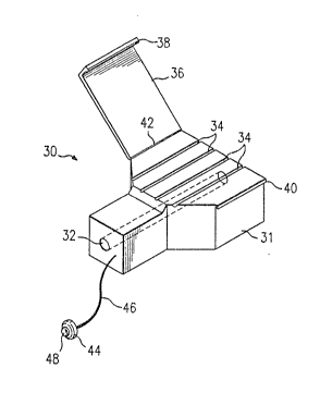
FIGURE 2 is a perspective view of the relay unit
30. The relay unit comprises a body 31 defining a
passageway 32 for receiving the detonator unit generally
shown in FIGURES 3a-3c. ~he relay element is also
provided with a means for receiving other transmission
lines in operative relationship with the detonator
element. These are comprised of g~ooves 34. A means to
hold or lock the inserted transmission lines is provided
such as a cover 36 on one side of the relay unit block
which utilizes a lip 38 extending from the cover 36
dimensioned to engage a cooperating ridge 40 on the
opposite side of the relay unit body 31. The cover 36
is preferably hingedly connected at hinge 42 which may
be flexible plastic. It is also possible to provide a
cover which snaps onto the body as a separate piece or
other appropriate mechanisms. The element also
~0 preferably includes plug 44 which is attached to the
relay unit body 31 by flexible strand 46. The plug 44
is dimensioned with a raised portion 48 which provides
frictional fit into passageway 32. The purpose of plug
44 is to prevent dirt and other debris from entering the
2~ passageway prior to assembly of the unit.
Preferably, the relay unit body is made from a
plastic material having a density of about 0.94 g/cc or
higher. Such material has been found to effectively
permit transmission of a detonation signal from a
detonator element which is placed in passageway 32 to
transmission lines in grooves 34. The distance between
the detonator and the transmission lines is close enough
that initiation of the detonator is su~ficient to
2 0 ~
initiate the transmission lines. Usually, the thickness
of the body between passageway 32 and grooves 34 is less
than about 0.030 inches. Preferably the relay units are
made of a high-impact plastic such as HDPE or 25%/75%
HDPE/LDPE and are color coded to reflect the millisecond
delay housed within each. Color coding facilitates the
correct placement of the units in the blast pattern.
FIGURE 3a illustrates the detonator element 50
which is either placed in passageway 32 of relay element
30 or used alone. The overall dimensions of the
detonator are those usPd currently in the art for caps.
It is constructed of a generally cylindrical body 60
having a closed end 62 and an open end 64. Generally,
the detonator is about 0.270 inches to about 0.300
inches in diameter and about two to four inches in
length. Adjacent to the closed end is explosive charge
66~ Adjacent to the other side of explosive charge 66
is delay element 68 which is a length of pyrotechnic
having a controlled burning rate which typically is
contained within a cylindrical body 70 which engages the
interior wall of body 60. Adjacent to the delay element
68 and cylindrical body 70 is a percussion ignition
primer element ("PIPE"~ 72. The PIPE 72 is comprised of
a ferrule 74 having an H-shaped cross section. Ferrule
74 engages the walls of th~ body 60 and provides two
smaller channels 76 and 78. In channel 76, operably
adjacent to ferrule 74, is primer 80. Primer 80 is
optional, as ferrule 75 can be designed with an
extremely thin mid-section 84 which acts as a protective
diaphragm or flyer plate.
Disposed close to open end 64 are thread surfaces
82. These surfaces interact with the donor mini-caps 24
of the donor unit 20 (shown in FIGURE 1) to hold the
donox mini-cap in operative association with the
detonator element 50. In operation, initiation of the
donor mini-cap results in a deflection of the narrow
mid-section 84 of the H-shaped ferrule 74. This
deflection th~n causes primer 80 to ignit~. Ferrule 74
can be made of aluminum or plastic and the thickness of
the mid-section 84 should be less than or equal to 0.015
inches. If no primer is used, mid-sect:ion ~4 should be
between 0.005 to 0.010 inches thick. :[gnition of primer
80 causes delay element 68 to burn which after a
predetermined delay, oauses explosive element 66 to
detonate. The detonation of explosive element 66 is of
sufficient strength to transmit the blast signals to
signal transmission lines in grooves 34 of the relay
unit body 31.
FIGURE 3b shows yet another construction of the
detonator element 50 in which the same numbers as
utilized in FIGURE 3a are used to point out similar
elements. However, in this embodiment, no thread
surfaces 82 are provided. In contrast, an engaging
means is provided by plug 86 which is cylindrical in
shape and operates by engaging the inner surfaces o~
body 60. The interior passageway through the plug 86 is
provided with resilient protrusions 88. These
protrusions 88 are dimensioned to engage in frictional
fit a protrusion on the donor mini-cap of the donor unit
and function to hold the donor mini-cap in operable
relationship with the detonator element 50. Preferably,
protrusion~ 88 are dimensioned so that they are flexible
in the direction towards closed end 62 and resist
flexing in the direction uf open end 64. This design
allows relati~eiy easy insertion of the donor mini~cap
but yet resists separation of the donor mini-cap from
the detonator element. The functioning of the detonator
of FIGURE 3b is similar to that as described for the
detonator of FIGURE 3a.
Again, in FIGURE 3c similar numerals are utilized
for reference to similar elements. The embodiment in
FIGURE 3c differs from the embodiment in FIGURE 3a in
that a deforming charge 90 is provided. The function of
the deforming charge 90 is to boost the detonation
signal received from the donor mini-cap and to assist in
deformation of mid-section 84 such that primPr 80 is
ignited. When the deforming charge is used the
thickness ~f the midsection of the ferrule may be
increased to about 0.030 inches. The delay element 68
in the detonator unit 50 may be constructed such that it
is either instantaneous or provides a predetermined
delay period such as 18, 42, or 100 milliseconds.
FIGURE 4 is a perspective view of ferrule 74
showing the cylindrical channel 76 and the cylindrical
- channel 78. Primer element 80 is shown in phantom.
FIGURE 5a illustrates one construction of the donor
mini-cap 24. The donor mini-cap 24 or cap used in
blasting has a cylindrical wall 110 which is closed at
one end 112 and has an open end 114. Protruding from
the closed end 112 is striker pin 116. Adjacent to the
closed end 112 and contained within the body llO is
explosive element 118. Explosive element 1~8 is
preferably a composition with some resistance to shock.
The incorporation of about 15-35% clay, with the
remainder of the charge made from explosive materials
known suitable for blasting caps, has been found very
effective. A ~uitable clay is bentonite. Adjacent to
the other side of the explosive element 118 is cup
element 120 having a cylindrical wall which defines a
2 3 ~
large blow back preventing passageway 124 and a smaller
detonation transmission passageway 126. Adjacent to cup
120 i5 receiving cup 128 which engages body 110. Cup
12~ has a cylindrical body which defines a transmission
line engaging passageway 130 and a smaller signal
transmission passageway 132.
Cup 120 and detonation transmission passagaway 126
discourage any "blow-back" to the transmission line 212
from the accidental ignition of explosive element 118.
~0 Hence, the transmission line 22 could not be initiated
by accident. The dimension of the cup 120 can vary
depending on the size of the charge 118 in the mini-cap
248. For a charge of about lO0 to about 200 milligrams
of diazodinitrophenol and clay, of which about 75% is
diazodinitrophenol, a cup element with a height of about
0.625 inches and an inside diameter of about 0.228
inches is appropriate. Further, the detonation
transmission passageway 126 is approximately 0.80 inches
in diameter. This design could also be employed for
normal strength explosive elements. The "blow-back"
preventing passageway 126 can also include a series of
baffles or shock absorbing material.
FIGURE 5b shows an alternate embodiment of the
donor mini-cap 24 in which like reference numbers are
utilized for like elements. In addition, extending from
body 110 is thread surface 140. Thread element 140 is
dimensioned to engage thread groove 82 on detonators
equipped with thread grooves (see FIGURES 3a and 3c).
Note that in this embodiment the striker pin 116 is not
utilized.
FIGURE 5c illustrates the donor mini-cap 24
attached to signal transmission line 22 which has a
tubular wall 152 and contains within the tubular wall
reactive strands 154 or other reactive material.
Construction of the tubular wall 152 is detailed in U.S.
Patent No. 4,290,366 to Janoski, and the signal
transmission tube illl~strated in U.S. Patent 3,590,739
to Persson may also be used. Referring to FIGURE 1,
when the donor element 20 is initiated at midpoint A on
the signal transmission tuhe 22 a signal will progress
to one or both ends. Similarly, as reactive element 1~4
initiates it will convey a signal to the end 156 of
signal transmission line 22. The signal will pass
through passageways 132, 124 and 126 thereby igniting
explosive element 118 which will then ruptllre closed end
112 causinq transmission of the signal from the donor
mini-cap ~4.
Passa~eways 124 and 126 are dimensioned such that a
premature jnitiation of explosive element 118, for
example, by an external shock, will not cause initiation
of transmission tube 22. This is a safety feature to
prevent premature detonation during connection of the
blasting system. Thus~ the donor mini-caps are
constructed such that they permit the transmission of
the detonation signal when it originates at a midpoint
on a signal transmission line 22 but prevents initiation
of the tralls?nission line 22 in the event of initiation
of explosive element 118 by a source other than a signal
from signal tube 22. The donor mini-cap illustrated in
FIGURE 5a operates in the same way when attached to a
signal tr~nsmission line.
FIG~RE 5d illustrates a method of attaching donor
mini-cap 24 to signal transmission tube 22. Body 110
has a reduced thickness section 150 adjacent to its open
end. In or,eration, signal transmission tube 22 is
inserted into the open end of donor mini-cap 24. The
3 ~
reduced thickness section 150 is then crimped to
frictionally attach the mini-cap to the transmission
tube. A sealing ~leeve 151 provides a water-tight
gasket between crimped portion 150 and the transmission
tube 22. Thi6 embodiment also features void space 122
between explosive charge 118 and cup 120.
FIGURE 6 illustra~es detonator element 50 engaged
in passageway 32 of relay unit 30. The detonator 50 has
plug 86 (better shown in FIGURE 3b), which is dimensioned
1~ to engage the striker pin 116 of donor mini-cap 24. The
donor mini-cap is held firmly within the detonator. In
operation, a detonation signal traveling in signal
transmission line 22 ignites the explosive charge 118 of
the donor mini-cap. This propels striker 116 into the
deflecting portion 84 of ferrule 74 thereby igniting
primer 80. The ignition of primer 80 ignites delay
element 68 which, after the predetermined delay period,
ignites explosive charge 66. The detonation of
explosive charge 66 iqnites other transmission lines
which are engaged with the delay element body 30.
The donor mini-caps of the present invention are
constructed such that the relay units and detonator
units can easily accept them in a secure manner. The
donor mini-caps are also constructed such that they can
be easily and securely attached to signal transmission
lines. The donor mini-caps are of such strength to
initiate the instantaneous or delay element contained
within each relay unit or detonator unit in operative
association with the donor mini-cap. However, the donor
mini-caps are not capable of initiating a signal in a
transmission line when placed adjacent to a transmission
line.
: . .
~fl~2~ ,
16
A variety of systems may be desiyned utilizing the
modular components described above. For example, FIGURE
7 shows a top view of a borehole pattern having
boreholes 200, 202, 204, 206, 208, 210, 212, 214.
Leading into the boreholes are downlines which are
formed from donor units 222, 220, 218, 216. Attached to
each end o~ these donor units are detonator units 50
(not shown) that initiate explosives c~ntained within
the boreholesO Each o~ the donor units 222, 220, 218,
and 216 have connected to them, at a location along
their transmission lines, relay units 224, 226, 228 and
230. These relay units receive the donor mini-caps
located at each end of donor unit6 232 and 234 in
operative association with the detonators within the
relay units. Donor units 232 and 234 have connected at
locations along the length of their transmission lines
relay unit 236 which in turn is connected in operative
association to the donor mini-cap on the end of donor
unit 238.
In operation, a detonation signal traveling in
donor unit 238 initiates relay unit 236 which in turn
initiates donor units 234 and 232 generating signals
traveling to both ends of those donor units which, in
turn, initiates the donor mini-caps on each end of the
units thereby initiating relay units 224l 226, 228 and
230 connected to the donor mini-caps. These initiated
relay units, in turn, then initiate donor units 222,
220, 218, and 216 resulting in detonation of the
explosives in the borehole.
FIGURE 8 illustrates another system which may be
constructed from the modular components of the present
system. Illustrated are a series o~ boreholes 301, 302
and 303 containing explosive charges 304, 305 and 306.
17
A donor unit 310 connec~ed to an initiation source has a
relay unit 312 connected to the donor mini-cap of donor
unit 3~0. A second donor unit 314 is connected to relay
unit 312 and the length of it extends into borehole 301.
Donor unit 314 has a detonator unit 307 attached to the
donor mini-cap at the first end of donor unit 314 and a
relay unit 316 attached to the donor mini-cap on the
second ~d of donor unit 314. At ached in operative
association with relay unit 312 is a third donor unit
318. Donor unit ~18 similarly has`a first end extending
into borehole 302 and attached in operative association
to the first donor mini-cap at the first end is a
detonator unit 308. Attached to the donor mini-cap at
the second end of donor unit 318 is relay unit 320
Hence, an initiation signal traveling in the
transmission line of donor unit 310 will initiate the
donor mini-cap at the end of the transmission line which
in turn initiates relay unit 312. Relay unit 312 then
initiates a detonation signal traveling in both
directions within donor unit 314. As a result,
detonator 307 on the first end of donor unit 314 is
detonated and relay unit 316 is also detonated thereby
repeating the process in subsequent units.
FIGURE 9 illustrates another use of the modular
components to achieve "decking" in a borehole 401. The
borehole contains two sections of explosive charges ~02
and 403. Depending upon the sensitivity of explosives
402 and 4 03, they may be initiated either by the
detonator unit of the present invention or by a booster
which is initiated by the detonator of the present
invention. FIGURE 9 illustrates the use of two boosters
404 and 405, which receive detonators 406 and 407. The
detonators are connected to the donor mini-caps at each
3 ~;~
18
end of donor units 408 and 409 which each have a portion
extending out of the borehole onto the surface of the
blasting area. Connected to the extended portion of
donor units 408 and ~09 is relay unit 412 which i5
S connected to a donor mini-cap o~ another donor unit 410.
In operation, a detonation signal travels in the
direotion of A' which initiates the donor mini-cap 413
which, in turn, initiates detonator 41.3 in relay element
412. Relay element 412, in turn, initiates donor units
408 and 409, generating a detonation signal in two
directions in units 4~8 and 409 as incticated by the
arrows. The ~our signals initiated by relay unit 412,
in turn, initiate the donor mini-caps 406 and 407 at
each end of donor units 408 and 409, which initiate
detonator units 404 and 405. The decked explosives may
be detonated simultaneously by using instantaneous
detonator units 406 and 407 or sequentially by using
detonators having different time delays elements 68 (as
seen in FIGURES 5a-5d).
FIGURE 10 illustrates a variation of the initiation
system shown in FIGURE 9. Donor units 408 and 409 are
used as downlines into boreholes 400 and 401 to
explosive decks 402, 403, 414 and 415 within the
boreholes. Both donor units 408 and 409 pass through
relay unit 412 which is attached to donor unit 410.
This illustrates how a single relay unit 412 may be
connected to two or more other donor units to form
downlines to different boreholes. The desired sequence
of detonation of the charges may be controlled by
selecting appropriate delay periods.
Having described specific embodiments of the
present invention, it will be understood that
modification thereof may be suggested to those skilled
2 ~
in the art, and it is intended to cover all such
modifications as fall within the scope of the appended
claims.
. , .
. .