Note: Descriptions are shown in the official language in which they were submitted.
2~0~8~ ~
VV~R~ E SUPPORTED PERFORATING GUN
ENABLING ORIENTED PERFORATIONS
BACKGROUND OFTHE DIS~OSURE
The present disclosure is directed to a wireline
supported perforating mechanism, and more particularly to a
10 perforating gun. It is intended for use in a slant well. It is
especially intended to line up the perforations with a particular
orientation relative to the formation which is traversed by the
slant well.
It is not uncommon to drill slant wells, especially
from offshore platforms and the like. For instance, once a
producing field has been discovered, one of the next steps is to
install a platform at a proper location in the field. The platform
may support the well head equipment for numerous wells,
perhaps as many as sixty-four. Needless to say, while all sixty-
2 0 four wells may come together at the platform, they terminateat multiple locations across the formation of interest. This
involves the drilling of slant wells from the platform. Several
slant wells are drilled in which a substantial portion of the well
is inclined from the vertical. It is not uncommon to have an
inclination as much as fifty, sixty or even seventy degrees
deviation from the vertical. The present apparatus i s
particularly adapted for perforating on the slant where the
perforating apparatus to be described is operated. There i s
another factor which creates a severe handicap to flow from
30 the perforations. This relates to the direction of the formation
which is traversed by the slant well. The well will pass
HLS 90.043
20~0281
through many formations. In the simplest of cases, the
well is assumed to be vertical, and the formations are
assumed to be parallel planes arranged horizontally
with respect to the well and which are intersected
perpendicularly. However, many formations which
provide greater production include those which are
arranged at different angles as a result of various
geological events. In particular, the formations can
slope upwardly or downwardly with respect to a
horizontal reference plane. They might be as much as
forty, fifty or even sixty degrees inclined from the
horizontal reference. Moreover, formations have a type
of grain which extends through them. This is sometimes
known as the formation bedding plane or the fracture
plane. These are planes which are found within the
formation and which define a preference for production
fluid flow. In fact, the preference can be so strong
that one can think of the formation as having a grain
in the same sense as wood. Heretofore, it has been
impossible to lower a perforating gun on a wireline to
a particular formation and operate that perforating gun
so that perforations are accurately positioned at an
angle where the perforations are parallel to the
bedding plane of the formation. In other words, there
has been no known approach for positioning the
perforations so that they extend along the grain of the
formation with surface, real time verification of
position. The present disclosure sets forth a method
and apparatus for accomplishing this.
This disclosure is directed to a tool which
may be lowered into a well borehole, cased or openhole,
to a particular depth. The tool may be lowered on a
wireline or other conveying means. It is lowered to a
depth sufficient to locate the perforating gun assembly
opposite the formation of interest. The present
apparatus further includes means functioning in the
fashion of a pendulum which seeks the vertical gravity
* ~ 2
20~0281
-
vector thereby defining a horizontal reference plane
and further includes means permitting the perforating
gun to be aligned with respect to the formation so that
perforations are formed in the desired manner. In
other words, the perforations are formed at the
requisite well depth in the formation of interest, and
the perforations extend parallel to the grain of the
formation to thereby enhance production. This enables
that type of orientation to be achieved.
The present invention contemplates the use
of a tool cooperative with a casing collar locator and
navigational apparatus. The tool, locator and
navigational apparatus may be lowered into the borehole
on a wireline or by other conveying means such as
coiled tubing or drill pipe. There is an elongate
cylindrical sleeve gun tape which supports one or more
shaped charges for forming perforations. That is
connected with an eccentric which defines a weight at
an adjustable angular position. All of the foregoing
is able to rotate between upper and lower cradle
assemblies which are equipped with rollers on sleeve
line rotors. This allows the weight to fall to the low
side as the tool is positioned in the slant well, which
operates in the fashion of a plumb bob to seek the
vertical. Appropriate perforating gun firing circuitry
and other equipment is also included. More will be
noted regarding the details of the structure
hereinafter.
BRIEF DESCRIPTION OF THE DRAWINGS
So that the manner in which the above
recited features, advantages and objects of the present
invention are attained and can be understood in detail,
more particular description of the invention, briefly
summarized above, may be had by reference to the
embodiments thereof which are illustrated in the
appended drawings.
`~ 204028
It is to be noted, however, that the appended
drawings illustrate only typical embodiments of this invention
and are therefore not to be considered limiting of ils scope, for
the inventioll nlay admit to other equally effective
embodilllents.
Fig. 1 of t~le drawings shows a slant well of the sort
in which tlle present apparatus is used;
Fig. 2 is a cross-sectional view through the deviated
well of E~ig. 1 takell ~lollg the line 2-2 of Fig. 1 which view looks
10 downhole to observe the tool in the cased well and further
showing a formatioIl intercepted by the slant well where the
grain of ~lle formation is at some angle; and
Figs. 3A to 3F show the elongate perforating
gun assembly of the present disclosure.
DEl'AlLED DESC~lPl lON OF THE PREFERRED E~IBODIMENT
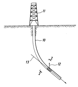
Attention is directed to Fig. 1 of the drawings. In
Fig. I a deviated well 10 extends from a drilling rig 11 which is
at tlle surface, either on l~nd or at se~. The deviated well 10
2 0 extends ~t some angle meaning that it deviates from the
vertical. A vertical reference direction is indicated by the
arrow 12. The direction of the well in that region is indicated
by tlle arrow 13. The angle between the lines 12 and 13 is the
angle of deviation. lt can be as much as seventy degrees or so.
Typically, at this stage of proceedings, the well is cased and the
casing is cemented in place. Locations along the cased well can
be determined by utilizing a casing collar locator (CCL) so that a
formation of interest can be located. The formation of interest
is in~icated generally by the numeral 14 in Fig. 2 of the
3 0 drawings.
~LS 90.043 4
4028~L
The formation 14 extends at an angle 15 with
respect to the horizontal reference line shown in Fig. 2 of the
drawings. The vertical reference 12 again is reproduced in Fig.
2. Thus, the vertical reference 12 defines the horizon which
serves as a reference. It is important to note that the
formation 14 includes formation bedding planes 16 which
extend with the formation. These define what is, loosely
speaking, formation grain. The formation grain makes it highly
desirable that perforations are formed parallel to the bedding
10 plane 16. It is generally desirable that the perforations formed
be precisely parallel. Obviously, this type of precision is not
essential but it is highly desirable that the perforations extend
approximately or close to the bedding plane angle. The
perforations 17 shown in Fig. 2 are almost parallel to the
formation bedding plane. This enables the perforations to take
advantage of the natural flow channels found in the formation
so that production is enhanced. As will be further understood,
Fig. 2 is taken through the formation and only two perforations
are shown, one extending up in the formation and the other
2 0 extending downwardly in the formation. It is desirable that
multiple formations be formed parallel to the perforations 17
shown in Fig. 2. They will all collectively be parallel to each
other and hence or ideally parallel to the bedding plane 16 of
the formation 14.
The circumstances in which the present procedure
is carried out should be noted. The present procedure is a
completion procedure. That is, the well has been drilled and it
has been determined that there is sufficient interest in
production that the well should be cased and the casing
30 cemented in place. Moreover, it is normally known in advance
what particular formation is the production zone, and
HLS 90.043 5
28
information about that zone is obtained. This information
includes the angle 15 which describes the angle of the
formation bedding plane with respect to the horizontal
reference, see Fig. 2. In other words, the angle 15 is known at
this juncture. Typically, a survey of the well 10 is also run and
this provides a map or chart of the path of the well. Thus, the
slant or deviation angle of the well is also Icnown in advance.
It is generally known that the zone has a specified thickness
also. Wi~h this information, the tool of the present d~isclosure is
10 then used to form the perforations which will be described.
Going now to Fig. 3 of the drawings, the tool of the present
disclosure is shown in a cased well. The description will
proceed from top to bottom. Fig. 3 is formed of several
sequential sections which are illustrated in sequence to provide
a full description of the apparatus.
The tool of the present disclosure is indicated
generally by the numeral 20. It incorporates a cable head
assembly for attachment to the wireline at 21. It is typically
run in the well by connection with a wireline which connects at
2 0 the cable head and suitable electrical connections are also
included. These communicate through the wireline and connect
to various components of the tool as will be described. The top
end of the tool incorporates a swivel 22, typically a purchased
item, which is in the preferred embodiment a pressure
balanced wireline swivel which cancels torque from the
wireline as it is reeled from the storage drum and extended in
the well 10. In addition to that, the tool sul~po, ls a navigadon
package 23 preferably containing a gravity operated pendulum
connecting with a potentiometer which provides a signal for
3 0 the surface. The signal indicates the angle of perforating shot
plane of the tool with respect to the vertical. In addition to
HLS 90.043 6
-
2040X8
this, the tool includes a casing collar locator 24. The CCL
detects the location of the casing collars to enable the
perforating gun assembly 20 to be located at the correct depth
in the well.
Continuing with the description of the perforating
tool 20, an axial passage 25 is noted. This is an electrical
pathway for conductors which extend through the tool from the
very top to the bottom. One conductor extends to the very
bottom of the perforating assembly 20 to operate a detonator
10 mech~nisln which will be described. That is preferably carried
at the lower end of the tool for reasons which will be set forth.
Passage 25 extends through a sub 26, and the sub has an axial
bore therethrough as mentioned which is countersunk t~
receive a mandrel 27. The mandrel 27 continues therebelow.
The mandrel 27 is surrounded by a skirt 28 at the upper end,
the skirt being appended to the sub 26 and formed integrally
therewith. These two members are preferably threaded
together and are joined when the tool is assembled. The skirt
28, however, terminates at the - lower end and supports an
2 0 abutting bearing assembly 29. The bearing assembly in turn
supports a spaced sleeve 30. The sleeve 30 is supported by a
similar bearing assembly 31 at the lower end. Both bearing
assemblies are locked in place. They permit the sleeve 30 to
rotate freely. The sleeve supports one or more rollers 32 for
freewheeling motion on an axle 33. There is a window cut in
the sleeve to enable the roller to extend outwardly. In the
preferred embodiment, there are two sets of rollers supported
by the sleeve at different elevations, and hence, they are
shown offset along the length of the tool. Moreover, the rollers
3 0 are duplicated. For instance, two sets of three or four rollers
typically will suffice. The sleeve is able to rotate in either
HLS 90.043 7
~0402
direction. The sleeve is rotatable, and thereby functions as a
type of cradle assembly for the tool. As described to this
juncture, the rollers contact the surrounding casing that makes
up the well borehole. It is not essential that the rollers contact
at all points around the circle which confines the tool within
the casing. Rather, the maximum diameter of the tool
measured at the rollers is something less so that the tool is able
to traverse locations where the casing is not perfectly round.
Moreover, the rollers 32 are sized so that they contact on what
10 might be termed the bottom side of the tool. Fig. 3 shows the
tool in a vertical posture, and this is the normal view one
would have of the tool when it is first placed in the well.
However, recall that Fig. 1 shows the well 10 to be deviated.
At this point, the roller on the left is on the low side of the tool
and tends to support the weight of the tool while the roller on
the right is on the high side and typically does not contact the
surrounding casing. This clearance enables the sleeve 30 to
rotate left or right. It also enables the tool to slide down the
cased well 10 supported on the wireline until it reaches the
20 depth of the formation shown in Fig. 2.
The mandrel 27 threads into an eccentric sub 35.
This has an offset enlargement 36 which is eccentrically
mounted. The eccentric weight 36 extends along the length of
the sub. It hangs to the low side when permitted to rotate.
The sub 35 rotates with the mandrel 27. The mass of the
eccentric 36 is suf~lcient to cause rotation. When rotation of
the mandrel 27 occurs, it rotates within the sleeve 30 which is
connected to it by the upper and lower bearing assemblies
previously described. The eccentric 36 thus hangs to the low
3 0 side. Again, recall that Fig. 3 shows the tool upright when in
reality it is positioned at an angle so that the left side of Fig. 3
HLS 90.043 8
z~
is the bottom side. The eccentric 36 is axially drilled with the
passage 37 which terminates at a larger ch~ ber 38 to enable
wiring communication through the tool. The eccentric is a
portion of the sub 35 and it is shaped with a circular external
surface. A shoulder 39 limits upward movement of a hollow
lock nut 40. The lock nut 40 is threaded for locking purposes.
This will be detailed below.
The lock nut 40 has a lower peripheral edge 41
which abuts a lock ring 42. The ring 42 is received in an
10 encircling groove 43 around the sub 35. Moreover, the sub 35
also abuts a shoulder 44 which is formed in an adjacent sub 45.
The sub 45 has an upstanding internally threaded skirt 46.
The lock nut 40 threads to the sub 45 at the threads on the
skirt 46. Moreover, when the lock nut 40 is threaded to move
upwardly, it disengages the lock ring 42. When the nut 40 is
rotated in the opposite direction and is forced downwardly, it
jams the lock ring 42 and forces the ring against the eccentric
sub 35 so that the eccentric sub 35 is jammed against the sub
45 and held in fixed relationship on the shoulder 44. The subs
2 0 35 and 45 are thus locked together by the nut 40 when it is
rotated to the down or locked position and they are free to
relatively rotate when the lock nut 40 is in the up position.
The lock nut 40 is controllably installed to
selectively fasten the subs 35 and 45 together so that they are
prevented from relative rotation. Rotation is desirable so that
the sub 45 can be rotated to a particular angle with respect to
the eccentric 36. The purpose of this will be more apparent on
description of the tool at the time of installing the shaped
charges.
3 0 The sub 45 is threaded to an elongate perforating
gun assembly 47. The gun 47 has an enclosure formed of an
HLS 90.043 9
0;~8~l.
elongate sleeve which is an axially hollow sleeve which
encloses one or more shaped charges pointing radially
outwardly. The sleeve is provided with thin wall scallops 48
aligned with the shaped charges forming perforations at the
circular scallops. The several shaped charges are supported by
a common assembly aligned in the sleeve enclosure 47. This
keeps all the debris after firing collected in the enclosing
hollow sleeve 47. Preferably, rows of shaped charges are
installed and they are aligned to fire in the same radial
10 direction. There are rows of charges, one which can be seen in
Fig. 3 and a duplicate or similar opposing set which form
perforations 180 out of phase. In other words, perforations
are made by the rows of shaped charges pointed in opposite
directions. The sleeve has interior space to support the
multiple shaped charges. As mentioned before, the passage 37
extends the connection pathway through the tool. The shaped
charges are connected with a detonator mechanisrn located at
the bottom of the perforating gun tool. The external sleeve,
being axially hollow, is able to receive and support the
2 0 necessary connections for rows of shaped charges. The
preferred embodiment preferably includes two sets of shaped
charges, the sets being positioned to form two opposing sets of
perforations.
The housing connects with another sub 50 and is
threaded to it in the same fashion as the sub 45 thereabove.
The lock nut 40 is duplicated by the lock nut 55. This engages
a simil~r ring 51 which causes the sub 50 to thread to and lock
with a second eccentric sub 56. The passage 37 in the upper
portion of the drawing is also extended at 52 through the sub
3 0 50 and again is extended at 53 through the eccentric sub 56.
Since the lock nut 55 operates in the same fashion as the lock
HLS 90.043 1 0
- 2~40283~.
nut 40, it is believed that the foregoing description can likewise
be applied to this lock nut so that it will be understood how the
eccentric sub 56 is controllably locked to the elongatc sleeve
supporting the several shaped charges.
The eccentric sub 56 is drilled with an offset
passage and supports a mandrel 58 which is similar in
construction and purpose to the mandrel 27 previously
mentioned. The mandrel 58 is threaded to the sub 56
thereabove. Thus, these two components move together as a
10 unit. A bearing assembly 59 is shown therebelow and supports
a surrounding sleeve 60 which is identical to the sleeve 30. It
extends downwardly to another bearing assembly 61. In turn,
this supports plural rollers 62 which are mounted on the
appropriate axles 63. This enables a duplicate set of rollers to
that shown at the top end of the tool to be positioned by the
sleeve 60 for rotation. Moreover, the sleeve is able to rotate,
thereby providing a mechanism whereby the sleeve operates
as a cradle which permits the equipment passing through the
center thereof to rotate. The upper sleeve 30 and the lower
2 0 sleeve 60 are similar in construction and operation. The lower
end of the mandrel 58 is threaded to an enclosed sub 65
having a chamber 66 for enclosing the detonation equipment.
The mandrel 58 thereabove is provided with the axial passage
64 which extends through it and connects with the chamber 66.
A conductor for firing is extended along the several passages
shown in Fig. 3 and is received in the chamber 66 where it
connects with the detonation equipment. In turn, the passage
also received the conductors extending from tbe detonator back
to the charges for operation of the charges.
3 0 Various and sundry seals are included to prevent
leakage of any fluid in the well into the tool. Thus, the axial
HLS 90 043 1 1
.
2040281
._
passage along the tool is sealed so that the firing
equipment is not subjected to the intrusion of well
fluid or elevated pressures.
The foregoing describes the structure of the
present apparatus. However, the operation should be
noted. This operation can be given best by an example.
For this purpose, assume that the well 10 has a region
which is a slant well which is inclined at a 45 angle
with respect to the vertical. Assume further that the
fracture bedding plane shown in Fig. 2 of the drawings
is at an angle of 30 with respect to the horizon.
This means that the perforations on one side of the
perforating gun assembly should be directed at an angle
of 60 with respect to the vertical and the opposite
set of perforations should be 180 out of phase because
they are located on the opposite side of the
perforating gun assembly. This is an angle of 30
which is implemented at the surface. It is implemented
by first installing the sub 45 onto the sleeve 47 which
houses the shaped charges within the sleeve behind the
scallops 48. After installation, and with the lock nut
40 loose, the eccentric 36 is moved relative to the
axis of the sleeve housing the shaped charges. As
shown in Fig. 3, the perforating gun will form
perforations which are perpendicular to the plane of
the paper. The lock nut 40 is loosened, the threaded
skirt 46 is rotated so that all the perforating guns
supported by the tool are aligned in the new position
relative to the eccentric 36. After that alignment has
been accomplished, the lock nut 40 is then tightened by
threaded engagement. This acts against the ring 42 and
accomplishes tightening. The same activity is repeated
at the lower end of the tool so the lock nut 55 is
likewise fastened. When the two lock nuts are threaded
up tight, the eccentric weights 36 and 56 hang to the
side at a
V 12
02
common azimuth with respect to the shaped charges supported
by the sleeve 47. Between the two eccentric subs, the sleeve
47 and enclosed shaped charges are mounted eccentrically.
The sleeve can be as short or long as needed; it is not
uncommon for the sleeve to be twenty feet long. In a longer
length, the greater portion of tool weight is eccentered. For
instance, in a 500 pound tool (with guns), as much as seventy-
five or eighty percent of the weight is eccentric. The
navigation package is turned on and its relative position to the
10 eccentric weight is recorded.
The tool is then lowered into the well borehole. The
CCL counts the casing collars as the tool travels downwardly.
The tool travels rather smoothly because it is equipped with
rollers, upper and lower rollers in particular, which enable it to
travel smoothly. As it passes through the various casing
collars, the depth of the tool in the well is determined. When it
reaches the requisite depth based on casing collar count in
conjunction with the schedule of pipe lengths involved in the
casing string, the cable is held so that the tool can no~ longer
2 0 travel. At this juncture, the navigation equipment forms an
output signal which is indicative of the shaped charges phase
orientation with respect to the vertical. Referring to Fig. 2, this
equipment measures the angle of the perforating gun assembly
with respect to the vertical reference 12. If this angle
coincides with the angle which was thought to be correct, then
the equipment has been determined to be at the right depth in
the well and at the right angle of phase orientation . Time is
permitted to pass so that the tool can rotate. Tool rotation
involves the rotor carriages at the upper and lower ends of the
3 0 tool. Recall the sleeves 30 and 60 which support the sets of
rollers. The rollers on the two sleeves contact the casing which
HLS 90.043 1 3
- ~ X~028
defines the well borehole, and permit the tool to rotate along
its lengthwise axis. This rotation is driven by the eccentrics
which extend to a common azimuth. Here, it must be noted
that the eccentrics are pointed in a particular direction when
the tool is first placed in the well borehole. At the surface,
however, the tool is vertical and the eccentrics are not free to
fall to the gravity side or down side. As the well deviates from
the vertical, and especially when it reaches a deviation of forty,
fifty or even seventy degrees, the eccentrics fall to the low side
10 of the well. This causes rotation of the entire tool. Rotation is
not resisted by the cable which is connected to the tool because
the tool ;ncludes the swivel mechanism 22 at the upper end
and that permits the tool to rotate in either direction without
bias and further permits it to rotate sufficiently that the
eccentrics fall to the down or bottom side. The two eccentrics
and perforating gun 47 thus move to the down side and define
the vertical line 12 shown in Fig. 2. When that occurs, the
shaped charges within the sleeve are then correctly positioned.
Recall from surface assembly that the sleeve has
2 0 been rotated with respect to the eccentrics. It is thus
positioned so that the perforations 17 shown in Fig. 2 are
formed as close as possible parallel to the formation bedding
plane. This enables the perforations to have greater length and
to extend deeper into the formation of interest, and to provide
the resultant production. At this juncture, the tool can then be
fired. Tbe sequence therefore has the first step of determining
that the tool is at the right well depth, then measuring the
angle of orientation of the tool which measurement is
compared bymeans of the navigation package with the
3 0 anticipated orientation. If a match is obtained, this indicates
the tool is at the right well depth and oreintation with respect
HLS 90.~43 1 4
20~0281
to the vertical reference. Time is permitted for the
tool to rotate inside the roller mounted cradles at the
upper and lower ends of the tool. If desired, while
monitoring the navigation package data and recording at
the surface, the tool can be raised and lowered gently
a few times, moving only a few feet on each stroke, all
for the purpose of permitting rotation. Rotation is
accomplished so that the perforating guns are then
correctly referenced to the vertical lines in Figs. 1
and 2. This then positions the perforating guns for
operation. A signal from the surface is transmitted
down the wireline. It travels through conductors in
the several passages through the tool to the chamber 66
at the lower end. The detonation equipment is located
in that chamber, and in turn, that forms a signal
producing detonation. That signal is conveyed to the
various perforating charges and they are fired by that
signal. After firing, the tool is retrieved on the
wireline. It travels easily out of the well borehole
because it is traveling in the slant well supported on
rollers. When it is in the vertical part of the well,
contact with the casing is somewhat incidental. It can
be retrieved quickly and at the surface, the sleeve and
spent shaped charges in the sleeve are discarded and a
gun assembly 47 is installed. If needed, the relative
angle of the shaped charge (when they are fired) is
adjusted by adjustment of the angular position of the
threaded skirt 46 with respect to the eccentrics. In
summary, the device can be readjusted so that each use
of the device can move to a different angular
direction.
While the foregoing is directed to the
preferred embodiment, the scope thereof is determined
by the claims which follow.
V 15