Note: Descriptions are shown in the official language in which they were submitted.
`` 2 ~ 3 3
Furniture unit for install~tion in a right-~ngled
corner of a room
The invention concerns a furniture unit according
to the preamble of the independent claim 1.
When fitting out kitchens, offices, laboratories
or such like, walls which together make up an angle of
eg. 90 should also be used as far as possible for the
installation of furniture. However, the corner space
often remains unused because the adjoining pieces of
furniture placed against the two walls would make
furniture which would fill out this corner space at
least partially inaccessible.
A furniture unit avoiding this inaccessibility,
for installation in a right-angled corner of a room, is
described in the patent CH-593 657. This prior art
furniture unit has two horizontally sliding built-in
units, the outer built-in unit being withdrawable from
the basic unit and pivotable around a vertical axis
from the corner of the room. The two sliding built-in
units are interconnected with levers such that when the
outer built-in unit is pivoted around the vertical
axis, the built-in unit in the corner is displaced
inside the basic unit horizontally in the direction of
the latter to the place originally occupied by the
built-in unit pivoted outwards. The built-in units
used in the prior art design each contain one sliding
element. The inside of the element is fitted with
storage components, for example, shelves or wire mesh
baskets to store the objects to be kept in the
furniture unit. The element may for example be made
from a wooden cabinet which is open at the front or
2~433
from a welded steel frame.
The prior art design of a furniture unit for
installation in the corner of a room has disadvantages
due in particular to the size and spatial dimensions of
the element. These disadvantages affect the assembly
of the arrangement above all, but also its flexibility
with regard to use in furniture of varying dimensions
and design. The element is designed as a spatially
relatively bulky component to be inserted into the pre-
assembled furniture unit, fixed there and connected
with the lever system. Due to inaccuracies in
production or distortion in the element occurring
during assembly, the guides may be warped. The
horizontally sliding built-in units can in turn become
awkward to move and thus restrict the functioning of
the furniture unit. Moreover, because of its
dimensions in particular, but also because of its lack
of flexibility and adaptability, the prior art
furniture unit is scarcely suitable for such
applications as envisaged eg. through sales via do-it-
yourself outlets.
The object of the invention is therefore to
provide a furniture unit for installation in a corner
of a room, production and assembly of which should be
significantly simplified and accelerated and wherein
the likelihood of warps in the horizontally sliding
built-in units should be excluded as far as possible.
In doing so, it is intended that even simpler
components than those of the prior art solution should
be used.
The object is solved according to the invention by
3 3
means of the features listed in the characterizing part
of claim 1.
It is also an object of the invention to design
the mountings used for the sliding device in such a way
that it is possible to use them in a variety of
differently constructed furniture. Thus the device
should for example be adaptable to the dimensions and
designs of built-in cupboards which vary according to
the standard of a particular country, or be able to be
used together with different cover panels such as e~g.
granite panels. This is achieved in particular by
means of the special design of the guide frame in the
first embodiment of the invention.
The invention is described by way of example below
in more detail with reference to the drawings in which:
Fig. 1 is a diagrammatic perspective view of a
furniture unit according to the
invention in the closed state,
Fig. 2 is a diagrammatic perspective view of a
furniture unit according to the
invention, whereby the outer built-in
unit is withdrawn and pivoted outwards,
Fig. 3 is a view of the sliding frame of the
outer built-in unit,
Fig. 4 is a perspective view of a first
embodiment of the inner built-in unit
with accompanying guide frame,
Fig. 5 is an enlarged side view of the first
2 ~ 3 3
embodiment shown in Fig. 4,
Fig. 6 is a perspective view of a second
embodiment of the inner built-in unit
with accompanying guide frame and
storage component,
Fig. 7 is the top plan view of a furniture unit
according to the invention (without
cover panel) as per the second
embodiment, the outer built-in unit in
withdrawn position; the broken line
shows the pivoted out position in
addition.
According to this invention, the built-in units
are essentially designed so that the storage components
can be suspended on one side into a flat frame after
all the other components have been assembled. This
sliding flat frame, referred to hereafter as the
sliding frame, is mounted on a similarly flat
horizontally sliding guide frame. In contrast to the
prior art solution which is fitted with an equivalent
lever system, the element is thus no longer designed as
one component with one spatial dimension.
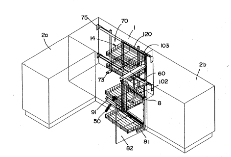
Fig. 1 shows a furniture unit according to the
invention. A basic unit 1, for example a wooden
element, is built into a corner of a room. Within the 30 basic unit there are built-in units 3, 4, each with a
number of storage components 14, although for reasons
of clarity, the inner built-in unit 3 is fitted with
only one storage component 14. The other storage
components 14 which can be used on the inner built-in
2 ~ 3 3
unit 3 and the outer built-in unit 4, are not shown.
Any other pieces of furniture 2a, 2b adjoin the basic
unit 1. Due to the proximity of the element 2a which
adjoins crosswise, the inner built-in unit 3 in a
standard furniture unit would not be accessible from
outside.
For this reason, CH-593 657 proposes a lever
mechanism allowing an obligatory displacement of the
inner built-in unit 3, when the outer built-in unit 4,
after having been withdrawn from the basic unit 1, is
then pivoted around a vertical axis. The present
invention also makes use of this prior art lever
arrangement. Fig. 1 shows the inclined lever 50 which
is mounted in such a way that when it cooperates with
the connecting lever 60, a kinematic chain is formed
via which is achieved a displacement of the inner
built-in unit 3 to the position accessible from
outside, when the outer built-in unit 4 is pivoted
around the vertical axis 100.
For this purpose the invention intends that the
flat sliding frame 80 of the outer built-in unit 4 is
mounted on a pivotable guide unit 90 such that it can
slide longitudinally. The pivotable guide unit 90 on
which is mounted the sliding frame 80 of the outer
built-in unit 4, is mounted on the side furthest away
from the inner built-in unit 3, and is connected in
turn with the basic unit 1 via the hinges 101 forming
the vertical pivot axis 100.
A flat guide frame 70 is mounted vertically for
the inner built-in element 3 at the back of the
furniture unit. This guide frame 70 has sliding tracks
3 3
whose purpose is to guide the horizontal displacement
of the sliding frame 120 of the inner built-in unit 3
The movements are coupled via the two levers 50, 60.
Fig. 2 shows the furniture unit according to the
invention in the state in which it is when the outer
built-in unit 4 is withdrawn from the basic unit 1 and
pivoted around the vertical axis 100.
Fig. 2 shows in the lower half of the drawing the
track component 91 of the pivotable guide unit 90 of
the outer built-in element 4, said pivotable guide unit
90 shown here in the position of being pivoted around
the vertical axis 100 by almost 90. It is obvious
that the sliding frame 80 and all elements affixed
thereto must be withdrawn from the basic unit 1 before
carrying out the pivot movement of the guide unit 90.
During this longitudinal displacement of the
sliding frame 80, the latter is carried both by the
track component 91 of the pivotable guide unit 90 and
by the track component 103 of the stationary support
unit 102. This stationary track component 103 can be
clearly identified in Fig. 2. It should also be
recognised that the pivot movement of the inclined
lever 50 is engendered in the way already described in
CH-593 657 by means of the track component 91 of the
pivotable guide unit 90. D~e to displacement to the
place originally occupied by the outer built-in unit 4,
the storage components 14 of the inner built-in unit 3
are now accessible from the front of the piece of
furniture. Finally, it can be seen in Fig. 2 that the
sliding frame 80 of the outer built-in unit 4 is
provided with preferably adjustable fixation means 81,
4 3 3
in order to attach a cover face 82 thereto.
Fig. 3 is a side view of the sliding frame of the
outer built-in unit 4 in the closed state of the
furniture unit, i.e. the sliding frame 80 is in a
position of ~eing pivoted and pushed inwards. The
drawing shows another possible form of embodiment of
the design of the pivotable guide unit 90 and the
guides for the sliding movement of the sliding frame 80
with respect to the guide unit. In contrast to the
emobodiment shown in Fig. 2, in which the stationary
support unit 102 is fitted with a track component 103,
in the example shown in Fig. 3, the upper track 83 of
the sliding frame 80 is guided solely via guide rollers
92 mounted on the pivotable guide unit 90. The
vertical part 93 of the pivotable guide unit 90 is
mounted opposite the stationary support unit 102 by
means of the two hinges 101.
There is a sliding roller 85 in the region of the
end of the lower track 84 of the sliding frame 80
facing the inside of the furniture unit, which sliding
roller rolls along the track component 91 of the
pivotable guide unit 90. At the opposite end, i.e. at
the end facing the front side of the furniture unit,
the pivotable guide unit 90 is provided with another
sliding roller 94, on which rolls the lower track 84 of
the sliding frame 80 when the latter is withdrawn from
the basic unit.
The track component 91 of the pivotable guide unit
90 is provided on its bottom edge with a sliding
element 95, which serves, in a manner known per se to
drive the pivot movement of the inclined lever 50.
2 ~ 3 ~
Fig. 3 shows clearly that when the sliding frame 80 is
withdrawn from the basic unit, the sliding roller 85
disposed at the corner of the sliding frame 80 is
displaced towards the sliding roller 94 which is
connected with the guide element 90, said sliding
roller 94 remaining at first stationary in relation to
the basic unit.
As already mentioned, various embodiments are
possible, particularly with regard to the construction
of the guides and mountings of the sliding frame 80.
Moreover, additional means may be provided to bring
about an obligatory coordination of the pulling out and
pivoting movements of the built-in unit.
Fig. 4 is a perpective view of the most important
components of the inner built-in unit. The sliding
frame 120 is formed essentially by the vertical struts
121 and the horizontal struts 123, 124. The vertical
struts 121 are each provided on their front side at the
same height with a number of hooks 122 which are
preferably disposed at the same distance to each other.
The storage components (not shown) are suspended on
these hooks after assembly has been completed. The
storage elements are for example, designed in the form
of flat wire baskets, dish-shaped or plate-shaped
elements. These are suspended in such a way on one
side of each sliding arm of the inner or outer built-in
unit that they form a right angle with regard to the
flat frame. In the case of the wire baskets suspended
on the hook-shaped fixation elements 122 shown in Fig.
4, the right-angled protrusion of the storage
components from the sliding frame is ensured by the
2~ 36~
lower portion of the storage components resting against
the frame. For this support it is of course necessary
that the storage components are of a certain height,
i.e. that there is a sufficient gap between the parts
cooperating with the hooks 122 and its lower portion.
Another embodiment for the fixation of the storage
components 14 against the respective sliding frame is
shown in Fig. 6. The respective sliding frame is
provided with bores instead of hook-shaped elements,
into which the respective fixation elements of the
storage component 14 are inserted. The principle of
such insertion is known per se and can be seen from the
diagram in Fig. 6. Naturally, the embodiment shown in
Fig. 6 of the fixation of the storage components 14
against the respective sliding frame can also be used
in the case of the embodiment of the sliding frame
shown in Fig. 4. In Fig. 3, in the embodiment of the
sliding frame 80 of the outer built-in unit, the latter
is provided with bores to engage for example storage
components according to the embodiment shown in Fig. 6.
Naturally, the embodiment for mounting the storage
components against the sliding frame, based on the use
of hook-shaped fixation elements according to Fig. 6,
can also be used in this embodiment example.
A basic prerequisite for the configuration
according to the invention of the respective sliding
frame as a flat component is that the storage elements
14 be suspended on one side on the respective sliding
frame. In addition to the range of mentioned
advantages of the solution according to the invention,
the different ways of fixing the storage components
2 ~ 3 3
ensures excellent handling and flexibility thereof.
Thus the storage components can simply be changed or,
in order to permit cleaning work, for example, they can
simply be removed. This results in simple and good
access to the built-in components.
The horizontal struts 123, 124 of the sliding
frame 120 which can be seen in Fig. 4, are fitted on
the back side with a number of guide rollers 125, 126,
127 whose purpose is to guide the longitudinal movement
of the sliding frame 120 against the rigid guide frame
70.
The rigid guide frame 70 comprises two struts 71
running at an appropriate distance from each other in
the horizontal direction, which serve as track for
rollers on the sliding frame 120. These tracks 71 are
interconnected at the rear by means of two vertically
running connecting struts 72. These connecting struts
72 are fitted on the underside with supporting feet 73
which can be affixed to the floor. They are preferably
provided with holes to allow the fixation of these
supporting feet 73 to the floor.
To fix the stationary guide frame 70 at the side,
the tracks 71 are provided at each end with support
arms 75. The support arms 75 end with flange plates
76, which in turn are preferably provided with bores
and are s~itable for affixation to a wall. The support
arms 75 are each inserted in a housing 74, so that the
former can be displaced in the direction of the tracks
71. The housings 74 are each fitted with a threaded
hole, in which there is an adjusting screw 77. The
inner cross-section of the housing 74 has a preferably
2~4~3
square cross-sectional shape which corresponds with the
outer cross-section of the support arm 75, and the
housings 74 are mounted preferably with a welded joint,
at the back and at each end of the track 71. Using the
described construction of the support arm it is
possible to adjust the latter, i.e. to adjust the
distance of the flange plates 76 with regard to each
end of the track 71. In this way, the guide frame 70
can be efficiently adapted to a wide variety of
arrangements.
The cross-section of the housings 74 preferably
corresponds to that of the connecting struts 72, or at
least their inner cross-section corresponds to the
outer cross-section of the support arm 75. Firstly,
this has the advantage that both parts can be
manufactured from the same semifinished product and
also provides the particular alternative of one pair of
support arms 75 also being able to be used in the
vertical direction inside the connecting strut 72. In
the same way as already described with reference to the
housings 74, there is a threaded hole in the upper
region of the connecting strut in order, in cooperation
with an adjusting screw, to ensure that the support arm
used in the upwards direction can be adjusted. This
allows a sufficient fixation of the stationary guide
frame 70 to be undertaken even if the conditions of
installation do not permit the horizontally disposed
support arms to be attached at both sides. In such a
case, the guide frame 70 could for example be fixed to
the qround, to a side wall (right or left) and to the
cover plate closing off the furniture unit at the top.
2 ~
Fig. 5 clearly shows the way in which the sliding
frame 120 is guided along the tracks 71 of the guide
frame 70 with the aid of the rollers 125, 126, 127
which are each present as a pair. This figure gives a
side vie~ of the components shown in the previous Fig.
4, although in Fig. 5, said components are shown in
their assembled, ready-to-operate state. Recognizable
again is the stationary guide frame 70, which is formed
essentially of the horizontal struts 71 acting as
tracks and the vertical connecting struts 72, ending at
the bottom in the form of the supporting feet 73. The
sliding frame 120 of the inner built-in unit is formed
by the struts 121, 123 and 124, the horizontally
running struts 123, 124 carrying the corresponding
sliding rollers 125, 126, 127. These are pivotably
connected with the corresponding strut in a known way,
for example by means of stationary axes. The pairs of
rollers 125, 126 are horizontally oriented, i.e. they
rotate around vertical standing axes. In the context
of their arrangement in the corresponding track 71 it
is clear that these pairs of rollers 125, 126 rotating
around vertical axes, assume the guiding of the sliding
frame 120 in the horizontal direction. It is obvious
that the diameter of the rollers 125, 126 has to be
slightly smaller than the inner width of the profile
71. This ensures that the horizon-;cal guiding of the
sliding frame 120 takes place with as little play as
possible and also that no frictional rubbing occurs
between the track and the roller.
The sliding frame 120 is guided vertically with
regard to the stationary guide frame 70 by means of the
pair of rollers 127. It can be seen that the roller
127 shown in Fig. 5 is vertically disposed, i.e. it
rotates around a horizontal axis which is connected
with the lower horizontal strut 124. The roller 127
rolls along the upper surface of the lower track 71.
The assembly of the sliding frame 120 on the guide
frame 70 should preferably take place before mounting
the latter inside the basic unit in such a way that the
sliding frame 120 is pushed up by one end of the tracks
71 onto the latter. However, if this is not possible,
it is certainly also possible to assemble the sliding
frame 120 by pushing the rollers of one side of the
sliding frame 120, those of the left side, for example,
onto the corresponding, ie. also the left end for
example of the tracks 71 and by subsequently moving the
sliding frame mounted on one side to the other end, ie.
the right end of the guide frame 70 and then there
pushing the rollers of the other side of the sliding
frame from the appropriate side onto the tracks 71 of
the guide frame 70.
Fig. 6 shows another form of embodiment regarding
the design of the inner built-in unit comprised of for
the most part flat components. In contrast to the
previously described embodiment whereby the sliding
frame of the inner built-in element is guided by means
of a stationary guide frame disposed vertically in the
rear region of the furniture element, in the embodiment
now to be described, the guide frame is disposed
horizontally in the upper region of the furniture
element. The guide frame 7 consists of a pair of
tracks 7b, which are interconnected by means of
connecting struts 7a. The sliding frame 12 is designed
2 ~ 3
14
as a two-part unit, consisting of a carriage 12a and a
carrier frame 13, on which the storage components 14
are suspended.
The carriage 12a which can be displaced along the
tracks 7 via sliding rollers 15, consists of a frame
formed from a pair of longitudinal struts 16 and
transverse struts 17 and a diagonal strut 17a, with
vertical struts 18 extending downwards from the back
edge of said frame. The bottom end of the vertical
struts 18 is connected by means of support struts 19
with the front portion of the frame, i.e. with the
front portion of the transverse struts 17, in order to
take up the bending moments acting on the vertical
struts 18. The vertical struts 18 of the carriage 12a
are formed preferably from L-profiles and welded with
the frame formed from the longitudinal and transverse
struts 16, 17. The vertical struts 18 are each
provided in their upper portion with a bore 20 running
in the longitudinal direction of the track 7b. Support
pins 21 are each connected, for example soldered,
rigidly with the upper end of the carrier frame 13 of
the inner built-in element. The distance between the
two vertical struts 18 is such that the carrier frame
13 just has room between the L-profiles. The support
pins 21 engage with the bores 20 in the vertical struts
18 after the carrier frame has been assembled.
To assemble the carrier frame 13 it is pressed
together in the open, upper portion to such an extent
that the outer ends of the support pins 21 can be
inserted from the inside into the bores 20. When the
pressure on the carrier frame 13 is released, it
2 ~ 3
springs back and now rests on the support pins 21
mounted in the bores 20 and its position is
simultaneously fixed by the L profiles of the vertical
struts 18. The back sides 18a of the L-profiles in
particular prevent the hanging carrier frame from
tilting backwards.
Fig. 7 shows a top plan view of a furniture unit
according to the second embodiment of the invention,
the cover plate of the furniture having been removed.
The drawing shows with the broken line the c~ndition
where the inner built-in unit 3 is in place and the
outer built-in unit 4 is withdrawn from the basic unit.
In the upper portion the horizontally disposed
stationary guide frame 7, the carriage 12a and the way
in which the levers 50, 60 operate can be seen. The
inclined lever 50 is pivotable around a centre of
rotation 51 fixed on the floor of the basic unit and
designed as a guide 52 on the side which is connected
with the track portion 91 of the pivotable guide unit
90. A slide component 95 connected with the track
component 91 slides in this guide 52. At the end lying
on the other side of the centre of rotation 51, the
inclined lever 50 is connected with a connecting lever
60, which in turn is attached to the sliding frame of
the inner built-in unit.
The dot-dash lines show the position which the
components assume, in particular the lever system, when
the outer built-in unit 3 is pivoted around the
vertical axis 100 thus displacing the inner built-in
element to the then free space.
Use of the invention shown permits realization of
2~ 3
16
a furniture unit for installation in a corner of a room
with simpler means and less components than before.
The individual parts provided for by the invention are
suitable for a variety of embodiments and dimensions of
the furniture, the assembly of the built-in units
consisting essentially of flat parts is considerably
simplified and the operating reliability, i.e.
reliability with regard to jamming and blocking of the
movable elements is significantly increased.