Note: Descriptions are shown in the official language in which they were submitted.
2 ~ P~j
The present invention relates to the dry
end or dryer section of a machine for the manufacture
of a fibrous web, particularly a web of paper. In
particular, the invention concerns a dry end of the
type which is formed exclusively of so-called single-
screen dryer groups. Dry ends of this type are known
from the following publica~ions.
1. Journal "Wochenblatt fur
~apier~abrikation", ~o. 22, 1988, page 6.
2. WO 90/01580, corresponding to U.S~
application 230,627, filed August 10, 1988~
3. WO 90/02225, corresponding to U.S.
application 235,394, filed August 23, l9a8.
~ hese publications disclose that the dryer
cylinders can be arranged either in at least
; : approximately horizontal rows or in at least
appro~imately vertical rows at leas~ over the greater
: part of the dry end. It is further known that to
subdivide such a dry end into several dryer groups,
wherein each dryer group comprises a plurality of
heatable dryer cylinders, a plurality of guide rolls
25 and a support belt which presses the web which is to be
dried against the dryer cylinders.
: :
. . .
: `
.
From above Publication l., it is known to
provide single-screen dryer groups exclusively ~etween
the press section and the calender of the paper
machine. However, there are also paper machines in
which a dry end consisting exclusively of single-screen
dryer groups extends from the press section up to a
size press or a similar intermediate station, or from a
size press to a calender.
It is further known from such publications
that the bottom side of the web always comes into
contact with the dryer cylinders in the last dryer
group. In this way, the web travels in the downward
direction, in particular, from the last dryer cylinder
in the downward direction. In this way, in case of any
disturbance, the web can be easily removed in the
downward direction into a broke pulper.
From above Publications 2. and 3., it is
known that a tip cutter must be installed at the end of
the dry end. As long as the web travels into the broke
pulper, the tip cutter can cut a narrow edge strip from
the web. This strip then serves for threading the web
into the following treatment stations, for instance
calender and reel, or size press, or the like. A free
stretch or draw of web is formed for such a tip cutter
by means of a special arrangement of rollers, since
upon the cutting of the tip, the web must be free of
the support belt which otherwise travels with the web.
In Publication 2., the free stretch or draw
of web is formed at the place of separation between the
next-to-the-last and the last dryer groups, and
therefore at a place where the web is still not
completely dry. Thus, there is a danger that the web
will tear upon the cutting of the tip. On the other
hand, if necessary, use can be made of the possibility
of controlling the we~ tension up~n the cutting of the
tip, by changin~ the difference in speed between the
two dryer groups.
In Publication 3,, the free stretch or draw
of the web is formed within the last group of dryers,
preferably between the last two dryer cylinders, and
therefore at a place where the web is completely dry.
Thus, the web only rarely tears upon the cutting of the
tip. Between the last two dryer cylinders, there is a
reversing roll with which the support belt comes into
direct contact. In addition, a web guide roll is
arranged below this re~ersing roll. The web travels,
free of the support belt, from the re~ersing roll to
the web guide roll and from the guide roll back to the
reversing roll so that two free stretches of web are
present. The aforementioned tip cutter is arranged on
one of these two free stretches or draws of web. With
this arranqement, there is the danger that upon tearing
of the web or upon some other unstable operating
condition, the web will wind up on the web guide roll.
Furthermore, this has the disadvantage that two free
stretches of web are present, althou~h only a single
free stretch of web is necessary for the tip cutter.
The danger of tearing, which is always present at each
free stretch of web, is therefore unnecessarily
increased.
SUMMARY OF THE I NVENT I ON
The object of the present invention is so
to develop a free stretch of web for a tip cutter in a
dry end of the aforementioned tyFe that the danger of
the web tearing and wrappin~ around a roll is at least
considerably reduced or preferably entirely eliminated.
In an apparatus for achieving this object,
in a selected dryer group, out of a plurality of dryer
groups, in which dryer group it is desired to arrange
the tip cutter, an auxiliary quide roll is arranged
between a selected dryer cylinder and an adjacent
reversing roll. Only the support belt travels over
this auxiliary guide roll while a free stretch or draw
of web extends between the selected dryer cylinder and
the adjacent reversing roll. The tip cutter can be
arranged on the free stretch of web. It is essential
that the web not come into direct contact with a guide
roll in the region of the tip cutter. This avoids a
danger of the web winding around a roll. Furthermore,
only a single, relatively short, free stretch of the
web is present. Accordingly, the danger of tearing of
the web is very substantially reduced.
The so called selected dryer group is
preferably the last dryer ~roup of the dry end along
the path of web travel. From this selected dryer
group, the web continues further to a subsequent
treatment station, for instance a calender, a size
press, or the like.
The apparatus of the invention can be used
in two different arrangements. In one arrangement, the
"selected dryer cylinder" is preferably the next-to-
the-last dryer cylinder o the selected dryer group.
In this case, the web of paper travels from the
selected dryer cylinder, after which it is separated
from the support belt, then over the free we~ path to
the reversing roll, where it again meets the suppart
'
.
..
belt, and from the reversing roll, together with the
support belt, in general to the following dryer
cylinder which is preferably the last dryer cylinder of
the selected dryer group. Instead of the following
dryer cylinder, however, any other following guide
roll, or cooling roll, or the like can be present.
In another arrangement of the apparatus,
the selected dryer cylinder is preferably the last or
next-to-the-last dryer cylinder of the selected dryer
group. In this case the web travels, for instance,
from a preceding dryer cylinder or from a preceding
guide roll together with the support belt to the
preceding reversing roll which precedes the selected
dryer cylinder. At that reversing roll, the web and
the support belt are separated. The web travels
separated from the support belt from the reversing roll
directly in a free stretch of web to the selected dryer
cylinder so that the tip cutter can be arranged here.
The support belt, free of the web of paper, travels
from the reversing roll over the auxiliary guide roll
ànd then to the selected dryer cylinder where it again
meets the web.
In order for the web to be pressed by the
support belt against the cylinder shell around the
largest possible part of the circumference of the
selected dryer cylinder, an additional auxiliary guide
roll can ke provided for the we~ in the vicinity of the
selected dryer cylinder.
In an alternative arrangement of the
apparatus for achieving the desired purpose, the
selected dryer group is divided into a first subgroup
and a second subgroup. In this way, the number o
- 6 - ~}~!
support belts and the number of required tensioning and
regulating rolls is increased. On the other hand,
however, this has the known advantage that the web
tension in the region of the tip cutter can be adapted
to specific prevailing requirements.
Further details of the various arrangements
as well as further embodiments of the invention and
examples are explained below on basis of the drawings.
BRIEF DESCRIPTION OF THE DRAWINGS
Fig. 1 is a a diagrammatic side view of a
dry end or dryer section of a paper making machine with
horizontal cylinder rows, with a free stretch of web
for a tip cutter.
Fig, 2 shows a detail of Fig. 1 with a
modified arrangemen~ of a tip cutter.
Figs. 3 to 5 show further possible variants
for the arrangement of the tip cutter.
Fig. 6 shows a dry end in which the dryer
cylinders are arranged in predominantly vertical
cylinder rows, also with a free stretch of web for the
arrangement of a tip cutter.
D~SSC~IPTION OF HE PR~FERRED EM~3ODIMENTS
T~e dry end or dryer section of a paper
making machine shown in Fi~. 1 comprises fiYe dryer
groups I through V. For simplifying the showing, each
dryer group i~ shown with only three or four dryer
cylinders. Actually, there are usually approximately
twice as many dryers in each group. In the first dryer
group 1, an endless web support belt 10, e.g. in the
form of a felt, passes over the upper circumferential
regions of each of the dryer cylinders ll to 13 and,
then following each dryer cylinder, over a respective
2 ~
reversing roll 1~ to 16, and then over guide rolls 17
back to the cylander 11.
In the second dryer group II, an endless
support belt 20, e.~. a felt, passes over the lower
circumferential re~ions of each of the dryer cylinders
21, 22 and 23 and then over respec~ive reversing rolls
24 to 37 and over guide rolls 28 back to the first
reversing roll 24.
The dryer groups III and IV are developed
substantially in the same way as the dryer groups I
and II.
Four dryer cylinders 31 to 34 are provided
in the dryer group V. The endless, web support belt 30
travels over the upper circumferential regions of each
of these dryer cylinders and then over the respective
reversing rolls 35 to 38 and guide rolls 39 back to the
first re~ersing roll 35. The reversing rolls 14-16,
24-26 and 35-38 are prefera~ly developed as suction
rolls, represented symbolically by a black dot.
The paper web 9 which is to be dried has a
top and a bottom surface. In dryer groups I, III
and V, the bottom of the we~ directly co~tacts the
dryer cylinders, while the top of the web directly
contacts the aryer cylinders in the drying groups II
and IV. At the outlet end of the dry end, the paper
web 9 leaves the last dryer cylinder 34 in the downward
direction and passes over a paper guide roll 40 to a
further treatment station, not shown.
In Fig. 1, the fifth or last dryer group V
is the so-called "selected dryer group. n Within the
dryer group V, the next-to-the-last dryer cylinder 33
is the so-called "selected dryer cylinder.~ setween
2~
-- 8 --
the selected dryer cylinder 33 and the following
reversing roll 38, an auxiliary guide roll 41 is
arranged. The support belt 30 sep rates from the wsb
at the selected dryer cylinder 33, and then travels
from the cylinder 33 without the paper web 9 on the
belt, directly to the auxiliary guide roll 41. From
the guide roll 41, the belt 30 goes to the reversing
roll 38. Meanwhile, the paper web 9, free of the
support belt 30, travels directly from the dryer
cylinder 33 to the reversing roll 3a. There, the paper
web 9 and the support belt are again brought together.
A tip cutter, arranged along the free stretch or open
draw of the web, is indicated symbolically by an
arrow S. On the travel path of the support belt from
the reversing roll 3a to the following last dryer
cylinder 34, a known web stabilizer ~2 is arranged on
the inner side of the support belt for establishing
dependable adherence of the paper web 9 to the support
belt 30,
In Fi~ 1, th~ paper web 9 moves in the
downward direction through the free path length from
the cylinder 33 to the reversing roll 38. ~his has the
advanta~e that in the ev~nt of a tear of the web,
particularly upon the entry into action of the tip
cutter S, the broke can be discharged downward over the
shortest path.
~owever, a differ2nt arrangement is
possible, as shown in Fig. 2. In that case, the last
two dryer cylinders are 33' and 34'. The last dryer
cylinder 34' is now the ~selected dryer cylinder.~ The
support belt in this case travels from the preceding
dryer cylinder 33' together with the paper web 9 to the
2~1.
reversing roll 38. After the roll 38, the support belt
30 separates from the web 9 and travels over the
auxiliary guide roll 41' to the selected dryer cylinder
34'. The paper web 9 travels from the re~ersinq roll
38 on a direct path, free of support b~lt 30, to the
last dryer cylinder 34' where the web meets the support
belt a~ain. The tip cutter S is therefore now arranged
on an upward traveling stretch of open draw of the web
rather than on a downward stretch as in the arrangement
of Fig. 1.
In order that ns pressure buildup takes
place in the pocket which is present on the reversing
roll ~8 between the cylinder 33' and the auxiliary
guide roll 41', a deflecting ledge for the oncoming air
boundary layer, supported by a beam 43, is arranged at
the place where the support belt moves of f the
cylinder 33'.
Fig. 3 shows another variant of the
arrangement shown in Fig. 1. The reversing roll 38l
and the auxiliary guide roll 41 are both at a somewhat
greater distance from the horizontal centra} plane of
the dryer cylind~rs 33 and 34, than in the embodiments
of Figs. 1 and 2. This placement of the rolls 38' and
41 defines a space for an additional auxiliary guide
roll 44 which assures that the support belt 30 and the
paper web 9 move jointly off the dryer cylinder 33. At
this place, there is a web stabilizer 45 which draws
the paper web 9 against the support belt 30 at the
place of removal. In Fig. 3, the reversing roll 38' is
not developed as a suction roll but as a fluted roll
without suction means. Therefore, an auxiliary device,
which is not shown, for instance, a cable guidance, a
-- 10 --
blast nozzle, or the li~e, is necessary upon the
threading of the paper web into the dry end to deflect
the oncominq tip of the edge strip upward to the dryer
cylinder 34. In Fig. 3, however, differing from the
showing, the reversing rall 38' can als~ be developed
as suction r~ll.
In Fig. 4, the last dryer group V' is
divided into a first subgroup Va which has a first
support belt 30a, and into a second subgroup Vb which
has a second support belt 30b. The first support belt
30a travels from the last dryer cylinder 33a of the
first subgroup ~a together with the web 9 to a last
reversing roll 38a which is developed as a normal guide
roll without suction means. From this reversing roll
38a, the first support belt 30a travels via guide rolls
39a bac~ to the start of the first dryer subgroup Va.
The second support belt 30b comes from the ordinary
guide rolls 39b, 39c to the reversing roll 38b of the
second subgroup Vb, comes together there with the paper
web 9 and deflects the paper web upward and brings it
to the solP dryer cylinder 34b of the second subgroup
Vb. In order to be able to keep the distance between
the dryer cylinders 33a and 34b small, the two
reversing rolls 38a and 38b are arranged one above the
other in the poc~et T. That poc~et i~ defined and
surrounded by the web passing between the dryer
subgroups. The clear space between the cylinders 33a
and 34b is small, about the diameter of ~he one
reversing roll 38a at the bottom of the pocket T.
Furthermore, between~the two reversing rolls 38a and
38b there is provided an auxiliary guide roll 46 which
feeds the second support belt 30b to the bottom
-- 11 --
reversing roll 38b of the second subgroup Vb. The
reversing roll 38b is developed as a suc~ion roll. A
few web stabilizers (without reference numbers) are
also shown diagrammatically.
The following modifications are possible.
The second subgroup Vb may have not only one but two or
more dryer cylinders and, accordingly, additional
reversing rolls. The last reversing roll 38a can lie
in the bottom o~ the pocket T and be develaped as
suction roll. The reversing roll ~8b can lie above the
auxiliary guide roll 46 and havs a small suction zone
at the place where the web 9 coming from below combines
with the second support belt 30b.
In all cases the web of paper 9 extends,
without contact with one of the support belts, from the
one reversing roll 38a to the other reversing roll 38b
completing the poc~et T. A tip cutter S is again
arranged on this free stretch or open draw of the web.
Xowever, the configuration of either FigO 4 or Fig. 5
can also be used without a tip cutter as a separation
of the two adjacent dryer groups, with the same side of
the web coming into contact with the dryer cylinders in
both dryer groups. This type of group separation is
more easily controlled, for instance, in the event of a
tear of the web, than the configura~ion in accordance
with Fig. 5 of U.S. Patent 4,359,827 or Fi~. 1 of U.S.
Patent 4,625,430.
If, as shown, a tip cutter S is present,
then the lower side of the web must come into contact
with the dryer cylinders 33a and 34b in both subgroups
Va and Vb. In other words, the dryer cylinders lie on
top in both subgroups Va and Vb. This is the same as
~ ~ ~.5~ ?
-- 12 --
in Fig. l where the dryer cylinders of dryer groups I,
III and V lie on the top while the dryer cylinders of
dryer groups II and IV lie on the bottom.
With the arrangement in Fig. 4 as a typical
5 example, the dry end can be di~ided into dryer grou~s
as follows:
Dryer group I: five upper cylinders,
Dryer group II: six lower cylinders,
Dryer group III: seven upper cylinders,
Dryer group IV: seven lower cylinders,
Dryer group V:
First subgroup: seven upper cylinders,
Second subgroup: one upper cylinder
Total number of dryer cylinders: 33.
In contrast to this, with the arrangement
of a tip cutter in acçordance with above noted prior
art Publication 2. again as an example, the following
division into groups would be necessary:
Dryer group I: five upper cylinders
Dryer group II: five lower cylinders
Dryer group III: five upper cylinders
Dryer group IV: five lower cylinders
Dryer group V: six upper cylinders
Dryer group VI: six lower cylinders
Dryer group VII: one upper cylinder
The total number of dryer cylinders would
again be 33. With this arrangement, therefore, an
additional support belt and the corresponding yuide,
tensioning, and regulating rolls would be necessary.
A group division with a tip-cutter
arrangement in accordance with Figs. l to 3 would be
even more favorable than with Fig. ~, namely, for
instance, the following;
2 ~ a ~
- 13 -
Dryer group I: five upper cylinders,
Dryer group II: six lower cylinders,
Dryer group III: seven upper cylinders,
Dryer group IV: seven lower cylinders,
Dryer group V: eight upper cylinders.
Here, as shown in Fig. 1, only five support
belts are necessary. The total number of dryer
cylinders would again be 33.
Fig. 4 fur~hermore diagrammatically
indicates that not only the dryer cylinder 34b but also
one of the guide rolls and preferably the guide roll
39c directly following the cylinder 34b is provided
with a dri~e. The two drives can, as shown7 be
connected to each other by gears 47, 48, 49. This
assures that even in the case of only a single dryer
cylinder 34b in the second subgroup Vb, the web tension
in the free web portion always has the desired value,
for instance, even if the web should tear between the
dryer cylinder 34b and the following units. Instead of
the guide roll 39c being driven, the reversing roll 38b
could also be drivenc
~ he arrangement in Fiq. 5 differs from the
one in Fig, 4 substan~ially only in the fact that the
auxiliary guide roll 46' is developed as a multi-member
roll, for instanee, as a spreading roll. Such a
spreading roll re~uires less space than an ordinary
: guide roll~ Furthermore, blast nozzles 50 are
indicated in Fig. 5 on the fPee web section. Those
nozzles guide the oncoming tip of the edge strip
dependably toward the suction roll 38b upon the
th~eading of the web 9 into the dry end. Instead of
using the blast nozzles 50, airfoil elements utilizing
2 ~
the Coanda effect or similar means could also be
pro~ided.
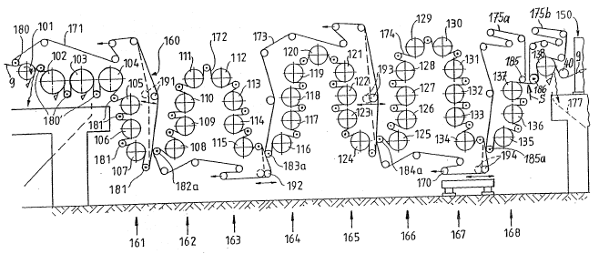
The dry end or drying section shown in Fig.
6 comprises a first horizontal row of cylinders 160 and
a total of eight su~stantially vertical dryer cylinder
rows 161-168 connected one after the other in the path
of web travel. At the right-hand end o~ Fig~ 6, one
can note a part of a calender 150 which follows the dry
end. It can be seen that, by the arran~ement of the
greatest part of the dryer cylinders 105-138 in
vertical rows, the length of the dry end is
substantially shorter ~han with an ordinary arrangement
of dryer cylinders in horizontal cylinder rows.
The first dryer group in Fig. 6, formed of
the cylinder rows 160 and 161, has an endless support
belt 171O It first travels over a suction guide roll
180 where the support belt takes the web 9 over from
the press section and feeds it to the first dryer
cylinder 101. From here, the support belt 171 and the
paper web travel to~ether in succession over the
reversing suction guide rolls 180' and 181 and the
cylinders 102, 107, with the lower side of the web
contacting the cylindersO From the lowermost suction
guide roll 1~1, the web is transported by the support
belt 171 in the direction toward the second dryer group
162~163.
As a whole, the dry end shown in Fig. 6 has
five dryer groups. Each group has its own respective
suppor~ belt 171-175. The guide rolls for these
` support bel~s 171-1~5 are only diagrammatically shown:
an ordinary guide roll as a plain circle, a suction
guide roll as a circle with a dot, and a tensioning
.' ~ ' ~' -.
roll as a circle with a single arrow, for instance,
roll 170. Some of the ordinary guide rolls 191-194 are
provided with a double-ended arrow. This means that
they are substan~ially displaceable horizontally.
The two vertical cylinder rows 162 and 163
together form a double row dryer group, i.e. the eight
cylinders 10~ have a common support belt 172. Thi~
conducts the web to be dried, starting from a pickup
roll la2a, first upward over the cylinders 108-111 and
then downward over the cylinders 112-115. In this
entire dryer group, the upper side of the web always
comes into contact with the cylinders.
In similar fashion, the two cylinder rows
164 and 165 form, together with an upper middls dryer
cylinder 120, another double row dryer ~roup having a
common support belt 173. That belt takes over the web
by means of a pickup roll 183a and conducts the web,
first upward over the cylinders 116-120 and then
downward over the cylinders 120-124. In this
connection, the lower side of the web always comes into
contact with the dryer cylinders as in the first dryer
group 160/161. ~his is followed by another dryer group
which is formed of the two cylinder rows 166-167 and
has the support belt 174. The construction of this
dryer group is practically identical to that of the
second dryer group 162J163, except that there are two
more cylinders. The last four dryer cylinders 135-138
form a final dryer group 168.
The web 9 travels from ~he last cylinder
138 freely and without support over a paper guide roll
40 into the calender 150. It is important that the
last dryer cylinder row 168 be traversed by the web in
~ 3
- 16 -
the upward direction and that the uppermost dryer
cylinder 138 of this row lies closer to the calender
150 than the other dryer cylinders 135-137. This
causes the finally dried web to discharge in the
downward direction from the last cylinder 138. If the
web now temporarily does not pass further to the
calender 150, it can drop down freely and is conducted
~urther over an obli~ue wall 177 into a broke pulper,
not shown.
The last dryer group 168 is again divided
into two subgroups. The first sub~roup comprises the
dryer cylinders 135-137 and has a support belt 175a.
The second subgroup has only a single dryer cylinder
138 and one support belt 175b. Paper web 9 and support
belt 175a travel first from the last dryer cylinder 137
of the first subgroup jointly to an ordinary guide roll
I85. From here the support belt 175a travels back to
the pickup roll 185a while the paper web 9 travels
freely to the first and sole reversing roll, the
suction guide roll 186 of the second subgroup. A tip
cutter S is again arranged on this free stretch of web.
~t the reversing roll 186, the paper web 9 comes
together with the support belt 175b, which conducts it
to the last dryer cylinder 138.
Although the present invention has been
described in connection wi~h a plurality of preferred
embodiments thereof, many other variations and
modifications will now become apparent to ~hose skilled
in the art. It is preferred, therefore, that the
present invention be limited not by the specific
disclosure herein, but only by the appended claims.