Note: Descriptions are shown in the official language in which they were submitted.
NE-335
2040572
TITLE OF THE INVENTION
2 "Cordless Key Telephone System Capable of Quickly Answering
3 Incoming Calls"
4 BACKGROUND OF THE INVENTION
s The present invention relates to a cordless key telephone system.
6 Cordless key telephone systems have been in use today replacing
7 wired key telephone systems as they considerably reduce the amount of
8 cables and wires laid on office floors the arrangement of which must be
g altered to meet current needs of working environment. The system
includes a main controller which is coupled to the public or private
11 switched telephone network via subscriber loops to receive incoming calls
12 and originate outgoing calls. The floor space which the system covers is
13 divided into several service areas. One or more access units are located in14 each service area and coupled to the main controller to exchange control
signals with it. In response to an incoming call, the main controller selects
16 one access unit for each service area and sends an alert signal to it. Each17 selected access unit then broadcasts a recurrent sequence of alert signals
18 respectively containing the identifiers of all standby cordless stations to19 elicit a response therefrom. Each standby cordless station responds to
20 the alert signal addressed to it by returning an acknowledgment signal
21 containing in it the own station identifier as well as the system identifier.22 Each selected access unit waits until it receives the acknowledgment
23 signals from all standby cordless stations and communicates this fact to
24 the main controller. The main controller waits for this communication
25 from each selected access unit to return a proceed-to-assign signal to
26 allow it to broadcast a channel assignment signal to switch the standby
27 cordless stations to an assigned speech channel on which ringing signals
28 will then be transmitted. If this communication is not received within a
29 prescribed timeout period, the main controller automatically sends the
2040572
74924-10
proceed-to-assign æignal to each selected access unit. When one
of the cordless station goes off hook, this fact is signaled by
the associated access unit to the main controller, whereupon it
establishes a connection between the network and the accesæ unit
from which the off-hook condition is signaled.
Since the cordless stations may roam across the
boundaries between the service areas of the æystem and since the
access units have no way of knowing this fact, the timeout period
for receiving acknowledgments from all stations often expires,
resulting in a delayed action for answering an incoming call.
In addi~ion, it i8 the usual practice to include a
battery savings circuit in the cordless stations. Upon completion
of an incoming call to a certain standby cordless station, the
ol;her standby cordless stations are automatically switched to the
battery savings mode. If another incoming call is received
immediately following the previous call, however, all other
cordless stations are in their battery savings mode and there is
an inevitable delay in alerting the stations until their power
supplies are turned on again.
2 O SUMMARY OF THE INVENTION
It is therefore an ob~ect of the present invention to
provide a cordless key telephone system which is capable of
answering incoming calls without wasting time.
According to one aspect, the present invention provides
in a cordless key telephone system having a plurality of access
units divided into groups corresponding respectively to service
areas for broadcasting radio signals on a two-way control channel
2040572
-
74924-10
or on an assigned two-way speech channel, a plurality of cordless
stations, and a main controller coupled to a switched telephone
network for selecting one of the accesæ units for each of said
service areas in response to an incoming call from said network
and transmitting a first alert signal to the selected access
units, a method comprising the steps of: a) receivinq said first
alert signal and, in response thereto, broadcasting from the
selected access units a recurrent sequence of second alert signals
over the control channel, the second alert signals respectlvely
identifying standby cordless stations; b) receiving the second
alert signal and, in response thereto, transmitting an
acknowledgment signal over the control channel from each cordless
station if the received second alert signal identifies the
cordless station; c) receiving the acknowledgment signal and, in
response thereto, transmitting a copy thereof from each of the
selected access units to said main controller; d) receiving said
copy of the acknowledgment signal from the selected access units
and, in response thereto, transmitting a proceed-to-assign signal
from said main controller to ~aid selected access units if the
number of the received copies of the acknowledgement si.gnals is
equal to the number of all standby cordless stations; e) receiving
said proceed-to-assign signal and, in response thereto,
broadcasting a channel assignment signal over the control channel
from said selected access units, said channel assignment signal
identifying said assigned speech channel; f) receiving said
channel assignment signal and, in response thereto, transmitting
an end-of-switching signal over the assigned speech channel from
2040572
74924-10
one of the cordless stations which are located in each of said
areas; g) receiving said end-of-switching signal and, in response
thereto, broadcasting from each of the selected access units
ringing signals over the assigned speech channel, the ringing
signals respectively identifying the cordless stations which have
transmitted said acknowledgment signals; h) receiving the ringing
signal and, in response thereto, generating a ringing tone in each
cordless station if the received signal identifies the cordless
station and allowing an off-hook signal to be transmitted over the
assigned speech channel from a replying cordless station; i)
receiving the off-hook signal and, in response thereto,
transmitting a copy thereof from one of the selected access units
to said main controller; j) returning a turn-on signal from the
main controller as a response to said copy of the off-hook signal,
said turn-on signal identifying the replying cordless station;
k) receiving said turn-on signal and, in response thereto,
broadcasting a copy thereof from said access unit; and 1) causing
said replying cordless station to receive said copy of the turn-
on signal and establish a speech circuit thereof.
Since the proceed-to-assign signal is transmitted from
the main controller to the selected access units at the moment
when acknowledgment signals from all standby cordless stations are
received by the main controller, the time taken to answer incoming
calls from the network can be significantly reduced.
According to a more specific feature of this invention,
each cordless station is switched from the assigned speech channel
to the control channel for a prescribed period of time if it
~,
2040~72
74924-10
receives a copy of the turn-on signal which does not contain the
identifier of the station and periodically turns off its power
supplies to power draining units following the end of the
prescribed period. In a modified embodiment, upon receipt of the
copy of the off-hook slgnal, a proceed-to-clear signal is
transmitted from the main controller to the selected access units
othex than one from which it received the copy of the off-hook
signal to cause them to broadcast clearing signals respectively
containing the identifiers of the cordless stations not going off
hook. In response to the clearing signal, the addressed cordless
station is switched from the assigned speech channel to the
control channel for a prescribed period of time and periodically
turns off power supplies to its power draining units following the
end of the prescribed period.
According to another broad aspect, the present invention
provides a cordless key telephone system for covering a plurality
of service areas in which cordless stations are located,
comprising: a plurality of access units divided into groups
corresponding respectively to said service areas, the access units
of each group being located in the corresponding service area for
broadcasting signals on a two-way control channel or on an
assigned two-way speech channel; a main controller coupled to a
switched telephone network for selecting one of the access units
for each of said service areas in response to an incoming call
from said network and transmitting a first alert signal to the
selected access units; each of said access units being responsive
to said first alert signal for broadcasting over the control
4a
. ~O>~V~
2040572
74924-10
channel a recurrent sequence of second alert signals respectively
identifying standby cordless stations, responsive to receipt of an
acknowledgment signal from the cordless stations for transmitting
a copy of the acknowledgment signal to said main controller,
responsive to receipt of a proceed-to-assign signal from said main
controller for broadcasting over the control channel a channel
assignment signal identifying an assigned speech channel,
responsive to receipt of an end-of-switching signal from the
cordless stations for sequentially broadcasting over the assigned
speech channel ringing signals respectively identifying the
cordless stations which returned said acknowledgment signals,
responsive to an off-hook signal from a replying cordless station
for transmitting a copy of the off-hook signal to said main
controller, and responsive to receipt of a turn-on signal from
said main controller identifying the replying cordless station for
broadcasting over the assigned speech channel a copy of said turn-
on signal, said main controller transmitting said proceed-to-
assign signal if the number of the copies of the acknowledgment
signals from said selected access units is e~ual to the number of
all standby cordless stations, and transmitting said turn-on
signal to one of the selected access units if said copy of the
off-hook signal is received therefrom,
each of said cordless stations being responsive to the
second alert signal identifying the cordless station for
transmitting over the control channel said acknowledgment signal,
responsive to the channel assignment signal for transmitting over
the assigned speech channel said end-of-switching signal,
4b
j ~[, ...
-- 2040572
74924-10
responsive to the cordless station going off hook in response to
the rlnging signal identifying the cordless station for
transmitting over the assigned speech channel said off-hook
signal, and responsive to said copy of turn-on signal identifying
the cordless station for establishing a speech circuit.
BRIEF DESCRIPTION OF THE DRAWINGS
The present invention will be described in further
detail wlth reference tQ the accompanying drawings, in which~
Fig. 1 shows in block form a cordless key telephone
system
~ 4c
NE-335
- 2040572
- 5 -
embodying the present invention;
2 Fig. 2 shows details of a main controller;
3 Fig. 3 shows details of an access unit;
4 Fig. 4 shows details of a cordless station;
s Fig. 5 shows a sequence of programmed instructions performed by
6 the main controller;
7 Figs. 6A and 6B show a sequence of programmed instructions
8 performed by the access units;
9 Figs. 7A to 7C show a sequence of programmed instructions
performed by the cordless stations; and
11 Fig. 8 shows a sequence of signals exchanged through the system in
12 response to an incoming call from the switched telephone network.
13 DETAILED DESCRIPTION
1 4 Referring now to Fig. 1, there is shown a cordless key telephone
system according to the present invention. The system includes a main
16 controller 2 connected to the public telephone network 1 via three
17 subscriber lines 61 through 63, for example. Main controller 2 is further
18 connected by local lines 71~74 to access units 41~44 which are divided
19 into two groups corresponding to service areas 31 and 32 and located at
20 strategic points of the corresponding service areas. The system has four
21 cordless stations 51 through 54, for example, which may roam across the
22 boundaries between service areas 31 and 32. A two-way control channel
23 iS provided between the access units and cordless stations. During
24 standby modes, all access units and cordless stations are switched to the
2 S control channel to constantly monitor the signals carried on that channel.
26 During a call origination or termination phase, tne control channel is used
27 to exchange control signals to assign a two-way speech channel.
28 As shown in Fig. 2, main controller 2 comprises line interfaces 81~83
29 respectively coupled via subscriber lines 61-63 to the network 1, local
NE-335
-
-6 20b~7~
interfaces 101~104 respectively coupled to local lines 71-74~ and a
2 switching matrix 9 for establishing a connection between the interfaces 8
3 and 10. A control circuit 11 is coupled to all interfaces 8 and 10 to supply
4 a switching control signal to matrix 9 in a manner as will be described.
As illustrated in Fig. 3, each access unit 4k includes a hybrid 12 having
6 its two-wire circuit coupled to the associated local line 7k. The transmit
7 portion of the four-wire circuit is coupled to the input of a transmitter 13,8 the receive portion of the four-wire circuit being coupled to the output of
9 a receiver 14. The output of transmitter 13 is coupled via a duplexer 15 to
10 an antenna 16 for transmission to cordless stations. Signals received by
1 1 antenna 16 from cordless stations are coupled by duplexer 15 to the input
12 of receiver 14 for transmission to main controller 2. A frequency
1 3 synthesizer is included in transmitter 13 and receiver 14 to receive control14 signals transmitted on the control channel from both sides of the access
15 unit for coupling to a control circuit 17. In a manner to be described,
16 controJ circuit 17 processes the received control signals and generates
17 control signals for transmission to either side of the unit. An alert signal
18 generator 18 is connected to the control circuit to generate station alert
19 signals in succession to all cordless stations of the system in response to
20 an enable signal from control circuit 17. Each alert signal contains the
21 system identifier and the identifier of each cordless station. The output of
22 alert signal generator 18 is applied to transmitter 1 3 for transmission to
2 3 cordless stations.
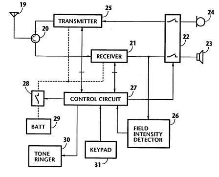
24 In Fig. 4, signal from the nearby access unit is detected by an antenna
25 19 of each cordless station 5k and passed through a duplexer 20 to a
26 receiver 21 where it is converted to an audio-frequency signal and
27 applied through a normally open switching circuit 22 to an earphone 23.
2 8 Signal from microphone 24 is coupled through switching circuit 22 to a
29 transmitter 25 where it is converted to a high-frequency signal and
2040572 74924-10
applied through duplexer 20 to antenna 19. A field intensity
detector 26 is connected to receiver 21 to compare the field
intensity of the cordless station with a prescribed threshold and
applies an output signal to a control circuit 27 if the field
intensity is higher than the threshold. As will be described,
control circuit 27 exchanges control signals with receiver 21 and
transmitter 25 by tuning their frequency synthesizers to the
control channel and switching to a speech channel when it is
assigned by the communicating access unit. For power savings
purposes, a power switch 28 is controlled by control circuit 27 to
cut off power supplies from a battery 29 to receiver 21 and
transmitter 25. A tone ringer 30 is connected to control circuit
27 to audibly alert the user upon receipt of an incoming call from
the network. A keypad 31 is also connected to control circuit 27
to generate an off-hook signal when answering an incoming call or
generate a connection request as well as destination address
information when originating an outgoing call.
Each of the respective control circuits of main
controller 2, access units 4 and cordless stations 5 is a
microprocessor-based controller which is programmed to perform a
stored sequence of instructions as described hereinbelow.
FLOWCHARTS
In Fig. 5, main controller 2 initiates program execution
with sequential steps 41, 42 and 43 which check in succession for
the presence of an incoming call from the network on one of
subscriber lines 61, 62 and 63. If there is one, control proceeds
to step 44 to select two access units one for each service area
2040572
74924-10
and send a first alert signal to both of the selected access units
in order to wait for copied versions of acknowledgment (ACK)
signals from cordless stations which are in a standby state. As
will be described, each selected access unit responds to this
alert signal by broadcasting a recurrent sequence of second alert
signals containing respective identifiers of all standby cordless
stations to notify the arrival of an incoming call, not knowing
which cordless stations are within their own service area.
Therefore, as many ACK signals are returned from each access unit
as there are standby cordless stations within the service area of
the access unit.
Following step 44, a timer is set equal to a period of
t1 seconds (step 4S) and a check is made for the presence of an
acknowledgment signal (ACK) from access units 4 (step 46). If
there is none, control repeats step 46 after checking for the
expiration of timeout period t1 (step 47), and if there is one,
exit is to step 48 to check to see if ACK signals are received
from all standby cordless stations. If the answer is negative,
steps 46 and 48 are repeated until the timeout period t1 expires
(step 49), and if the answer is affirmative, control moves ahead
to step 50 to send a proceed-to-assign signal to the selected
access units, and proceeds to decision step 51 to check to see if
an off-hook signal is returned from one of the selected access
units. If the timeout period t1 expires at step 47, control
returns to step 41 to repeat the process, and if it expires at
step 49, control exits to step 51.
As will be described, the proceed-to-assign signal
`--~ 2040572
74924-10
allows each access unit to assign a common speech channel to the
incoming call and to switch the access unit and cordless stations
to the assigned speech channel so that the cordless stations can
receive ringing signals from the access unit.
If the answer is negative in step 51, this step is
repeated until the incoming call is abandoned from the network
side of the connection (step 52), and if the answer is
affirmative, control advances to step 53 to transmit a speech-
circuit turn-on signal (containing in it the system identifer and
the identifier of the station from which the off-hook signal has
returned) to the access unit which has returned the off-hook
signal,
8a
~i
, ~
NE-335
-9 2040572
operates matrix switch 9 to establish a connection to trip the ringing signal
2 from the network, and transmits a proceed-to-clear signals to the other of
3 the selected access units in order to clear ringing signals supplied from it
4 to cordless stations. Following step 53, main controller 2 enters a talkings mode with respect to the incoming call.
6 In Fig. 6A, if an access unit 4 is in a standby mode, it initiates program
7 execution with step 61 to check for the presence of an alert signal from
8 main controller 2. If the answer is affirmative, exit is to step 62 to set a t2-
9 second timeout period and activate the alert signal generator 1 8 to
1 0 broadcast station alert signals to all cordless stations (step 63) to elicit a
1 1 response from each station. Exit then is to step 64 which checks for the
12 presence of an ACK signal from a cordless station which responded to
13 the alert signal addressed to it. If no ACK is received within the t2-second
1 4 timeout period (steps 64 and 65), control returns to the starting point of
15 the program, recognizing that there is no standby cordless station within
16 the own service area. If the answer in step 64 is affirmative, control goes
17 to step 66 to return an ACK signal to main controller 2 and proceeds to
18 step 67 to check to see if ACK signals are received from all cordless
19 stations of the system. If the answer is negative, control exits to step 68 to
20 repeat a check for the presence of an ACK signal. If there is one, control
21 returns to step 66; otherwise, it advances to step 69 to check to see if a
22 proceed-to-assign signal is received from main controller 2. If the answer
23 iS negative, steps 68 and 69 are repeated until the timeout period t2
2 4 expires (step 70).
2 5 If the decision in step 67, 69 or 70 is affirmative, control advances to26 step 71 to deactivate the alert signal generator 18. Exit then is to step 72
27 to broadcast a channel assignment signal containing the identifier of a
2 8 speech channel to be assigned to the incoming call and the identifier of
29 the cordless station which responded with the earliest of the ACK signals
NE-335
~o 2040572
from cordless stations located in the same service area. Exit then is to
2 steps 73 and 74 to set a t3-second timeout period and switch to the
3 assigned speech channel. Control proceeds to step 75 to check for the
4 reception of an end-of-switching signal from the cordless station identifiedS by the channel assignment signal. If this signal is not received within the
6 t3-second timeout period (steps 75 and 76), control returns to the starting
7 point of the program.
8 If the answer is afffirmative in step 75, exit then is to step 77 (Fig. 6B) to
9 broadcast ringing signals in sequence to those cordless stations which
1 0 returned ACK signals. To avoid undesirable effect caused by a collision
1 1 between simultaneous occurrences of call answering attempts, the ringing
12 signals contain the respective station identifiers of such cordless stations
13 by allowing only one of the stations to return an off-hook signal. Control
14 goes to step 78 to check for the presence of a proceed-to-clear signal
1 s from main controller 2. If this is the case, control exits to step 79 to
16 broadcast a clearing signal to clear the ringing signals. If the answer is
17 negative in step 78, control exits to step 80 to check for the presence of
18 an off-hook signal from a cordless station. Steps 78 and 80 are repeated
1 9 if no off-hook signal is received. If the answer is afffirmative in step 80, exit
2 0 iS to step 81 to return an off-hook signal to main controller 2 to allow it to
21 supply a turn-on signal (step 53, Fig. 5). A t4-second timeout period is
2 2 then set (step 82). Decision step 83 follows to check for the reception of a23 turn-on signal from main controller 2. Step 83 is repeated until t4-second
24 timeout period expires (step 84) and exits the loop to enter a standby
state. If the answer is affirmative in step 83, step 85 is executed by
26 broadcasting a turn-on signal containing in it the identifier of the cordless
27 station which has transmitted the off-hook signal, and control enters a
28 talking mode.
29 In Fig. 7A, if a cordless station is in a standby mode, it begins its
NE-335 2 ~ 5 7 2
program execution with step 90 by turning off power switch 28 to cut off
2 power supplies to transceiver (transmitter 25 and receiver 21) for battery
3 savings purposes. Exit then is to step 91 to set a t5-second timeout
4 period. Steps 92 and 93 are sequentially executed to check for the
5 expiration of the t5-second timeout period and check to see if the
6 cordless station goes off hook. If the station goes off hook or t5-second
7 period expires before the station goes off hook, control moves ahead to
8 step 94 to turn on power switch 28 to activate the transceiver, and
g proceeds to step 9S to switch its frequeny synthesizers to the control
10 channel. A t6-second timeout period is then set (step 96) and the
11 presence of an off-hook condition of the cordless station is again checked
12 (step 97). If the cordless station goes off hook when step 97 is being
13 executed, the user's attempt is a call origination and control moves to a
14 call originating subroutine 100. If no off-hook condition is detected by
15 step 97, a check is made (step 98) for the presence of an output signal
16 from field intensity detector 26 indicating that an incoming call is received.
17 If the answer is negative in step 98, steps 97, 98 are repeated until the t6-
18 second timeout period expires (step 99). If this timeout period expires,
19 control returns to the starting point of the program to repeat the battery
savings process.
21 If the answer is affirmative in step 98, control exits to step 101 (Fig. 7B)
22 to set a t7-second timeout period and goes to step 102 to check for the
23 presence of a station alert signal addressed to the own key telephone
24 system. Since the system has four registered cordless stations, four
25 station alert signals are sequentially received by each cordless station. If
26 no alert signal is received following the generation of an output signal
27 from high intensity detector 26, the t7-second period will expire (step
2 8 103) and the station enters a standby mode. If an alert signal is received,
29 control exits to step 104 to set the t7-second timeout period again and
NE-335 2 0 ~ O ~ 72
proceeds to step 105 to check to see if there is a match between the
2 station identifier contained in the received alert signal and the own station3 identifier. If there is no match, control returns to step 102 to repeat the
4 process. If the answer is affirmative in step 105, control exits to step 106
s to return an ACK signal to the access unit. This ACK signal contains the
6 system identifier and the identifier of the own cordless station. The
7 transmission of this ACK signal will cause the corresponding access unit to
8 deactivate the alert signal generator 26 (step 71, Fig. 6A) and broadcast a
9 channel assignment signal (step 72).
10 Exit then is to step 107 to check for the presence of an channel
11 assignment signal from the access unit. If no channel assignment signal is
12 received, control proceeds to step 108 to check for the presence of a
13 station alert signal. If any of the alert signals of the system is received, the
14 t7-second timeout period is set up again (step 109), with control returning
15 to step 107. If the decisions in steps 107 and 108 are both negative
16 during the timeout period of t7 seconds (step 110), control enters a
17 standby state.
1 8 If the decision in step 107 is affirmative, control exits to step 111 to
19 switch the frequency synthesizers of the cordless station to a speech
channel indicated by the received channel assignment signal. Control
21 then moves to step 112 to check to see if the station identifier contained in
22 the channel assignment signal matches the identifier of the own cordless
2 3 station. If it is, control advances to step 1 13 to check to see if the switched
24 speech channel is in an idle state. If not, control enters a standby mode.
If the switched speech channel is idle, control exits to step 114 to return an
26 end-of switching signal to the access unit, allowing it to proceed to step
27 77 to broadcast ringing signals (Fig. 6B).
2 8 Exit then is to step 115 (Fig. 7C) to set up a tg-second timeout period
29 for successive detection of a ringing signal (step 116) and a turn-on signal
NE-335 2040~
-
(step 117) and a clearing signal (step 1 18) until the timeout period of t8
2 seconds expires (step 120), whereupon control returns to step 95. If the
3 turn-on signal is received (step 117) or if the clearing signal is received
4 (step 118), control proceeds to step 1 19 for deactivating the tone ringer
s and returns to step 95. Steps 117 through 120 are executed by stations
6 which do not go off hook. If the ringing signal is received (step 116),
7 control proceeds to step 121 to check to see if the own station goes off
8 hook. If negative decision is made in step 1 19, control activates tone
9 ringer 30 (step 121 ) to alert the users, and returns to step 115.
10 When the station goes off hook, control exits to step 123 to
1 1 deactivate the tone ringer and proceeds to step 124 to detect a match
12 between the station identifier transmitted by the received ringing signal
13 and the own station identifier. If they fail to match, control returns to step
1 4 1 15, and if a match occurs, control proceeds to step 125 to set the timer
1 s to a timeout period of tg seconds, and proceeds to step 126 to return an
16 off-hook signal containing in it the system identifier and the identifier of
17 the cordless station. Thus, if more than one cordless station goes off
18 hook, the off-hook signal is transmitted only from one of such stations.
19 The transmission of the off-hook signal from the cordless station causes
20 the corresponding access unit to proceed to step 81 (Fig. 6B) to transmit a
21 copy of the received off-hook signal to main controller 2. On receiving
2 2 this copy of off-hook signal, main controller 2 proceeds to step 53 (Fig. 5)23 to return a turn-on signal to the access unit containing in it the system
24 identifier and the identifier of the station going off hook, as well as a
25 proceed-to-clear signal. On receiving this turn-on signal (step 83, Fig. 6B),26 the access unit broadcasts a copy of the received turn-on signal (step 85).
27 Exit then is to step 127 to check for the presence of a turn-on signal
2 8 from the access unit. If this signal is not received within the timeout period
2 9 tg (step 128), control enters a standby mode, and if it is received within
NE-33S
2040572
- 14 -
this period, exits to step 129 to check for a match between the station
2 identifier contained in the turn-on signal and the own identifier. If the
3 answer is affirmative, control exits to step 130 to close the normally open
4 switching circuit 22 and enters a talking mode. If there is a mismatch,
S control returns to step 9S to switch the cordless station to the control
6 channel in order to receive the next incoming call which may
7 immediately follow.
8OPERATION
gThe operation of the system will now be described with reference to
10 the drawings described above together with Fig. 8. Assume that cordless
11 stations 51 and 52 are located in service area 31 and the other cordless
12 stations are located in service area 32 when an incoming call is received
13 on subscriber line 61 from the network and that all cordless stations are in
14 a standby state executing the battery savings steps 90 to 99.
15 The incoming call is detected by line interface 81 of main controller 2,
16and this fact is communicated to control circuit 11 (step 41, Fig. S), which --
17 proceeds to select one access unit for each service area, say, access units
18 41 and 43 for service areas 31 and 32, respectively, and transmits alert
1 9 signals to the selected units (step 44) from local interfaces 1 l and 103 via
20 local lines 71 and 73. More specifically, the alert signal from local
21 interface 10l, for example, is supplied to transmitter 13 of access unit 41
22 and fed into control circuit 17 (step 61, Fig. 6A) and a recurrent sequence
23 of station alert signals 51~ S2, S3 and S4 (Fig. 8) are generated by alert
24 signal generator 18 and broadcast from transmitter 13 by antenna 16 to
25 cordless stations 51 and 52 following the setup of a t2-second timeout
26 period (steps 62 and 63). Station alert signals S1, S2, S3 and 54
27 respectively address to all cordless stations 51~ 52, 53 and 54 of the
2 8 system. Likewise, the same station alert signals are recurrently broadcast
2 9 from access unit 43 to cordless stations 53 and 54.
NE-335
-
-15 2040572
If field intensity detector 26 produces a high-intensity signal (step 98,
2 Fig. 7A), the station alert signals from access unit 41 are detected by the
3 antenna 19 and supplied through receiver 21 of each cordless station to
4 control circuit 27 in which their station identifiers are compared with the
s identifier of the own station to detect a match between them (steps
6 102-105, Fig. 7B). When there is a match (step 105), an
7 acknowledgment (ACK) signal T31 is transmitted (step 106) from
8 transmitter 25 by antenna 19 of station 53 to access unit 43 and ACK
9 signal T41 is transmitted in succession from station 54 to access unit 43. In
10 a similar manner, ACK signal T11 is transmitted from station 51 to access
1 1 unit 41 and ACK signal T21 is transmitted in succession to access unit 41-
12 ACK signals T1 1~ T21, T31 and T41 contain the system identifier and the
13 respective station identifiers as described above.
14 ACK signals T1 1 and T21 are received by the receiver 14 of access
15 unit 41 and supplied to its control circuit 17 in which they are examined to
16 see if they contain the same system identifier as that of the own key
17 telephone system (step 64, Fig. 6A). Likewise, ACK signals T31 and T41
18 are received and examined by access unit 43. In response to ACK signal
19 T1 1~ a copy of this signal is returned from access unit 41 to main controller
20 2 as an ACK signal T12 (step 66) and in response to the next ACK signal
21 T21, a copy of this signal is returned from access unit 41 to main controller22 2 as an ACK signal T22 (steps 67, 68 and 66) to wait for the reception of a
23 proceed-to-assign signal from main controller 2 (step 69). In a similar
24 manner, a copy T32 of ACK signal T31 and a copy T42 of ACK signal T
25 are successively returned from access unit 43 to wait for the proceed-to-
26 assign signal. Note that the order of ACK signals returning from cordless
27 stations may vary depending on the independent timing of their battery
28 savings operations, so that under certain circumstances ACK signal T
29 may arrive first in response to a first sequence of alert signals and T
NE-335
2040572
- 16 -
may arrive last in response to a second sequence of alert signals.
2 On receiving ACK signals from all standby cordless stations (step 48,
3 Fig. 5), main controller 2 sends a proceed-to-assign signal to the selected
4 access units 41 and 43 (step 50).
It is seen that, since the proceed-to-assign signal is generated at the
6 instant when ACK signals corresponding to those from all cordless
7 stations are received by main controller 2, the call terminating process can
8 proceed further to promptly answer the incoming call.
9 In response to the proceed-to-assign signal (step 69, Fig. 6A), access
10 units 41 and 43 turn off their alert signal generator 18 (step 71 ) and
11 broadcast a channel assignment signal (step 72) containing an assigned
12 speech-channel identifier and the identifier of a cordless station which
13 returned the ACK signal of the earliest arrival in each service area, (i.e.,
14 station 51 for access unit 41 and station 53 for access unit 43), switch to the
1 S assigned speech channel (step 74). Access unit 41 now waits for an end-
16 of-switching signal from cordless station 51 (step 75) during timeout
17 period t3 and access unit 43 waits for an end-of-switching signal from
18 cordless station 53.
19 On receiving the channel assignment signal from access unit 41 (step
20 107, Fig. 7B), cordless stations 51 and 52 switch to the assigned speech
2 1 channel (step 111 ) and checks to see if the station identifier contained in
22 the channel assignment signal matches the own station identifiers (step
2 3 1 12). Thus, cordless station 51 exits to step 11 3 to check to see if the
24 assigned channel is idle, and if it is, returns an end-of-switching signal to
2 5 access unit 41 (step 1 14). After setting timeout period tg, cordless stations
2 6 51 and 52 wait for a ringing signal from access unit 41 (steps 115 and 116,
27 Fig. 7C). Likewise, cordless stations 53 and 54 switch to the assigned
28 speech channel in response to the channel assignment signal. Station 53
29 returns an end-of-switchlng signal to access unit 43 (step 114). Stations 53
NE-335 20~0572
and 54 wait for respective ringing signals from access unit 43 after setting
2 timeout period t8-
3 In response to the respective end-of-switching signals from cordless
4 stations 51 and 53 (step 75, Fig. 6A), access units 41 and 43 broadcast
ringing signals each containing the system identifier and the respective
6 station identifier (step 77, Fig. 6B), so that ringing signals V1 and V2 are
7 transmitted to cordless stations 51 and 52, respectively, and ringing signals
8 V3 and V4 are transmitted to cordless stations 53 and 54, respectively.
9 In response to each ringing signal, each cordless station activates ik
tone ringer 30 to alert the user (steps 116, 121 and 122, Fig. 7C). If
1 1 cordless station 51 goes off hook (step 121), it turns off its tone ringer12 (step 123), detects a match between the station identifier contained in the
13 ringing signal and the own station identifier (step 124), and returns an off-
14 hook signal W1 1 to access unit 41 (step 126) to wait for a turn-on signal.
On receiving the off-hook signal W11 (steps 78 and 80, Fig. 6B),
16 access unit 41 returns a copy of the off-hook signal W11 as an off-hook
1 7 signal W12 to main controller 2 (step 81).
18 Main controller 2 responds to the off-hook signal W21 by returning a
19 turn-on signal X1 1 (steps 51 and 53, Fig. 5) to access unit 41 and operating
the switch 9 to establish a connection between line interface 81 and local
21 interface 11, while transmitting a proceed-to-clear signal to access unit22 43.
2 3 In response to the turn-on signal X11 (step 83, Fig. 6B), access unit 4
24 broadcasts a copy X1 2 Of the turn-on signal X1 1 (step 85) to enter a
talking mode. Cordless station 51 responds to this signal (step 127, Fig.
26 7C) by detecting a match between the station identifier contained in it and27 the own identifier (step 129) and turning on the switching circuit 22 to
2 8 activate its speech circuit (step 130). Cordless station 52 responds to turn-
29 on signal X12 when executing step 117 and turns off its tone ringer (step
NE-335
2040572
- 18 -
119) leaving its switching circuit 22 in the off-state, and switches to the
2 control channel (step 95) to receive the next incoming call which may
3 immediately follow.
4 On the other hand, access unit 43 broadcasts a clearing signal in
s response to proceed-to-clear signal (steps 78 and 79, Fig. 6B) and enters
6 a standby state. Cordless stations 53 and 54 receive the clearing signal
7 (step 118) and turns off their tone ringer (step 119) and switch to the
8 control channel (step 95) to receive the next incoming call.
9 It is seen that when the incoming call is answered the standby
0 cordless stations other than the station answering the call- are switched to
the control channel, rather than entering the battery savings routine, the
12 system can quickly respond to the next incoming call which is handled by
13 the access units other than that involved in establishing the previous call.
14 The foregoing description shows only one preferred embodiment of
15 the present invention. Various modifications are apparent to those skilled
6 in the art without departing from the scope of the present invention which
17 is only limited by the appended claims. Therefore, the embodiment
18 shown and described is only illustrative, not restrictive.