Note: Descriptions are shown in the official language in which they were submitted.
-
:
2~ 6~
IP-0815
TITLE
CLOSED AND OPEN TUBE SAMPLING APPARATUS
Field of the Invention
This invention relates to an automatic sampling
apparatus which is capable of automatically sampling the
contents of open as well as closed sample containers.
Back~round of the Invention
In the analytical and diagnostic fields there is a
need to aspirate the contents of plural sample
containers for analysis. While many samples are non-
toxic and non-hazardous and hence may be held in open
containers, it is often desirable to store samples in
tubes which are closed, i.e. they have a cap over their
top. The cap is used from the standpoint of safety to
avoid exposing operators to contact with potentially
hazardous serum and other materials. Often the samples
axe stored in a simple closed container of the type sold
under the tradename Vacutainer~ which finds wide usage
in the blood industry.
As the trend towards automation of the sampling
continues, it is necessary to introduce a probe through
the rubber stopper or cap of the sample container for
~he purpose of aspirating a sample therefrom. In the
past, such automation has been achieved using robotic
systems of the type that provide movement in the X, Y,
and Z directions. Such systems often use stepping
motors as their prime movers. While imminently
satisfactory and precise and accurate, such systems
o~ten encounter difficulties when the container cap is
formed of a heavier, thicker or more resistant material
such as rubber is encountered. This is due to the low
torque provided by most steppin~ motors. Thus while
quite satisfactory for sampling open tubes or open tubes
1 lP-OB15
, . . .
~, . , ,. ~ : .
... .
.
.
:
2 ;2~41~69?~
stoppered with a material which is easily punctured,
stepping motors are not satisfactory for use when use of
ccntainers stoppered with such heavy materials is
necessary.
Typical of the open tube samplers that are
available are those described in U.S. patents 3,719,086,
3,756,959, 3,759,667, 3,912,452, and 4,065,973.
A second problem encountered with the use of
stoppered containers is that they often are evacuated as
in the case of the Vacutainer(~ container due to the
presence of a vacuum within the container. This renders
it more difficult to accurately sample a fixed volume
from the tube due to negative air pressure. Thirdly, it -
is desirable to present stoppered as well as unstoppered
tubes on the same sample carrier.
One sampler which purports to alleviate some of
these difficulties is that described in U.S. patent
4,811,611 issued to Uffenheimer. The Uffenheimer
apparatus is capable of aspirating sample from both
closed and open tubes. A pressure equilibration chamber
prevents vacuum buildup in the closed tube sampler to
ensure the supply of consistent sample quantities
therefrom. Unfortunately the Uffenheimer apparatus
requires that the closed tube be positioned in a
separate portion of the sampler upside down. This
renders automation difficult sirlce open tubes must b~
positioned apart from and differently than the closed
tubes. Also, if automating apparatus is to be used to
position the sample containers and the ~spirating
apparatus must ~e used for the open and closed tubes
respectively. ~dditional Uffenheimer patents of
interest are U.S. 4,799,393 and U.S. 4,756,201.
U.S. patent 4,815,325 (Averatte) discloses a
capillary fluid injector capable of sampling from septum
2 IP-0815
. ~ .
- .
. .
-:
:
3 2~34~9:~
covered vials. Utilizes air cylinders for probe motion
but, each air cylinder is capable of stopping at the end
of travel only. Venting of vial is through co-axial
needle. Does not incorporate level sensing and
aspiration probe always goes to a fixed depth in vial.
U.S. patent 9,311,484 (Fosslien) discloses
automated sampling system for closed tubes only in which
the tube to be sampled is held horizontally. Venting is
accomplished by venting the prohe to atmosphere. Due to
the horizontal tube position venting will create bubbles
in the sample which can affect aspiration. No level
sensing is incorporated and the probe always enters to a
fixed depth. Actuation of the probe into the tube is by
motorized cam drive.
U.S. patent 3,~72,730 (Ringrose et al.) discloses
sampling system for closed tubes only in which the tube
to be sampled is held horizontally and must be manually
inserted. Venting is accomplished by a second probe
which is open to atmosphere. Due to the horizontal tube
position venting will create bubbles in the sample which
can affect aspiration. No level sensing is incorporated
and the probe always enters to a fixed depth. Actuation
of the probe into the tube is manual.
AU-A-16756/88 (Mawhirt et al.) discloses an
automated sampling system for closed tubes only in which
the tube to be sampled is inverted. Venting is
accomplished by venting the probe to atmosphere. Due to
the vertical tube position ventin~ will create bubbles
in the sample which can af~ect aspiration. No level
sensing is incorporated and the probe always enters to a
fixed depth. Actuation of the probe into the tube is by
air cylinder.
3 IP-081S
: . . : : . .~
'
. . ~ '
;, , . ~ .- ~ . . .~ . . .
S~mmary of the Invention
The apparatus of this invention overcomes many of
the problems encountered in prior art automatic samplers
an~ permitting open tube as well as closed tube sampling
particularly when the tubes are positioned on the same
rotary tray or carousel. Pressure within the closed
tube is compensated. Adequate force is provided to
permit the sampling probe to penetrate the cap of the
closed tube. ~he subject apparatus of this invention
has a sample carrier adapted to move a plurality of
sample containers in a sampling position, a lateral
translator located to have a path o~ movement over the
sampling positions, a vertical translator mounted to be
positioned by the horizontal translator, a sampling
probe adapted to be positioned vertically by the
vertical translator into and out of the sample
containers, a liquid pump connected to the probe to
aspirate sample from the sample containers, and
controller means to actuate the translators and pump to
effect such aspirators. The apparatus of this invention
improves the sampling apparatus by the use of pneumatic
translators, upri~ht sample containers wherein at least
one sample container is closed. This sampling apparatus
includes a retaining bracket for the sample containers
positioned to limit their upward movement during probe
withdrawal from the container.
A trans~er vessel is located along the path of
movement of the lateral translator and the controller
means operates the lateral translator to position the
probe over the transfer vessel, the vertical translator
and pump operating to discharge aspirated sample into
the transfer vessel. A wash receptacle may be located
along the path of the movement of the lateral
transla~or, the controller means operating the lateral
~ IP-~815
: ~ .. - - .
- . ~ : ': .
;~04069."
translator to position the probe over the wash
receptacle. The apparatus also includes a source of
wash liquid, the pump being coupled to the source, and
includes a vertical translator and pump operating to
5 discharge wash liquid into the receptacle and to dip the
probe into the receptacle to wash the probe.
The apparatus also is constructed so that the pump
is connected by a conduit to ~he probe and includes a
valve positioned in the conduit and responsive to the
controller veins to opening the conduit to atmospheric
pressure immediately prior to sample laseration, to
equilibrate the pressure in closed sample containers.
Thus constructed the automaLic sampler provides
more convenient and flexible sample loading onto a
sample wheel without reconfiguring the hardware,
software or switch selective valves to accommodate
either open or closed sample tubes. Both types of
containers, open as well as closed, by not requiring
removal of the caps from the sample containers,
laboratory productivity and particularly laboratory
safety due to the removal of the hazardous material
problem is substantially reduced.
Description of thel~wi~s
The invention may be better understood by the
following detailed description when taken together with
the accompanying drawings in which:
Figure 1 is a diagrammatic view of an automatic
sampling apparatus constructed in accordance with this
invention:
Figure 2 is a plan view of the closed container
sampling apparatus shown in Fig. 1: and
Figure 3 is a block diagram of electronics used to
control the apparatus of Fig. 1.
IP-0815
., , . , , j .
: . . . ~ ,~
,:
6 2~6~ -
Detailed Description of the Preferred Embodiment
The sampling apparatus which is capable of sampling
either open or closed sample containers with equally
facility is best seen with reference to Figs. 1 and 2.
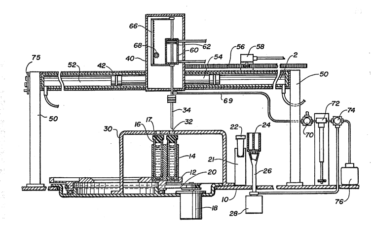
In Figure 1 the sampler has a base member 10. A sample
carousel or wheel 12 is mounted on the base member. The
sample wheel 12 typically rotates in one direction only
and has a plurality of carriers 19 adapted to hold
plural sample containers 16 of either the open and/or
closed end variety. The sample containers of the closed
end variety may typically be those which are sold for
the purpose of collecting blood samples under the
trademarks of ~acutainer~, Venor Jet, or others. The
sample wheel 1~ is driven by a motor 18 through a pulley
20 all of conventional design.
Also mounted on the base 10 is a pedestal 21
adapted to hold a transfer vessel 22. A probe wash
station 24 is positioned adjacent to the transfer vessel
22 and the two are in general alignment along a straight
line intersecting the sampling location for the sample
container 16. The wash station 29 has a drain pipe 26
which ends in a waste container 28. A retainer 30 is
positioned over the sample wheel 12 and is positioned so
as to prevent the upward movement of a sample container
16 once they are positioned under the retainer 30. The
retainer 30 as may be best seen in Fig. 2 may be arcuate
in shape. Holes 32 are formed the retainer 30 above the
sampling location of the sample containers so as to
admit the entry therethrough of a needle probe 34 which,
as will be described, is used to extract sample and
penetrate the stopper 17, if there ~e one.
The probe 34 is mounted on X and Z (horizontal and
vertical) translators 40 and 42, respectively. These
translators operate to position the probe 34
6 IP-0815
,
.
6~3
horizontally first above the sample containers 16 then
over the transfer vessel 22 and finally over the wash
station 29. The XZ translator operates to move the
probe 34 vertically into and out of the sample container
5 16, the transfer vessel 22, if desired, and finally the
wash station 29.
The horizontal translator 42 is mounted on
stanchions 50 which in turn are mounted on the base 10
and mounts the Z-axis translation 40. The translator 92
10 includes a bang-bang fluid rnotor 52 has a piston 54 that
slides back and forth therein as will be described. The
fluid motor may be pneumatic or hydraulic, the former
being preferred.
The piston 54 is in turn connected to position a
lS Z-axis translator qO and also drives a pinion rack 56
which in turn drives an X-axis encoder 58.
The Z-axis translator is also a bang-bang fluid
motor 60, and includes a piston 62. A Z-axis pinion
drive rack 66 is attached to the shaft driven by the
20 piston 62 and engages a rotary encoder 68. The piston
62 is connected to drive the probe 34 in a vertical
direction. The probe is connected to receive fluid
through a tube 69 which is connected through a 2-way
valve 70 to a pump 72. The pump 72 in turn is connected
25 through a second 2-way valve 74 to a supply of wash
buffer 76. The second outlet of the first valve 70 is
connected to a vent to atmosphere. The pressure lines
for the X and Z axis translators 42 and 40 are connected
to suitable servo valves which are seen most clearly in
30 Fig. 3. Before going to Fig. 3, it should be stated
that the structure of the automatic sampling apparacus
is controlled by a controller 80 which is shown
schematically and will be described with particular
reference to Fig. 3. The control system of Fig. 3 in
7 IP--0815
:
, . : :
.:
, ~ . .
8 2~0~
addition to operating the translators 40 and 42 receives
information from the encoders 58 and 68 and controls the
operation of the respective servo valves 90 (Fig. 3)
pumps and the liquid valves 70 and 79. The liquid
valves 70 and 74 may be conventional solenoid operated
valves. A level sensor 75, of conventional design,
associated with the probe, for sensing the liquid level
in the sample containers is coupled to the controller 80
to control the depth to which the probe is moved.
There may be seen in Fig. 3 a block diagram of the
control system for the automatic sampler. The
controller 80 may be any program controllable chip which
stores information as to sample quantity, and is
responsive to the probe level sense circuit 75 to
provide input to the digital positioning board 92 one of
the translators 40 or 42. For the sake of simplicity,
the only translator described is the horizontal
translator 42 although both function the same way. The
horizontal encoder is seen as represented by the circle
58 and the bang-bang fluid motor or actuator by the
block 52. The servo valve 90 controls the operation of
air from a sui~able air supply ~not shown) to either end
of the actuator 52. The control system may be seen as
including the encoder 58, the actuator 52, the servo
valve 90, the controller 80 and a digital positioning
board 92 and converts a bang-ban~ pneamatic actuator to
an actuator that is capable of precise position control.
The positioning encoder 58 which might be any suitable
rotary encoder such as a Lucas Ledex K3-DM-2500-5SE-4~ -
pro~ides outputs that are in quadrature. By sampling
these outputs, the digital positionin~ board 92 is able
to determina the direction of the actuator as well as
the number of positions moved.
8 IP-0815
- : ,
:. ' , - . ;' ,
`:
.
:
-- 2~
9 , -,
The servo valve 90 which may be any suitable servo
valve, however, one manufactured by Atchley Controls,
model 204PN is preferred. Such servo valve is a two
stage jet-pipe servo valve. The first stage uses a
tor~ue driven jet-pipe which directs the airflow into
one of two receiver orifices. Each orifice is connected
to one end of a second stage spool which is directly
connected to the output ports. When an actuator
position is achieved,~the valve is at null and the dual
output ports reach an equal pressure balance.
The digital positioning board may, for example, be
an Automation Plus, model DPC-256. ~he digital
positioning board consists of a data latch, an edge
detect circuit, a counter chain, digital subtractor,
digital-to-analo~ converter and a servo amplifier. Two
8-bit tri-state latches let position programming and
readback to occur on the same bus. A 4X edge detect
circuit is used to react to every possible quadrature
state, thereby eliminating positioning errors due to
encoder shaft vibrations. A 1~ bit up/down counter
chain accepts counts from the edge detect circuit. The
12 bits from the counter chain are sent to a digital
subtraction circuit. The 4 least significant bits are
used for correction of any drift in the actuators
position. The carry out on the digital subtraction
circuit is used as a direction pointer. The 8 most
significant bits are used in digital subtraction and
drive the 10 ~it digital-to-analog ~D/A) converter. The
10 bit D/A converter works in conjunction with summing
amplifiers and a servo amplifier. Corrections in
position drift due to the expansion and contraction o~
air lines, com~ressibility of air, or offsets in the
servo valve are automatically made by ~sing the least
significant bit of the D/A converter. The controller 80
9 IP-0815
. :. : -~: :: , :
2~ 9~
provides position data and preferably is TTL compatible.
When 8 bit parallel data is sent to the input data latch
on the digital positioning board and a write pulse is
generated, the actuator will move to a position
proportional to the data at the input latch. For
example, i~ the actuator has 6 inches of linear travel
when at position 255, sending 128 decimal to the input
data latch will move the actuator 3 inches back from its
previous position of 255. Sending a read pulse to the
output data latch will allow the data source to input
position data and verify that the desired actuator
position was achieved. Tight software control is not
required to control and maintain the actuators movement.
Once data and a write pulse are sent to the digital
positionin~ board, the controller is free to perform
other functions. The actuator 52 may be Bimba*02-3-
DXDE, Bimba Pneu-Tur~ PT-017-078 Tolomatic*BC-100-P-6.5.
When air is applied to an input of an air cylinder, the
actuator will move either in or out depending on what
input the air was applied. Typically, a rack and pinion
is mounted to the cylinder and the actuator. A rotary
encoder is then mounted to the pinion gear. As the
actuator 52 moves, the encoder rotates. This causes the
encoder to generate pulses that are sent to the digital
positioning board 92 as described.
Q~a~L~
The operation of the automatic sampling apparatus
may be best understood by reference to Figs. 1 and 2 in
which sample, e.g. blood, collection tubes 16 with or
without caps 17 ~re placed in carriers 14 and staged on
the sample wheel 12. The sample wheel rotate~ in one
direction only, to present each blood collection tube in
sequence beneath the tube retainer 30 and probe 3~.
When the blood collection tube lS is in the correct
* trade mark.
IP-0815
. ~ .
position, the controller commands sample wheel 12 motor
18 to stop beneath the sampling position. An electronic
signal is sent to the X-axis rotary encoder by the
positioning board 92 to sense for the relevant lateral
position directly over the tube. Instantaneously a
command signal is sent to the X-axis servo valve 90 from
the positioning board to supply air to the correct port
of the X-axis fluid motor to drive the probe 3~ in a
lateral direction toward the blood collection tubes. As
the needle probe is moved by air toward the blood
collection tube, the electronic rotary encoder, geared
to the pinion driving rack 56 is forced to count by its
rotating motion as it moves down th~ linear rack. When
the rotary encoder has reached the correct position over
the appropriate blood collection tube, it sends a signal
to the servo valve via the positioning board to equalize
air pressure in both ports (Pl & P2) of the X-axis fluid
motor 42 thus stopping and locking its position directly
over the appropriate blood collection tube 1~. When the
X-axis fluid motor has been locked into position by
equalized air pressure, a command signal is sent to the
second servo valve via the controller to supply fluid to
the correct port of the Z-axis fluid motor to move the
needle probe down through the (rubber) cap into the
blood collection tube.
As the tip of the needle probe penetrates the
rubber cap o~ the tube and exits the other side, and
before entering the serum, a command signal is sent to -~-
the pump 72 to with~raw all fluid in the needle probe
conduit back through the pump valve 70. ~he valve 70 is
switched by the controller 80 to place conduit 6~ in
communication with atmosph~ric pressure to permit vacuum
inside the tube above the serum level to equil~brate.
All of this is accomplished almost instantaneously when
11 IP-0815
.. :: .: .: -
:.- ~ ~ ,, . :.
i . , , , .: ~
12
the probe 34 enters the closed tube. Then the
controller switches the valve back to the pump 72 and
aspirates sample. To those skilled in the art, the
relief of vacuum entrapped in a closed container above
the fluid line is necessary to assure a precise
aspiration of a desired sample quantity.
Before the needle probe enters the serum sample,
the controller polls the level sense logic device 75 for
the level of the serum sample. The level sense lo~ic
device sends a signal back to the controller 80 that the
sample level has not been detected. Then the controller
sends a signal to the servo valve 90 to supply fluid
pressure to the Z-axis fluid motor to move the probe 34
down into the tube further. As the needle probe 34
moves further down into the tube, the level sense logic
device is trying to detect a change in frequency. When
the needle probe touches the fluid, a change in
frequency is detected by ~he level sense logic device.
It sends a signal back to the controller 80 that it has
sensed sample and the controller signals the servo
through the positioning board ~2 to foxce the Z-axis
fluid motor down an additional distance equivalent to 10
steps as deter~ined by the electxonic rotary encoder.
This immerses the needle probe hole deep enough into the
~5 sample to permit evacuation of sample through the hole
into the pro~e.
When sample has been aspirated, the controller 80
signals the servo 90 to supply fluid to the Z-axis port
to move the probe up. Instantaneously a si~nal is sent
by the controller to the Z-axis rotary encoder to count
position as the needle probe is raised. When the needle
reaches the appropriate position, the rotary encoder
sends a command to the servo valve via the controller
and positioning board to supply fl~id to both ports of
12 IP-0815
:, ~ , . . .............................. .
... .
, : . ,
13 20~6~3
Z-axis fluid motor, thus locking the probe in the
appropriate position. Upon locking the Z-axis fluid
motor in the appropriate position the controller signals
the servo valve to supply fluid to ~he correct X-axis
fluid motor port to laterally move the needle probe
The controller signals the electronic encoder to count
positions as the probe is moved to transfer the
aspirated sample to a ~ransfer vessel. Upon reaching
the desired lateral position, the encoder 58 signals the
servo valve 90 via the controller 80 to supply fluid to
X-axis fluid motor ports stopping the needle probe over
the transfer vessel. Then the controller 80 signals the
Z-axis fluid motor port to move the probe down a
designated number of steps as determined by the Z-axis
rotary encoder. As the probe moves down, the rotary
encoder counts the probe's relative position and signals
the servo valve 90 via the controller 80 when the probe
has reached the appropriate position. At the
appropriate position or number of counts, the rotary
encoder signals the servo valve 90 via the controller to
supply fluid to both fluid motor ports to stop the probe
34. The controller 80 signals the pump to dispense the
sample into the transfer vessel. After dispensing of
the sample int~ the transfer vessel 22, the controller
80 signals the servo valve 90 and rotary encoder and
moves the probe to a wash station 24 for needle probe
tip cleaning.
As the probe is moved into the wash station 24 by
the controller, the needle pro~e 34 is driven down into
the drain at the appropriate position as designated by
the controller and determined by the Z-axis rotary
encoder. The controller signals the valve 70, 7~ to
switch to communicate the pump 72 with conduit 68 and
the controller signals the pump 72 to flush the needle
13 IP-0815
,: , , ,. :
' ~ . ' ' ' , ' . ,
14 ~ 6~
probe via valve 74 with dlstilled water from wash 76.
As the distilled water exits the probe 34, water i9
forced up around the outside of the probe tip as
facilitated by the wash station geometry and then flows
out of the wash station down into the liquid waste
container 28. The controller 80 then raises the probe
3q in accordance with the previous teachings and is
ready to move to another sample tube.
Although the closed tube sample method of this
invention has been heretofore representatively
illustrated, the same method is used for open tube
sampling without piercing a rubber cap. Because
piercing the rubber requires the greater force and
optimized geometry and design of the needle probe, it is
clear for those skilled in the art that open tube
sampling is achieved using the same method and hardware
with relative and less challenging ease.
In an alternative embodiment invention instead of a
horizontal translator, a rotary translator may be used
instead. In this case, as before, a Z-axis translator
is mounted on a rotary translator operating in the
horizontal plane. The advantage of a rotary translator
is that in some situations it will result in space
saving. Either one may be used with equal facility.
l~ IP-0815