Note: Descriptions are shown in the official language in which they were submitted.
204~71~
1 56,016
FACSIMILE MACHINE USING THIN FILM
ELECTROLUMINESCENT DEVICE
BACKGROUND OF THE INVENTION
The invention relates to a facsimile machine of
the type having two modes of operation. In the read mode
a document is scanned and the image of the document is
s converted into an electrical signal which is
representative of the image. This electrical signal can
- then be-stored, transmitted via telephone or radio wave,
or processed in another manner. In the second or write
mode the facsimile machine receives an electrical signal,
such as for instance from a telephone line, and converts
the electrical signal into a fixed copy of the image
represented by such electrical signal. Such facsimile,
or fax, machines typically output the copy on a medium
such as paper. It is highly desirable that one machine
perform both functions by operating in both read and
write modes. Typically prior art designs used separate
2~071~
2 56,016
mechanisms for the read mode in which a light source is
directed upon the document and a signal is produced by
the reflected light from the document as it is detected
by a photQelectric detector which typically would be a
photoelectric cell or similar sensor. Separate apparatus
wi~hin the machine is used when an image signal is
received by the fax machine to convert that image signal
into an actual fixed copy. Prior art devices have
included thermal paper, and photographic means. More
recently fax machines have used a scanning laser head to
place a photo image on a photo receptor device such as an
electro-static drum copier. Such laser heads are
relatively large and expensive, and in many instances
require complicated scanning mirrors. Both thermal
printing heads and scanned laser printing heads are
relatively slow and often require that the signal to be
.
processed must be stored as it is received from a
transmission line. Prior art fax machines have basically
housed two separate systems, one being a copier, and one
being a reading scanner device with ~ittle integration of
the two separate functions.
Thin film electroluminescent line array emitters
and printers using such are known. An example of this
type of application is disclosed in U.S. Patent 4,535,341
to Kun et al., one of the inventors of the present
invention, and this patent being assigned to the assignee
~0715
3 56,016
of the present invention. U.S. Patent 4,535,341 is
incorporated herein by reference. Other examples of thin
film electroluminescent devices being used in printers
are shown in U.S. Patents 4,734,723 and 4,807,047.
It is an object of this invention to provide a
facsimile machine which uses a thin film
electroluminescent device to provide the photo-imaging
source to a photoreceptor in the write mode, and also to
provide the source for illuminating the paper when a
scanning sensor is used in the reading mode.
It is also an object of this invention to
provide a second source of light from a thin film
electroluminescent device to be used during the read mode
of a facsimile machine.
SUMM~RY OF THE INVENTION
A thin film electroluminescent line array
structure having edge emitting pixels is positioned in a
facsimile machine so as to selectively direct at least a
portion of the light emitted from said pixels to a
photoreceptor copying means when the facsimile machine is
in the write mode. Light from the same pixels is also
used to illuminate the document providing an image to a
scanning sensor element when the facsimile machine is in
the read mode. The single light source provides the
lighting function for both read and write modes. The
20~071~
4 56,016
photosensor element for the read mode can be attached to
the substrate of the pixel array or can be part of the
same substrate as the pixel array. While the primary
light out of the edge of the pixels is directed to
produce a high resolution image on the photoreceptor
copying equipment in the read mode; secondary light
emissions from the edges intermediate adjacent pixels can
be used as a source of illumination for the read mode.
The electroluminescent thin film array can be positioned
in a manner so as to be adjacent the scanner sensor and
the document in a read mode and moved to a position
adjacent the photoreceptor copier in the write mode.
Alternative document and paper paths may be used for the
read and write mode, respectively, permitting the pixel
array to remain fixed.
BRIEF DESCRIPTION OF THE DRAWINGS
The features and advantages of the invention
will become apparent from consideration of the
description in connection with the accompanying figures
in which:
Figure 1 is a diagrammatic illustration shown in
partial cross section of a thin film electroluminescent
line array showing four adjacent pixels.
2Q~0~15
56,016
Figure 2 is a diagrammatic illustration of a
presently preferred embodiment using a pixel array which
is shown in a write mode position.
Figure 3 is a diagrammatic illustration of the
embodiment shown in Figure 2 with the pixel array moved
to a read mode position.
Figure 4 is a block diagram showing a control
scheme for operation of a thin film electroluminescent
array light source in a dual mode facsimile machine.
Figure 5 is a diagrammatic representation of a
thin film device having electro-optical pixel array and
photosensors on a common substrate.
Figure 6 is a diagrammatic illustration showing
a pair of substrates, one containing an
electroluminescent pixel array, and the other having
respective photosensors.
Figure 7 is a diagrammatic illustration of a
presently preferred embodiment showing a single head
having both a light emitting pixel array and
photosensitive sensor arrangements, shown in the write
mode.
Figure 8 is a diagrammatic representation of an
embodiment similar to that shown in Figure 7 in a read
mode.
204071~
6 56,016
Figure 9 is fragmented view in partial section
of a diagrammatic representation of a pixel array similar
to that shown in Figure 1, having primary and secondary
light emissions.
Figure 10 is a diagrammatic illustration of a
presently preferred embodiment having a fixed thin film
electroluminescent pixel array.
DESCRIPTION OF FIGURES AND EMBODIMENTS
The invention is directed to the use of a thin
film electroluminescent device which acts as a high
resolution electronic controlled light source for photo-
imaging and as a light source for a scanning sensor in a
facsimile machine.
Thin film electroluminescent devices are well
suited to use in forming a line array of pixels, each
emitting a controlled beam of light at the edge of the
device. The edge emitted light is of high intensity and
provides very good resolution in imaging systems. A
typical array for use in a facsimile machine is shown in
Figure 1. The array 1 shown has four pixels, 2a, b, c,
d. It is to be understood that in an actual facsimile
machine using the invention the pixel array device would
be composed of hundreds or thousands of similarly
arranged pixels. The pixels are formed on a substrate
material 3 having a common electrode 4 which is
2 0 ~
7 56,016
electrically connected to an excitation source 5. The
upper surface of each respective pixel contains a pixel
electrode which is connected to a controlling electrical
signal through a signal switching device such as
represented at 6a, b, c, d. When a signal is provided to
the pixel electrode by means of switch device 6a through
d, a respective primary light beam Pa, Pb, Pc, Pd is
caused to emit from the edge of the respective pixel.
Switches 6a through d are diagrammatic in nature and in
the actual facsimile machine electronic switching
circuitry would be used to generate respective pixel
signals.
Figure 2 shows a diagrammatic representation of
a facsimile machine embodying the invention. As shown
the machine would be in a write mode. A paper path 8
exists which would deliver plain paper to the
electrostatic copy portion of the machine and remove the
fixed paper copy from the machine. A scanning sensor 7
is shown, but would not be in operation in the write
mode. Control 13 provides signals representative of an
image via cable 14 to a pixel head 11. The pixel head 11
is similar to that shown in Figure 1 and comprises a line
array of edge emitting light devices or pixels. The
light beams from the pixel head 11 are focused through a
lens 12 to a photoreceptive device, such as drum 9. The
drum 9 is an electrostatic charge type device, the
2 0 ~ 0 7 1 ~
8 56,016
operation of which is well-known. A toner developer 10
is used in conjunction with the drum 9 to provide a
transfer of the image from the drum to the paper on paper
path 8. Other well-known elements in the photostatic
copying process between the drum 9 and the paper on paper
path 8 have been omitted for simplicity.
Figure 3 shows the apparatus of the facsimile
machine as depicted in Figure 2 in the read mode. In the
read mode it is desired to convert the image on an
original document into electrical signals representative
of that image for transmission, storage, or for later
generation into a copy. In Figure 3 the drum 9 and write
mode focusing lens 12 are shown but are not operating.
The pixel head 11 has been directed toward a document
path 16. Control 13 now supplies via cable 14 signals to
provide a source of illuminating light from the pixel
head 11 to reflect upon an original document moving on
the document path 16 and thereby provide a signal to the
scanning sensor 7. The scanning sensor 7 is a
photosensitive device, such as a photocell, which
generates a signal representative of the image contained
on the document. Scanning sensor 7 could be either
resistive or a semiconductor device which provides an
output signal to cable 15 which is representative of the
image contained on the document. Control 13 can process
the signal from the scanning head 7 when the facsimile
2~07~
9 56,016
machine is in the read mode, and a typical control
process would be to transmit the signal to a telephone or
radio transmission output.
As can be seen from Figures 2 and 3, the same
pixel head is used for the dual functions of illuminating
the document in the read mode and forming the image in
the write mode. In this particular embodiment the pixel
array head 11 has been displaced to cause the emitted
beam to illuminate either the photoreceptor or the
original document. In other embodiments it will be
understood that the array will be relatively fixed while
lenses or other means can be used to direct the emitted
beam to its two functions.
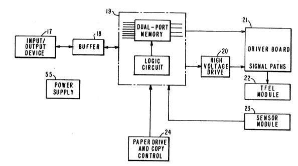
Figure 4 shows a portion of a control having an
input/output device 17 which could include devices such
as personal computer, telephone transmission interfaces,
or other known devices. Signals from 17 can be stored in
buffer 18 when the speed of reception or transmission
exceeds that of the read or write modes of the fax
machines. One of the advantages of the present preferred
embodiment using the pixel array is that such fax
machines can process or generate signals in the read and
write modes at a rate equal to or greater than that of
the telephone transmission line. Therefore, buffer
storage, such as 18, can usually be omitted. Control
circuit 19 controls both the sensor module 23 and the
7 ~ ~
56,016
thin film electroluminescent (TFEL) module 22. High
voltage drive 20 is used as an excitation source for the
pixel array. Driver board 21 provides an interface for
the signal path to the TFEL module 22. A general power
supply source 25 is available for all control devices.
In addition to the TFEL module 22 and the sensor module
23 other functions of the fax machine to control the
copying and paper drive are provided for by the auxiliary
control circuit 24.
The control scheme shown in Figure 4 can be used
to selectively activate pixels in the array 1, such that
in the read mode some portions of the documents are
illuminated and others are not illuminated. This can be
used for many purposes, including security of
transmission, and to shorten signals by deleting unwanted
areas of scan during the read mode.
One of the advantages o the TFEL pixel
arrangement using edge emitting light beams is the small
size of the head used in the control lighting during the
write mode. Further optimization of the facsimile
machine function can be obtained by integrating the pixel
array with the scanning sensor.
Figure 5 shows a diagrammatic representation of
an integrated structure 25 having a substrate 26 which
has an area 27 containing a TFEL pixel array. On the
opposite side of the substrate from the pixel array 27 is
2 ~
11 56,016
arranged a scanning sensor array 28. As diagrammatically
shown in Figure 5, it is to be understood that areas 27
and 28 contain many discrete light emLtting pixels in 27
and many discrete photosensitive areas in the scanning
5 sensor area 28. One of the advantages of the structure
shown at 25 is that the distance between respective
pixels and sensor elements 27, 28 can be on the order of
a few millimeters or less. Such narrow distance between
the light source and its respective scanning sensor in
the read mode can provide high resolution signals.
Figure 6 shows a composite TF~L head 29 having a
substrate 30 bonded to a second substrate 31. The bonded
area at 32 can be controlled in its dimension between
respective substrates. A pixel array area 33 is formed
on substrate 30 along the lower edge portion adjacent
substrate 31. Formed on the upper surface of substrate
31 is a scanning sensor area 34 which is adjacent the
pixel array 33. In this embodiment by controlling the
distance between the substrates 30, 31 in the area of
bonding 32 an optimum distance and angle between the
light source and scanning sensor can be maintained in the
read mode of the fax machine.
operation of a head having a TFEL pixel array
and scanning sensors is shown in Figures 7 and 8. Figure
7 shows a write mode of a facsimile machine having a
photoreceptor such as drum 9 with associated toner roller
7 ~ ~
12 56,016
10 and other known electrostatic copying equipment not
being shown. Paper path 8 removes the image from the
photoreceptor drum 9. The head 35 has a pixel array
portion 36 attached thereto a scanning sensor arrangement
37. Head 35 could be composed of either separate pixel
array and scanning sensors or could use the structures
shown in Figures 5 and 6. In the write mode controlled
light emissions from the pixel array of TFEL devices 36
provide an image to the drum. In the write mode the
sensor arrangement 37 is not utilized. In Figure 8 a fax
machine similar to that shown in Figure 7 is seen where a
document path 16 is established intermediate the head 35
and the photoreceptor drum 9. Establishing the document
path this way permits the head to remain relatively fixed
in the same position. Head 35 having pixel array portion
36 and scanning sensor portion 37 is shown in the read
mode of the fax machine. Illuminating light from the
TFEL portion 36 are directed to the original document and
reflected to the scanning sensor portion 37, thereby
providing an output signal from the scanning sensor 37
representative of the image contained on the document.
While the combined pixel and scanning sensor head 35
shown in Figures 7 and 8 have been shown as a generally
fixed head device such head can also be utilized in a
movable position as shown in Figures 2 and 3. In
addition while the Figures 7 and 8 do not show optic or
2~71~
13 56,016
lens systems on either the pixel array 36 or the sensory
head 37, optical systems such as lenses can be used to
fuxther enhance the performance of the device or to
direct the output beam.
The pixel arrangement as shown in Figure 1 shows
primary light emissions generating a generally
rectangular cross-sectional area beam of light being
emitted from the face edge of the pixels 2a through 2d.
In addition to this face edge emission of primary light,
stray or secondary light is also emitted from the pixels.
Figure 9 is a fragmented diagrammatic illustration of a
pixel array as used in a facsimile machine having pixels
39 and 40 formed on substrate 38. It is to be understood
that actual arrays would contain many more pixels. The
pixel 40 is excited via common electrode 42. When the
signal switch 41 is operated a primary controlled light
beam P is emitted from the face edge of the pixel 40.
Also emitted during excitation of the pixel is a
secondary or stray light emission represented by S1
through S5. While the secondary emission has been shown
as series of discrete beams it is to be understood that a
generally continuous beam of emission of light occurs all
along the side edges of each pixel. S1, S2 and S3 show
emission from the inner side edge of the pixel while S4
and S5 are representative of emissions out of the closer
side edge of the pixel. While in some applications of
2 ~
14 56,016
the device this secondary emission will not be utilized
in the operation of the pixel array, one presently
preferred embodiment does utilize the secondary emission
from the pixel. Because the pixel by its structure tends
to be longer on its side, approximately 40 millimeters,
than on its face edge, approximately 1 millimeter, the
area for light emission is greater on the side edges of
the pixel 40 in the area of the secondary emissions S
through S5 than in the primary emissi~n P. In prior
discussed embodiments i~ was shown how a TFEL pixel array
can be used in both the write and read mode. The
principal, P, beam is used from the pixel to accomplish
both of these operations. Another preferred embodiment
is to use the secondary emission S from the pixels as the
illuminating source during the read mode. The secondary
emission can be used separately as a light source in the
read mode or combined with the primary beam emitted from
the pixel to be used as the illuminating light source in
the read mode. It may be desirable to use an optical
system in connection with the secondary emission to focus
or collect the secondary emission to better direct it to
the original document. Lens systems may be attached to
the head or the substrate in the area of the secondary
emission to direct the secondary emission in the read
mode.
2 ~
56,016
Figure 10 shows a diagrammatic representation of
a fax machine using both the primary and secondary
emissions from a pixel array. Photoreceptor drum 9 and
toner 10 are as previously described. A document/paper
path 45 delivers both paper to the photoelectrostatic
copying portion of the facsimile machine and documents to
the scanner in the read mode. As can be understood,
separate document and paper paths may be used in this
embodiment. A TFEL pixel array head 45 uses both primary
lo and secondary light emissions as shown in Figure 9.
Primary emissions 47 from the head 45 are directed
through a lens 46 and onto a photoreceptive drum 9 during
the write mode. Durins the read mode the secondary
emission from the pixel array head 45 are directed
through lens 48 to create an illumination beam from
secondary emission 49 which is directed to a document on
. _ .
the document path 44, and then to reflect to the scanning
sensor 50. By using contr~ls as previously described the
single TFEL pixel array head 45 can be controlled to
provide a primary emission beam 47 to image on
photoreceptor drum 9 during the write mode and a
secondary emission beam 49 to provide illuminating light
during the read mode to the scanning sensor 50.
2~71~
16 56,016
Based on the foregoing description of the
invention other different embodiments of the present
invention may be constructed without departing from the
spirit and.scope of the present invention.