Note: Descriptions are shown in the official language in which they were submitted.
~~~~~a~~
IdtODZILAR cONVEYOR
73ACEGROUND OF THE INVENTION
Field of the Invention
This invention relates to a modular conveyor wh:Lch
is capable of being adapted to different sizes and shapes by
joining modular assemblies of the conveyor end to end.
Description of the Related Art
U.S. Patent No. 3,456,776, issued July 22, 1969 to
0 Viene, discloses a conventional sanitary food conveyor. The
conveyor comprises a number of straight frame sections
joined together. The framework is mounted upon ieg supports
which are mounted to wheels.
U.S. Patent No. 2,632,556, issued March 24, 7.953
~-5 to Alpers et al., discloses a conveyor having connecting
troughs to connect a main trough to hopper and discharge
troughs at various angular configurations with respect to
each other. An interconnecting link connects the troughs at
various angular positions through pivot pins. The troughs
20 are formed of conventional side slats.
A more convenient way of providing a change in the
height of a conveyor belt is needed. Also, a conveyor like
that disclosed in Alpers et al. c:an only assume a limited
number of sizes and shapes because of its rigid
25 construction. Thus, there is a need for a conveyor which
may be adapted to various sizes and shapes. Secondly, a
conveyor is needed that can be adapted to convey materials
at a different height but without having to adjust the
length of the conveyor belt. Furthermore, it would be
30 desirable to injection mold or die cast each of the parts of
such a conveyor.
SUMMARY OF THE INVENTION
According to the invention, a conveyor has a belt
support frame, leg supports for the belt support frame and a
_1_
continuous belt supported and guided by the belt support
frame for continuous movement. The invention provides an
improved bait support frame comprising a plurality of
modular assemblies, connectors for joining the modular
assemblies end to end to form conveyors of different size
and shape wherein each of the modular assemblies comprises
at least one frame member with a belt guides channel to guide
an edge of the belt, at least ones cross member attached to
the frames member and belt supports on the cross members.
The belt supports have a belt support surface in belt-
supporting relationship to the belt. Preferably, the
modular assemblies comprise a frame member on each side of
the modular assembly. The modular assemblies further
comprise a belt guide connected to the frame member and
forming the belt guide channel. Desirably, the modular
assemblies are made of a synthetic plastic resin.
In one embodiment of the invention, spacers are provided
between the belt supports to position the supports on the
cross members. Spacers comprises rods mounted between the
belt guides, sleeves mounted on 'the rods between the halt
supports and between the belt supports and the bolt guides.
Preferably, the modular assemblies further
comprise connector assemblies and frame assemblies joined
end to end in alternating relationship. The connector
assemblies comprise straight sections for extending the
conveyor along a linear path and angular sections for
extending the conveyor along an angular path with respect to
the preceding modular section. The modular assemblies are
preferably symmetrical at least about a vertical transverse
3o planes. Some of the modular assemblies are symmetrical about
a horizontal plane and about a vertical longitudinal plane.
further according to the invention, a conveyor
having a belt-supporting frame, lag supports for supporting
the frame and a continuous belt supported and guided by the
-2-
~(~~~~~~~~
frame for continuous movement is improved by a belt-
supporting frame comprising a plurality of modular frame
assemblies, connectors for joining the modular frame
assemblies end to end to farm conveyors of different size
and shape wherein the connectors and frame assemblies are
joined end to end in alternating relationship. The connec-
tors comprise straight sections for extending the conveyor
along a linear path and angular sections for extending the
conveyor along an angular patty with respect to a preceding
modular frame assembly. The angular sections are
symmetrical about a vertical plane so that the angular
section can be used to extend the conveyor along an upward
direction or along a downward direction. Straight connector
sections and the modular frame assemblies are symmetrical
about each of the perpendicular planes so that the straight
connector sections and the modular frame assemblies can be
used in a variety of different orientations.
In a preferred embodiment of the invention, the
modular frame assemblies comprise side frame members made
from a synthetic plastic resin and forming sidewalls of the
modular frame assembly, cross members made from a synthetic
plastic resin connected to side frame members and belt
supgarts made from synthetic plastic resin, mounted on the
cross members and having a belt support surface for
Supporting the belt. Preferably, the modular .frame
assemblies further comprise a belt guide made of a synthetic
plastic material arid mounted to an inner surface of the side
frame members, the belt guide having an inwardly directed
channel to guide the belt.
The invention further comprises a conveyor system
wherein modular frame parts and modular connector parts are
provided for assembling conveyors of different size, shape
and orientation simply by connecting together the modular
frame members in a variety of possible combinations.
_g_
BRIEF DESCRIPTION OF THE DRAWINGS
The invention will now be described with reference
to the drawings in which
FIG. 1 is a perspective view of a modular conveyor
according to the invention and showing part of a retaining
fence;
FIG. 2 is a plan view of a portion of the conveyor
taken along lines 2-2 of FIG. 1 and partially broken away to
show interior construction of the conveyor;
FTG. 3 is a sectional view of the conveyor taken
along lines 3-0 of FIG. 2 and shown in elevation;
FIG. 4 is a cross-sectional view of the conveyor
taken along lines 4-4 of FIG. 2:
FIG. 5 is an exploded view of a straight connector
assembly used in the conveyor according to the invention;
FIG. 6 is an exploded view of a frame assembly
used in the conveyor according to the invention; and
FIG. 7 is an exploded view of an angular connector
assembly used in the conveyor according to the invention.
DETAILED DESCRIPTION OF THE PREFERRED EMBODIMENT
All references made in this description to
"longitudinal," "transverse," "horizontal°' or "vertical,'°
are with respect to the embodiment in FIG. 1 and for the
purpose of facilitating understanding of the invention.
Reference to "longitudinal'° or "transverse" is made with
reference to a conveyor having a length greater than its
width. Furthermore, any reference made herein to an
"interior" surface refers to a surface relatively closer to
the longitudinal axis running down the center of the
conveyor and reference made to an "exterior" surface refers
to a surface relatively farther away from the center
longitudinal axis of the conveyor.
Referring now to FIGS. 1 and 2, a modular conveyor
according to the invention is shown. A particular
-4-
P
configuration for the conveyor is shown in FIG. 1, but is
merely intended to be illustrative of a possible
configuration. The conveyor may be arranged in an unlimited
number of different configurations in practice. The
conveyor comprises a conveyor belt 6, a framing means 4, and
support members 2. The particular construction of each
support member 2 is not a crucial aspect of the invention,
and different means for supporting the conveyor can be used.
For instance, the support members 2 can have wheels mounted
thereon for easy transport of the conveyor from place to
place. A preferred embodiment of the framing means 4
comprises four elements: a frame assembly 16 (FTG. 6), a
straight connector assembly 14 (FIG. 5), an angular
connector assembly 18 (FIG. 7), and an end section assembly
19 (FIG. 3).
The angular connector assemblies 18 change the
direction of the conveyor belt 6 with respect to the
horizontal. For instance, the angular connector assemblies
18 can be used to provide a conveyor having a horizontal
conveying section at one height and a different horizontal
conveying section at a different height. Each angular
connector assembly 18 can be oriented to provide a
downwardly directed framing means or an upwardly directed
framing means. F~ach angular connector assembly 18 can be
rotated approximately 180° before connecting it to the
remainder of the framing means to direct the conveyor in an
upward direction or a downward direction. The angular
connector assemblies 18 can be constructed to form various
angles. For example, by providing an angular connector
assembly with an arc of 30° and an angular connector
assembly with an arc of 45°, great flexibility in
constructing a conveyor system can be achieved.
FIG. 2 illustrates the conveyor belt 6 supported
by one frame assembly 16, one end section assembly 19, and
_5_
one straight connector assembly 14. The frame assembly 16
is the principal building block of the modular conveyor.
Each frame assembly 16 is connected to another frame
assembly 16 by a connector means comprising either the
straight connector assembly 14 or the angular connector
assembly 18. The straight connector assembly 14 is used to
connect frame assemblies 16 together when no change in the
elevation of the conveyor is desired. The angular connector
assembly 18 is used to cannect frame assemblies together
when a change is desired in the elevation of the conveyor.
As shown in FIG. 3, the angular connector assembly
18 can be used to provide an inclined angle to the conveyor.
The end section assembly 19 is used to form the end of the
conveyor. As a certain portion of the conveyor belt 6 moves
longitudinally, the end section assembly 19 provides a means
for guiding the belt from an upper conveying position to a
lower return position. In other words, the conveyor belt 6
forms a Zarge continuous loop of flexible material which is
returned at each end of the conveyor. The construction of
the end section assembly 19 will be described in detail
below.
Referring to FIGS. 4 and 5, the straight connector
assembly 14 comprisest a pair of opposing straight connector
frames 10 having exterior surfaces 10a and interior surfaces
10b, a pair of opposing straight connector belt guides 20
having exterior surfaces 20a and interior surfaces 20b, a
transversely extending cross member 26 and two spacer rods
24. Also, the straight connector assembly 14 preferably
includes one straight connector belt support 22 for every
four to six inches of conveyor width. For example, a
conveyor having a width of two inches may not need any belt
supports 22. A conveyor having a width of thirty six inches
may require four to six or more belt supports 22, depending
on the application (i.e., a heavily loaded conveyor would
_6_
P~~~~~~~5
probably require more belt supports).
The interior surface 10b of the straight connector
frame 10 includes two longitudinally extending projections
34 disposed at opposite vertical ends of the straight
connector frame and a recess 36 formed between the
projections 34. Centrally located on each projection 34 is
a hexagonally shaped recess 38 having a bolt hole disposed
therein. The bolt hole extends through the straight
connector frame 10 to the exterior surface 10a of the
straight connector frame and is axially aligned with a boss
41 which projects from the exterior surface 10a of the
straight connector frame. Two side walls 39 form
longitudinal ends of each projection 34. Integrally
mounted to the projections 34 and disposed adjacent the
exterior surfaces 10a are rectangular tabs 40 which extend
longitudinally from the projections 34. Each tab 40 has a
circular recess 42 disposed within it. The circular recess
42 is slightly larger than the outside diameter of the boss
41 and has a bolt hole disposed within it.
Each side wall 3~ of the projections 34 forms a
right angle with its respective longitudinally extending tab
40. The recess 36 formed between the projections 34
includes a pair of longitudinally extending bosses 30,
wherein each bass has two screw holes 32 located adjacent
its longitudinal ends. All of the screw holes 32 extend
through the bosses 30 and through the straight connector
frame to the exterior surface 10a of the straight connector
frame. The recess 36 also has three circular bosses 28
disposed along a vertical axis near each longitudinal end of
the recess 36. Each circular boss 28 has an annular
aperture therein which does not extend through the straight
connector frame as the screw holes 32 do.
The straight connector belt guide 20 is.formed so
that its exterior surface 20a can be mounted within the
recess 36 of the straight connector frame 10. As best shown
in FIG. 4, the exterior surface 20a of the straight
connector belt guide 20 bears against the rectangular bosses
30. Each straight connector belt guide 20 includes two
channels 50 extending longitudinally along its upper and
lower edges through which the conveyor belt moves. Each
connector belt guide 20 also includes a channel edge 52
which is located adjacent to the projection 34 of the
straight connector frame 10 and has a surface flush with the
projection 34.
Each straight connector belt guide has two sets of
three vertical7.y oriented holes 46 located at opposing
longitudinal ends thereof. Holes 46a, 46c, 46d can receive
screws which extend into the apertures of bosses 28a, 28c,
28d to thereby assist in connecting the belt guide 20 to the
frame 10. Four screw holes 48 are located in a central
portion of the belt guide 20 and extend through the belt
guide. When the belt guide is mounted within the recess 36
of the straight connector frame, the screw holes 48 are
axially oriented with the four screw holes 32.
A cross member 26 extends transversely of the
conveyor and provides support for. the conveyor. As best
shown in FIGS. 4 and 5, the cross member 26 includes two
horizontal beams 54 and two vertical beams 56 which are
integrally connected to form the cross member 26. A center
beam g6 is integrally formed between the vertical beams and
the horizontal beams and provides further support. At each
corner of the cross member 26 where the horizontal beam is
mounted to the vertical beam is an integrally mounted rib
55. Each rib 55 includes two lateral slots 60 for receiving
two self-tapping screws 44. Although holes would be
structurally superior to the slots 60, 'the preferred
embodiment utilizes slots because if hales were used, the
cost of producing each cross member 26 would be much
-g_
greater.
The straight connector assembly 14 also includes
one straight connector belt sup:pnrt 22 for every four to six
inches of conveyor width. Each of these belt supports has
two recesses 59 formed at opposing longitudinal ends of the
belt supports. A third central recess 61 is provided
between the recesses 59. The third central recess 61
slidably receives the cross member 26. Furthermore, each
straight connector belt support 2.2 includes a horizontal
belt supporting surface 57 for supporting the weight of. the
conveyor belt and the materials being transported thereon.
Extending longitudinally inwardly from each side
53 of the straight connector belt support 22 is an arm 58
having an aperture therein. The aperture of each arm 58
slidably receives the spacer rod 24. Each spacer rod 24
includes sleeves 63 which slidably receive the spacer rod.
One sleeve 63 is disposed between each adjacent straight
connector belt support 22 to prevent transverse movement of
the belt support toward or away from the other belt
supports. Similarly, a sleeve 63 is positioned between each
straight connector belt guide 20 and its respective adjacent
straight connector belt support 22 to prevent movement of
these respective parts toward or away from each other. The
spacer rods 24 are disposed within the doles 46b, 46e of
each opposing straight connector belt guide, and are then
mounted within the annular apertures of the circular bosses
28b, 28e of each opposing connector frame 10. Because the
annular apertures within the circular bosses 28b, 28e do not
extend all the way through the connector frame 10, the
spacer rods 24 do not extend all the way through the
connector frame 10. Thus, the spacer rods 24 are restricted
from moving transversely of the conveyor by each opposing
connector frame 10.
As best shoran in FIG. 4, the eight self-tapping
a~~~:~~~~'s~
screws 44 can be threadably engaged within the lateral slots
60 of the cross member 26 by turning the screws in a
clockwise direction using a conventional screw driver. As
each screw 44 rotates within each lateral slot 60, whatever
portion of the lateral slot 60 is contacted by the threads
of the screw 44 is thereby machined into an internally
threaded lateral slot by the screw 44. Thus, the cross
member 26 then bears against each apposing straight
connector belt guide 20 which in turn bears against the
rectangular bosses 30 of the straight connector frames 10.
A frame assembly 16 is shown in FIG. 6, and has a
construction similar to that of the straight connector
assembly 14. A straight frame 8 has an exterior surface 8a
and an interior surface 8b. The interior surface 8b
includes two longitudinally extending projections 112 formed
at opposing vertical ends of the straight frame and a recess
122 formed between the projections 112. Each projection 112
has five longitudinally spaced, hexagonally shaped recesses
110 having bolt holes disposed therein. These bolt holes
extend through the straight frame 8 to the exterior surface
8a of the straight frame and are axially aligned with two
rows of five longitudinally spaced bosses 111 which project
from the exterior surface 8a of the straight frame 8. The
recess 122 has four pairs of longitudinally extending bosses
118, 119 which are rectangular in cross section. Each pair
of bosses is positioned such that one boss is vertically
disposed above the other boss. Each boss 118, 119 includes
two screw holes 120, 121, respectively, disposed at opposing
longitudinal ends of the boss. The two pairs of bosses 119
are located nearest the longitudinal ends of the straight
frame 8. The two pairs of bosses 118 are located between
the two pairs of bosses 119. The screw holes 121 formed in
the bosses 119 extend through the interior surface 8b of the
straight frame to the exterior surface 8a of the straight
~10-
frame. The screw holes 120 formed in the bosses 118 do not
extend all the way through the straight frame as 'the screw
holes 121 do. Two bosses 116a, 116b project from the recess
122 and are disposed longitudinally inwardly of the bosses
119. Each boss 116a, 116b is circular and has an annular
aperture disposed therein. Two side walls 114 form
longitudinal ends of each projection 112.
The frame assembly 16 also includes a frame belt
guide 132 having an exterior surface 132a and an interior
surface 132b. Two longitudinally extending channels 124 are
disposed at opposing vertical ends of the frame belt guide
132. Each frame belt guide 132 also includes two
longitudinally extending edges 126 disposed at its vertical
ends which are located adjacent the channels 124. The frame
belt guide 132 also includes four sets of four holes 130.
Furthermore, five recesses are provided in the belt guide.
Two recesses 134 are positioned near each longitudinal end
of the belt guide. Two recesses 138 are positioned longitu-
dinally inwardly from the recesses 134. The fifth recess
140 is provided in the longitudinal center of ithe belt
guide, between the recesses 138.
The frame assembly 16 preferably also includes one
frame belt support 100 for every four 'to six inches of
conveyor width. The frame belt supports 100 extend
' longitudinally within the frame assembly 16. Each frame
belt support is provided with nine rectangular recesses 102.
Referring to FIBS. 3 and 6, the frame belt support
100 includes two arms 98 (only one is shown in FIG. 6)
having apertures therein, through which the spacer rods 24
may be slidably received. Two cross members 26 having an
identical construction as previously described in reference
to the straight connector assembly 14 extend transversely
through two of the recesses 102. Eight self-tapping screws
108 extend through the screw holes 121 of both straight
-11-
frames 8, extend through the axially aligned holes 130 of
the frame belt guides 132, and engage the lateral slots 60
of each cross member 26. The spacer rods 24 are constructed
in the same manner and operate analogously to the spacer
rods as described in reference to the straight connector
assembly 14. However, the spacer rods extend through the
recesses 138 in the frame belt guide instead of extending
through holes in the frame belt guide.
The modular aspect of the invention is best
illustrated by a descrz.ption of how a frame assembly is
connected to a straight connector assembly. Two side walls
114 of the straight frame 8 can be planed against two side
walls 39 of two projections 34 of the straight connector
frame 10. Next, the two circular recesses 42 of the
straight connector frame 10 can slidably receive two bosses
111 of the straight frame 8. Two bolts 43 (FIG. 2) can then
be inserted through the two bolt holes of the circular
recesses 42 and through the bolt holes disposed within the
hexagonally shaped recesses 110. Two hexagonally shaped
nuts (not shown) can then be threadably engaged with the
bolts, and thereby secure the straight connector frame 10 to
the straight frame 8. The hexagonally shaped nuts fit
snugly within the hexagonally shaped recesses 110.
Because the two bosses 111 are slidably received
within the circular recesses 42, the conveyor frame can
support a much greater vertical load. The relatively large
circumference of the boss 111/recess 42 combination provides
greater surface contact than would a typically smaller
diameter bolt/hole combination, thus providing a stronger
connection between the frame assembly and the straight
connector assembly. This strength could be achieved in
other ways, such as with a vertical tang and slot
combination which would have no connection with the
bolt/nut/bolt hole combination.
-12-
Once the straight frame 8 is connected to the
straight connector frame 10, the frame assembly 16 is
consequently connected to the straight connector assembly
14. In other words, only the frames need to be connected to
connect these two assemblies together. The belt supports
100 of the frame assembly 16 will then abut the belt
supports 22 of the straight connector assembly 14.
Referring to FIG. 2, each frame belt supporting surface 136
abuts an adjacent straight connector belt supporting surface
57. The conveyor belt 6 bears against these belt supporting
surfaces when the conveyor is in operation.
Referring now to FIG. 7, the angular connector
assembly 18 is shown. It includes two opposing angular
connector frames 12 having exterior surfaces 12a and
interior surfaces 12b, two angular connector belt guides 82
having exterior surfaces 82a and interior surfaces 82b, one
crass member 26 and two spacer rods 24. Also, the angular
connector assembly 18 preferably includes one angular
connector belt support 92 for every four to six inches of
2o conveyor width.
The interior surface 12b of each angular connector
frame 12 includes two longitudinally extending projections
68, 70 disposed at opposite vertical ends of the angular
connector frame and a recess 69 :Farmed between the
projections 68, 70. Because each angular connector frame
12, each angular connector belt guide 82, and each angular
connector belt support 92 have converging end surfaces, the
top end of each piece will have a different longitudinal
dimension than the bottom end of each piece. If an upward
movement of the conveyor is desired, the angular connector
assembly 18 should be oriented as shown in FIG. 7, If a
downward movement of the conveyor is desired, the entire
angular connector assembly 18 should be rotated 180° and
then attached to the preceding assembly of the conveyor.
-13-
~~9~C~~3~?~~3
Tr~tegrally mounted to the projections 68, 70 and
disposed adjacent to the exterior surfaces 12a are
rectangular tabs 76 which extend longitudinally from the
projections 68, 70. Each 'tab 76 has a circular recess 78
having a bolt hole disposed within it. Each side wall 71 of
the projections 68, 70 forms a right angle with the
longitudinally extending tabs 76. Each projection 68, 70
includes a hexagonally shaped recess 74 located near its
longitudinal center. Each hexagonally shaped recess 74 has
a bolt hole disposed therein which extends through the
angular connector frame 12 to the exterior surface ~.2a of
the angular connector frame 1.2. Each bolt hole is axially
aligned with a boss 73 which projects from the exterior
surface 12a of the angular connector frame 12.
The recess 69 formed between the projections 68,
70 includes a pair of longitudinally extending bosses 64,
wherein each boss has two screw holes 66 located adjacent
its longitudinal ends. All of the screw holes 66 extend
through the bosses 64 and through the angular connector
frame to the exterior surface 12a of the angular connector
frame. The recess 69 also has two sets of three circular
bosses 62 disposed along an axis which is parallel to each
respective longitudinal end of the recess 69. Each circular
boss 62 has an annular aperture therein which does not
extend through the angular connector frame as the screw
holes 66 do.
The angular connector belt guide 82 is formed so
that the exterior surface 82a can be mounted within the
recess 69 of the angular connector frame. The exterior
surface 82a of the angular connector belt guide 82 bears
against the rectangular bosses 64 of the angular connector
frame. Each angular connector belt guide includes two
channels 88, 89 extending longitudinally along its upper and
lower edges through which. the conveyor belt moves. Each
-14-
~~~.~~a~
angular connector belt guide 82 also includes two channel
edges 90, 91 which are located adjacent to the projections
68, 70, respectively, and have surfaces flush with the
projections 68, 70.
Each angular connector belt guide has two sets of
three holes 84 located at opposing longitudinal ends thereat
and aligned along an axis generally parallel to each
respective longitudinal end of the belt guide 82. FToles
84a, 84c, 84d, 84f receive screws which extend into the
1o apertures of bosses 62a, 62c, 62d, 62f, to thereby assist in
connecting the belt guide 82 to the frame 12. Four screw
holes 86 are located in a central portion of the belt guide
and extend through the belt guide. When the belt guide is
mounted within the recess 69 of the angular connector frame,
the screw holes 86 are axially oriented with the four screw
holes 66. The cross member 26 extends transversely of the
conveyor and has a construction as described in the
description of the straight connector assembly 14.
Each of the angular connector belt supports 92 has
two recesses 95 (only one is shown in FIG. 7) formed at
opposing longitudinal ends of the belt supports. A third
recess is provided between the recesses 95. The third
recess slidably receives the cross member 26.
Each angular connector belt support 92 includes a
belt supporting surface 104 for supporting the weight of the
conveyor belt and the materials being transported thereon.
Extending longitudinally inwardly of the angular connector
belt support from each side 99 of the belt support is an arm
94 having an aperture therein. The aperture of each arm 94
slidably receives the spacer rod 24.
Each spacer rod includes sleeves 63 which slidably
receive the spacer rods 24. One sleeve 63 is disposed
between each adjacent angular connector belt support 92 to
prevent transverse movement of the belt support toward or
_15_
r~~~~~~~
away from the other belt supports. Similarly, a sleeve 63
is positioned between each angular connector belt guide 82
and its respective adjacent angular connector belt support
92 to prevent movement of these respective parts toward or
away from each other. The spacer .rods 24 are disposed
within the holes 84b, 84e of each opposing angular connector
belt guide, and are then mounted within the annular
apertures of the circular bosses 62b, 62e extending from the
opposing connector frames 12. Eecause the annular apertures
within 'the circular bosses 62b, 62e do not extend all the
way through the connector frame 12, the spacer rod 24 does
not extend all the way through the angular connector frame
12.
Eight self-tapping screws 80 can be ~threadably
engaged within the lateral slots 60 of the cross member 26
by turning the screws in a clockwise direction using a
conventional screw driver. As each screw 80 rotates within
each lateral slot 60, whatever portion of the lateral slot
60 is contacted by the threads of the screw 80 is thereby
machined into an internally threaded lateral slot by the
screw 80. Thus, the cross member 26 then bears against each
opposing angular connector belt guide 82 which in turn bears
against the rectangular bosses 64 of the angular connector
frames 12.
Once again, the modular aspect of the invention
can be illustrated by a description of how a frame assembly
is connected to an angular connector assembly. Two side
walls 114 of the straight frame 8 can be placed against the
side walls 71 of the projections 68, 70 of the angular
connector frame 12. Next, the two circular recesses 78 of
the angular connector frame 12 can slidably receive two
bosses 111 of the straight frame 8. Two bolts 43 (FIG. 2)
can then be inserted through the two bolt holes of the
circular recesses 78 and through the bolt holes disposed
-16-
within the hexagonally shaped recesses 110. Two hexagonally
shaped nuts (not shown) can then be threadably engaged with
the bolts 43, and thereby secure the angular connector frame
12 to the straight frame 8. The hexagonally shaped nuts fit
snugly within the hexagonally shaped recesses 15Ø
Because 'the two bosses 111 are slidably received
within the circular recesses 78, the conveyor frame can
support a much greater vertical load. The relatively large
circumference of the boss 111/recess 78 combination provides
greater surface contact than would a typically smaller
diameter bolt/hole combination, 'thus providing a stronger
connection between the frame assembly and the angular
connector assembly. This strength could be achieved in
other ways, such as with a vertical tang and slot
combination which would have no connection with the
bolt/nut/bolt hole combination.
Once the straight frame 8 is connected to the
angular connector frame 12, the frame assembly 16 is
consequently connected to the angular connector assembly 18.
The belt supports 100 of the frame assembly will then abut
the belt supports 92 of the angular connector assembly.
The end section assembly 19 is shown in BIG. 3 and
comprises an end frame 9, a first end section belt guide
142, a second end section belt guide 144, an end section
belt support 146, two cross members 26, and two spacer rods
24. The cross members 26 and the two spacer rods 24 have
constructions as previously described in regard to the
straight connector assembly 14. The end frame 9 is
constructed the same as the straight frame 8. The first end
sermon belt guide 142 has a semicircular channel 150 formed
therein through which the conveyor belt 6 moves. The second
end section belt guide 144 is similar to the frame belt
guide 132 but has a shorter length. The end section belt
support 146 has a construction similar to the frame belt
-17-
support 100 but is shorter.. As shown in FIG. 2, the end
section belt supports 146 have belt supporting surfaces 148
which abut the belt supporting surfaces 57 of 'the straight
connector assembly 14. The crass members 26 provide support
for the conveyor in an identical manner as discussed above
with regard to the straight connector assembly 14.
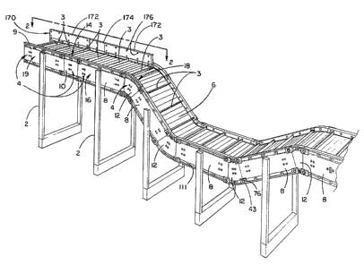
Referring to FIG. 1, an optional fence 170 can be
mounted to the framing means 4 to provide a retaining wall
for items being conveyed. The fence 170 prevents items from
falling off the conveyor and onto the floor. The fence 170
comprises a frame fence 172, a straight connector fence 174
and an angular connector fence (not shown). The frame fence
172 can be mounted to the straight frame 8. The straight
connector fence 174 can be mounted to the straight connector
frame 10. The angular connector fence can be mounted to the
angular connector frame 12.
An interior surface of the frame fence 172 has
five longitudinally spaced, vertically aligned pairs of
hexagonally shaped recesses 176 having bolt holes disposed
therein. These bolt holes extend through the frame fence
172 'to the exterior surface of the frame fence and are
axially aligned with bosses which project from the exterior
surface of the frame fence. The straight connector fence
174 and the angular connector fence each have one pair of
hexaganally shaped recesses 176. Also, the frame fence 172
has two tabs (not shown) which extend downwardly from the
frame fence 172. These tabs are constructed analogously to
the tabs 40 of the straight connector assembly 14 (FIG. 5).
Also analogous to the tabs 40, each of the tabs of the frame
fence has a bolt hole which extends through the tab and a
larger diameter recess in its innermost surface. The
straight connector fence 174 and the angular connector fence
each have one tab which extends downwardly.
Each of these fence assemblies may be mounted to
-18-
r~~~~~c~~"~
the respective portion of the conveyor frame in a similar
manner. For instance, the frame fence 172 may be mounted to
the straight frame 8 in the following manner. First, the
bottom of the frame fence 172 is placed against the top of
the projection 112 of the straight frame 8 so that it bears
against the projection 112. Next, two of the 'upper five
bosses 111 of the straight frame 8 are axially aligned with
the recesses of the downwardly extending tabs of the frame
fence. These two bosses 111 of the straight frame 8 are
then disposed within 'the axially aligned recesses of the
tabs of 'the frame fence. A nut and bolt (not shown) are
then used to secure each of these two tabs to 'the
corresponding bosses 111. Thus, the frame fence 172 is
connected to the straight frame 8.
Each part of the framing means 4 can be made of
synthetic plastic resin or cast from metal such as aluminum.
The preferred embodiment of the invention contemplates use
of the following materials for each part of the framing
means. The straight frame 8, the straight connector frame
10, the angular connector frame 12, the frame fence 172, the
straight connector fence 174, and the angular connector
fence are all preferably made of polycarbonate reinforced
with glass fibers. Also, each cross member 26 is preferably
made of polycarbonate reinforced with glass fibers.
Each belt guide 20, 132, 82, 142 and 144 should be
made from a wear resistant synthetic plastic resin having a
low coefficient of friction such as polybutylene
terephthalate. Also, each belt support 22, 100, 92 and 146
should be made of a wear resistant material having a low
coefficient of friction such as polybutylene terephthalate.
Each spacer rod 24 is preferably made of polyester resin
reinforced with fiberglass. Each sleeve 63 is preferably
made of an inexpensive material such as polyethylene or
rubber.
_19_
The above materials are thought to be the best
materials available for constructing the conveyor of the
present invention. Other materials having certain desired
characteristics can also be used. If different materials
are used, they should embody the prime characteristics of
the recommended materials such as strength, stiffness,
resistance to warpage, wear resistance, low coefficient of
friction, etc.
Each part of the frame assembly 16 and the
straight connector assembly 14 is symmetrical about a
central horizontal plane, symmetrical about a central
vertical transverse plane, arid symmetrical about a central
vertical longitudinal plane. Each part of the angular
connector assembly 18 is symmetrical about the central
vertical transverse plane and the central vertical
longitudinal plane.
The conveyor belt 6 is a link type belt having
links which are connected together with relatively stiff
rods. These rods are constructed the same as the spacer
rods 24 and are also preferably made of polyester resin
reinforced with fiberglass.
Because the conveyor belt 6 is relatively stiff
transversely but flexible longitudinally, the conveyor belt
can easily travel around the radii of the ends of the
conveyor and the angular connector assemblies l8. In
addition, the stiffness of the belt in the transverse
direction prevents the belt from coming out of the channels
88 of the angular connector bell. guides 82 and prevents
sagging of the belt on the bottom (return) of the conveyor
due to gravity.
The invention thus comprises a conveyor configura-
tion in which the framing means for supporting the conveyor
belt 6 consists of a plurality of synthetic plastic resin
modular units interconnected by means of the straight
-20-
connector assemblies 14 and the angular connector assemblies
18 to create a conveyor system having sections extending at
various angles to each other. The principal building block
for the modular conveyor is the frame assembly 16. each of
these units is interconnected by the straight connector
assembly 14 or the angular connector assembly 18 to
construct a conveyor system having any desired number of
straight or angular interconnections. The straight
connector assemblies 14 and the angular connector assemblies
18 are designed such that 'they can be used interchangeably
without affecting the length of the conveyor belt 6. Thus,
each time the angular connector assembly 18 is substituted
for the straight connector assembly 14 or vice versa, the
length of the conveyor belt need not be adjusted. This
aspect of the invention represents a major improvement over
the prior art conveyors. Secondly, the modularity of the
conveyor provides flexibility in constructing an unlimited
number of conveyor systems with ease. Furthermore, each
part of the framing means 4 can be made of a lightweight
2o plastic and can be formed in a uniform manner.
It is apparent that several of the hexagonally
shaped recesses 38, 74, 110, 176 having bolt holes disposed
therein are not utilized as described above. These
unutilized bolt holes are provided for the convenience of
the end user to use at his or heir discretion. The
unutilized bolt holes can be used to mount the support
members 2, suspend the conveyor from overhead, mount one
conveyor on top of another, or to mount auxiliary equipment.
Reasonable variation and modification are possible
within the spirit of the foregoing specification and
drawings without departing from the scope of the invention
which is defined in the accompanying claims.
-21-